EP1403107B1 - Klimaanlage mit einer elektronischen Überwachungsvorrichtung - Google Patents
Klimaanlage mit einer elektronischen Überwachungsvorrichtung Download PDFInfo
- Publication number
- EP1403107B1 EP1403107B1 EP03021442A EP03021442A EP1403107B1 EP 1403107 B1 EP1403107 B1 EP 1403107B1 EP 03021442 A EP03021442 A EP 03021442A EP 03021442 A EP03021442 A EP 03021442A EP 1403107 B1 EP1403107 B1 EP 1403107B1
- Authority
- EP
- European Patent Office
- Prior art keywords
- pressure
- value
- air conditioning
- compressor
- installation according
- Prior art date
- Legal status (The legal status is an assumption and is not a legal conclusion. Google has not performed a legal analysis and makes no representation as to the accuracy of the status listed.)
- Expired - Lifetime
Links
Images



Classifications
-
- B—PERFORMING OPERATIONS; TRANSPORTING
- B60—VEHICLES IN GENERAL
- B60H—ARRANGEMENTS OF HEATING, COOLING, VENTILATING OR OTHER AIR-TREATING DEVICES SPECIALLY ADAPTED FOR PASSENGER OR GOODS SPACES OF VEHICLES
- B60H1/00—Heating, cooling or ventilating devices
- B60H1/32—Cooling devices
- B60H1/3204—Cooling devices using compression
- B60H1/3205—Control means therefor
-
- B—PERFORMING OPERATIONS; TRANSPORTING
- B60—VEHICLES IN GENERAL
- B60H—ARRANGEMENTS OF HEATING, COOLING, VENTILATING OR OTHER AIR-TREATING DEVICES SPECIALLY ADAPTED FOR PASSENGER OR GOODS SPACES OF VEHICLES
- B60H1/00—Heating, cooling or ventilating devices
- B60H1/00642—Control systems or circuits; Control members or indication devices for heating, cooling or ventilating devices
- B60H1/00735—Control systems or circuits characterised by their input, i.e. by the detection, measurement or calculation of particular conditions, e.g. signal treatment, dynamic models
- B60H1/00792—Arrangement of detectors
-
- B—PERFORMING OPERATIONS; TRANSPORTING
- B60—VEHICLES IN GENERAL
- B60H—ARRANGEMENTS OF HEATING, COOLING, VENTILATING OR OTHER AIR-TREATING DEVICES SPECIALLY ADAPTED FOR PASSENGER OR GOODS SPACES OF VEHICLES
- B60H1/00—Heating, cooling or ventilating devices
- B60H1/00642—Control systems or circuits; Control members or indication devices for heating, cooling or ventilating devices
- B60H1/00814—Control systems or circuits characterised by their output, for controlling particular components of the heating, cooling or ventilating installation
- B60H1/00878—Control systems or circuits characterised by their output, for controlling particular components of the heating, cooling or ventilating installation the components being temperature regulating devices
- B60H1/00885—Controlling the flow of heating or cooling liquid, e.g. valves or pumps
-
- B—PERFORMING OPERATIONS; TRANSPORTING
- B60—VEHICLES IN GENERAL
- B60H—ARRANGEMENTS OF HEATING, COOLING, VENTILATING OR OTHER AIR-TREATING DEVICES SPECIALLY ADAPTED FOR PASSENGER OR GOODS SPACES OF VEHICLES
- B60H1/00—Heating, cooling or ventilating devices
- B60H1/32—Cooling devices
- B60H1/3204—Cooling devices using compression
- B60H1/3205—Control means therefor
- B60H1/3208—Vehicle drive related control of the compressor drive means, e.g. for fuel saving purposes
Definitions
- the invention relates to air conditioning circuits of motor vehicles.
- the air conditioning system compressor is driven by the engine and therefore consumes some of the power of the engine.
- the power absorbed by the compressor when it is running, is not important, however, it influences engine performance. Indeed, the power actually absorbed by the compressor decreases the efficiency of the engine, thus increasing the fuel consumption and pollution generated by vehicle exhaust.
- one solution is to estimate the power instantaneous actually absorbed by the compressor.
- Knowledge of this information allows, in fact, to adapt the engine injection parameters to real needs.
- the injection computer chooses, by default, parameters injection value corresponding to the maximum value of the power input, which is rarely achieved in practice.
- This disadvantage may concern the internal control mechanical compressors which operate through the clutch interposed between the engine and the compressor.
- the internal control compressors adapt their cubic capacity according to a linear law connecting the value of the pressure at the input of the compressor, so-called low pressure at the output value of the compressor, called high pressure. Yet, it happens that the power actually absorbed by the compressor is less than its power nominal.
- Such compressors absorb a power that depends on the operating conditions and that can not be reduced, even if we know the power actually absorbed by the compressor. On the other hand, it is possible to regulate the operation of the air conditioning by disengaging the compressor when the power is not acceptable.
- the estimate of the instantaneous power absorbed by the compressor is obtained from a map of the most USIT.
- This map includes reference states, each reference state being associated with a value of the power absorbed by the compressor, provided by tests prerequisites.
- the estimate of the power absorbed by the compressor is obtained by comparing the operating state of the air conditioning circuit to a reference state making part of the cartography.
- the instantaneous power absorbed by the compressor is calculated from an estimate of the refrigerant flow rate.
- the patent application French No. 01 16568 proposes an estimation of the flow of refrigerant in the circuit of air conditioning from information relating to the speed of the vehicle and a information relating to the voltage of the motor-fan unit. However, these two information is not available on all vehicles.
- the quantity relative to the fluid refrigerant is the mass flow of refrigerant while the electronic device of control is able to solve said equation from the value of the first pressure and the value of the second pressure.
- the quantity relative to the fluid refrigerant is the second pressure and the electronic control device is able to solve the equation from the value of the mass flow of the fluid and the value of the first pressure.
- the cooling member is a condenser and the installation includes measuring devices capable of providing a value relative to the temperature of the outside air flow at the condenser inlet and a value relative to the pressure of the fluid at the outlet of the compressor, said high pressure, while that the electronic control device is able to use the values provided by the measuring devices to implement the resolution of an equation, binding the flow mass of the refrigerant at the temperature of the outside air flow at the inlet of the condenser and at high pressure to calculate an estimate of the instantaneous value of the mass flow rate of the refrigerant.
- the compressor is at capacity variable and the magnitude relative to the refrigerant is the minimum value of the pressure of the fluid corresponding to the maximum displacement of the compressor, the electronic device control being able to solve said equation from the value of the first pressure and the value of the rotational speed of the compressor.
- the value of the rotational speed of the compressor can be supplied to the device electronic control by the injection computer.
- the installation comprises a compressor provided with a control valve and the second measuring device is a sensor clean to provide the value the intensity of the control valve, the electronic control device being able to calculate an initial estimate of the second pressure from the value of the intensity of the compressor control valve supplied by the second measured.
- the electronic control device is able to compare the initial estimate of the second pressure to the minimum value of the second pressure.
- the electronic control device is then able to react to the fact that the initial estimate the second pressure is less than or equal to the minimum value of the second pressure by providing a final estimate of the second substantially equal pressure at the minimum value of the second pressure.
- the electronic control device is also able to react to the fact that the second pressure is greater than the minimum value of the second pressure by providing a final estimate of the second pressure substantially equal to the initial estimate of the second pressure.
- the second member is a sensor placed at the level of second point, able to directly provide the instantaneous value of the second pressure.
- the first measuring member is a sensor placed at the level of the first point, able to provide the instantaneous value of the first pressure.
- the first measuring member may be a probe of temperature, placed in the fins of the evaporator, suitable for providing a measure of the instantaneous value of the air temperature in the evaporator.
- the first measuring device may be a temperature probe, placed downstream of the evaporator, capable of providing a measure of the instantaneous value the temperature of the air entering the evaporator.
- the first measuring device may be a probe of temperature to provide the instantaneous value of the fluid temperature, the probe being placed at the first point, in contact with the liquid part of the fluid.
- the first point is located at a location of the air conditioning circuit where the refrigerant is in a two-phase state.
- the detent may be a thermostatic expansion valve while the temperature sensor is placed in the zone fluid injection of the evaporator.
- the electronic control device is able to estimate the value the first pressure from the value provided by the temperature sensor.
- the temperature probe has a time constant less than or equal to 5 seconds.
- Appendix A contains the main mathematical equations used in the installation.
- FIG. 1a is an overview of an apparatus for air conditioning built into a vehicle.
- the air conditioning unit has a closed circuit of refrigerant.
- the air conditioning unit also comprises a compressor 14, a cooling member 11, an expansion member 12 and an evaporator 13, traveled in this order by the refrigerant.
- the circuit may also include an accumulator 17 between the evaporator outlet and the compressor inlet to prevent shots of liquid.
- the cooling member 11 receives an outside air flow 16 to evacuate the heat taken from the passenger compartment by the evaporator, which under certain operating conditions is set in motion by a motor-fan unit 15.
- the evaporator 13 receives a flow of air from a blower 20 fed by an outside air flow 18 and produces a flow of conditioned air 21 which is sent to the passenger compartment of the vehicle.
- the air conditioning circuit is traversed by a fluid subcritical refrigerant, for example R134a refrigerant.
- a fluid subcritical refrigerant for example R134a refrigerant.
- Such a fluid has a critical pressure greater than the pressure of the hot source.
- the organ of cooling 11 is a condenser.
- the detent member may for example be an orifice calibrated or a thermostatic expansion valve.
- the invention is not limited to air conditioning circuits operating with subcritical refrigerants and equipped with a cooling device of the type condenser.
- the air conditioning circuit may be traversed by a refrigerant supercritical, such as CO2 refrigerant.
- a refrigerant supercritical such as CO2 refrigerant.
- the high High temperature pressure is greater than the critical pressure of the fluid.
- Figure 1b represents an air conditioning circuit operating with the supercritical fluid CO2.
- the cooling member 11 is an external cooler ("gas cooler").
- the expansion member 12 may for example be an electric valve or a mechanical valve.
- the circuit comprises an evaporator 13, an accumulator 17 and a compressor 14 operating as described above.
- the circuit further comprises a heat exchanger internal 9.
- the cooling of the fluid after compression does not cause phase change.
- the fluid does not go to the state liquid only during the relaxation.
- the internal heat exchanger 9 makes it possible to cool very strongly, or even to liquefy the fluid leaving the external cooler 11.
- FIG. 2 is a diagram showing the installation according to the invention set up in a motor vehicle.
- the motor vehicle is driven by a motor 43, ordered by an injection computer 42.
- the computer receives information from various sensors that he interprets to adjust the parameters.
- the injection computer 42 is able to provide information on the conditions inside or outside the vehicle (information provided by a solar collector, number occupants, etc.). In particular, it provides information 33 on instantaneous values relating to the operation of the vehicle, and in particular the speed of rotation of the compressor N.
- the vehicle is also equipped with the air conditioning unit 10 described above, shown schematically in FIG. 2.
- the installation is provided with an air conditioning computer 40, comprising a cockpit regulator 41 and a regulator 402.
- the cabin controller 41 is intended to set the temperature setpoint T ac of the outside air blown at the inlet of the evaporator 11.
- the engine injection calculator 42 can act on the air conditioning unit thanks to the air conditioning loop controller 402 for controlling the start or stop of the air-conditioning unit under conditions related to the operation of the engine or external commands.
- the injection computer 42 may prohibit the implementation of operation of the air conditioning unit when the motor is under heavy load.
- the Applicant proposes to optimize the operation of the air conditioning circuit of a such an installation, by implementing an equation linking the flow of fluid in the circuit of air conditioning at a pressure difference between two points on the low line pressure.
- the low pressure line corresponds to the part of the circuit air conditioning which is located between the outlet of the regulator 12 and the inlet of the compressor 14.
- the cockpit regulator 41, the engine injection computer 42 and the air-conditioning unit 10 are connected to an electronic control device, for example example an electronic card 401 for an exchange of information.
- the electronic card 401 is programmed to solve the equations allowing to estimate the pressure difference on the low pressure line from measurements provided by installation and to solve the equation that links this pressure difference to the flow of Refrigerant.
- it may be programmed to implement the resolution an equation linking the power absorbed by the compressor to the flow of refrigerant to provide an estimate of the power absorbed by the compressor. She is arranged to transmit the information that results from these estimates to the injection computer 42, via the link 32.
- the electronic card 401 can be regarded as an integral part of the calculator of air conditioning 40 of the vehicle.
- cooling capacity the amount of heat taken from the passenger compartment
- the electronic card 401 can receive information from sensors placed on the air conditioning apparatus via the link 30. Such sensors are set up to determine the instantaneous value of the fluid pressure.
- the first pressure P 1 will be designated hereinafter by "origin pressure” and the second pressure P 2 by "suction pressure".
- the electronic card 401 is able to implement the connecting relationship the flow of refrigerant at the pressure difference between two points of the low line pressure to determine a magnitude relative to the refrigerant.
- this quantity relating to the fluid refrigerant is the flow of refrigerant. This value is particularly useful for estimate the power consumed by the air conditioning circuit and to adjust this consumption.
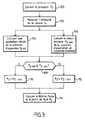
- FIG. 3 is a flowchart representing the steps implemented by the installation to provide this refrigerant flow rate estimate for a displacement compressor variable.
- step 100 the installation supplies the electronic card with the value of the origin pressure P 1 at point B1.
- the air conditioning circuit comprises a first measuring device able to provide a value relative to this origin pressure P 1 .
- the first member may be a temperature sensor that provides the instantaneous value of the air temperature T in the evaporator. This probe can be placed in the fins of the evaporator.
- the first member may be a temperature sensor 22 placed downstream of the evaporator which provides the instantaneous value of the air temperature T air at the inlet of the evaporator.
- the first member is a temperature sensor 122 implanted in the circuit at point B1 capable of supplying the temperature T FL of the refrigerant in the circuit.
- This probe 122 is placed in contact with the liquid part of the refrigerant.
- the origin point B 1 is advantageously placed in an area of the circuit where the fluid is in a two-phase state, which excludes the overheating zone from the evaporator.
- the part of the refrigerant in liquid form is important, which makes this area favorable to a such measure.
- the temperature sensor 122 (and thus the origin point B1) is placed in this fluid injection zone. Indeed, for air conditioning circuits using this type of regulator, the liquid phase of the fluid is quickly vaporized in the evaporator. The probe is placed at the beginning of the trip refrigerant in the evaporator so as to be in the most liquid phase possible.
- the probe used 122 (respectively 22) has a low constant time.
- the value of the temperature supplied by the probe 122 (respectively 22) is transmitted to the electronic card (link 30) which applies the fluid saturation law to deduce the value of the pressure of the fluid P 1 .
- the equation in Appendix A1.1 represents the law of saturation of the fluids connecting the pressure P 1 to the temperature T FL supplied by the probe 22.
- the equation of the appendix A1.2 represents the law of saturation of the fluids connecting the pressure P 1 to the temperature T air supplied by the probe 22.
- the electronic card further receives the value of the temperature of the air blown in downstream of the evaporator T ae , supplied by the cockpit regulator 41 and the efficiency value of the evaporator ⁇ ev to calculate the pressure P 1 .
- the efficiency value corresponds to a heat exchange efficiency. This value applies here only to the area of the evaporator where the probe is used.
- the electronic board receives the value measured by the probe 122 (respectively 22) by the link 30 and calculates the value of the origin pressure P 1 according to the equation of Appendix A1.1 (respectively A 1.2).
- the origin pressure P 1 can be measured directly by a sensor 222 placed at the point B1, for example at the inlet of the evaporator 13. This measurement is transmitted to the electronic card 401 via the link 30.
- the air conditioning circuit comprises a second measuring member able to provide a value relating to the suction pressure P 2 .
- the compressor of the air conditioning circuit is a variable displacement compressor provided with a control valve.
- the suction pressure P 2 of a variable displacement compressor is related to the intensity value Iv of the compressor control valve. Thus from the value of this intensity, it is possible to estimate the pressure P 2 at point B2.
- the second measuring device is able to determine the instantaneous value of the intensity I v of the compressor control valve and to transmit this value to the electronic card.
- the electronic card 401 estimates the value of the arrival pressure P 2 from the value of the intensity I v thus obtained.
- FIG. 4 represents an example of a curve connecting the suction pressure P 2 of a compressor to the intensity I v .
- This curve has been established for an externally controlled compressor.
- the equation corresponding to Part I of the curve is provided in Appendix A2.
- the suction pressure P 2 changes according to Iv (part I of the curve).
- the suction pressure of the compressor P 2 reaches the constant value P 2_min .
- the equation in Appendix A2 is no longer valid.
- the estimation of the suction pressure of the compressor P 2 from the measurement of the intensity Iv of the control valve can therefore be performed by determining whether the compressor is in maximum displacement, ie by determining whether the instantaneous value of the suction pressure of the fluid P 2 is less than or equal to P 2_min .
- the electronic card makes an initial estimate P 2_init of the suction pressure of the compressor from the intensity I v of the control valve and determines if the compressor is in maximum capacity. If necessary, the electronic card 401 adjusts the initial estimate of the suction pressure P 2_init of the compressor, which provides the final estimate P 2 of this pressure.
- the estimation of the suction pressure P 2 is carried out by the steps 102, 104, 106, 108, 110, and 112, according to this embodiment.
- step 102 the instantaneous value of the intensity I v of the control valve is measured by the second measuring member.
- This measuring device is a sensor that can be linked to any computer of the vehicle.
- step 104 the electronic card uses the equation linking the pressure P 2 to the intensity I v of the control valve, for example the equation in Appendix A2.1, to calculate an initial estimate of the suction pressure P 2_init of the compressor from the measured value of the intensity I v .
- the electronic card uses the equation of Annex A3 linking the flow rate of fluid in the air conditioning circuit at a pressure difference between points B1 and B2 to determine if the compressor is in maximum displacement.
- step 106 the electronic card calculates an estimate of the suction pressure when the compressor is in maximum capacity P 2_min from the equation of Appendix A3.
- the equation in Annex A3 provides the flow rate of refrigerant m as a function of the pressure origin P 1 and the suction pressure P 2 .
- the refrigerant flow rate m is related to the displacement of the compressor C y , to the high pressure P d , to the suction pressure P 2 and to the speed of rotation of the compressor N, according to the equation of the Annex A5.
- the identification of the equation of Annex A3 to the equation of Annex A5 provides the equation of Annex A6 which relates the suction pressure P 2 to the high pressure P d , to the pressure origin P 1 , at the speed of rotation of the compressor N and the cylinder capacity of the compressor C y .
- the value of the displacement C y of the compressor is known.
- the electronic card can thus calculate the suction pressure P 2_min of the fluid for a compressor in maximum capacity according to this equation.
- the value of the rotation speed N of the compressor is supplied to the card by the injection computer 42 via the link 33.
- the installation may comprise a pressure sensor 25 or a temperature sensor 125 to estimate the high pressure P d . In general, such sensors are present on the air conditioning circuits.
- the origin pressure P 1 was estimated at step 100.
- step 108 the electronic card compares the initial estimate P 2_init of the suction pressure of the compressor P 2 , obtained in step 104, with the value of the suction pressure of the compressor in maximum capacity P 2_min obtained in step 106 and provides in step 110 or 112 a final estimate of the suction pressure P 2 as a function of the result of the comparison.
- the value of the suction pressure P 2 corresponds to the initial estimate P 2_init of the suction pressure of the compressor obtained in step 104.
- the suction pressure P 2 is estimated according to the equation of the appendix.
- the electronic card can solve the equation of Annex A6 to provide the value of the suction pressure P 2 , the value of the speed of N rotation of the compressor provided by the injection computer 42, and the value of the high pressure P d provided by the sensor 25 (respectively 125).
- the second measuring member may be a pressure sensor 23, placed at the point B2, able to provide a measurement of the instantaneous value of the suction pressure P 2 of the compressor. This measurement is transmitted to the electronic card 401, via the link 30.
- step 114 the electronic card implements the equation of Appendix A3 and uses the estimated values of the origin pressure P 1 and the suction pressure P 2 to calculate a quantity relative to the refrigerant.
- the electronic card 401 solves the equation of Appendix A3 to calculate an estimate of the flow rate of refrigerant m in the air conditioning circuit.
- the pressure drop (P 1 -P 2 ) is calculated from the values of the pressures P 1 and P 2 estimated during the previous steps.
- S is a constant relative to the air conditioning circuit.
- the coefficient ⁇ corresponds to the charge density of the fluid used, for example that of the fluid R134a.
- the coefficient K is obtained as a function of the choice of calculation of the charge density ⁇ .
- This load density ⁇ can be calculated from the origin pressure P 1 , according to the equation in Appendix A4.1, or from the suction pressure P 2 , according to the equation in Appendix A4 .2, or from an average of these two pressures.
- Appendix A4.3 contains an example equation providing the charge density p for the subcritical R 134a refrigerant.
- the invention is not limited to an air conditioning circuit operating with a subcritical refrigerant.
- Appendix A4.4 is an example of an equation providing the charge density p for the super-critical CO2 refrigerant (R744).
- the estimation of the flow rate of refrigerant m is particularly useful in the air conditioning circuits. It allows in particular to calculate an estimate of the power absorbed by the compressor P a .
- the power P absorbed by the compressor may be estimated from the mass effect of refrigerant flow m obtained according to the first embodiment, for example according to the equation provided by the Annex A7.
- the electronic card 401 solves this equation from the value of the flow rate of refrigerant m estimated according to the invention, the value of the speed of rotation of the compressor N supplied by the injection computer 42, the value of the pressure suction P 2 previously estimated and the value of the high pressure P d provided by the sensor 25 (respectively 125).
- the constants C and D are related to operating parameters of the air conditioning circuit and therefore fixed as calculation parameters.
- the computer then sends the engine injection module the estimated value of the mechanical power absorbed by the compressor P a and adapts the nominal power absorbed by the compressor, if it exceeds a maximum value defined by the computer from this point of view. estimated value. As a result, the fuel consumption is reduced and the excessive increases in the power absorbed by the compressor are better controlled.
- Figure 4 illustrates the accuracy of the estimation of the refrigerant flow rate m according to this embodiment for the subcritical refrigerant R134a.
- the figure is a diagram representing the value of the flow of refrigerant m (ordinates) as a function of the value of the difference of [ ⁇ * (P 1 - P 2 )] (abscissa).
- the origin point B1 is located at the outlet of the evaporator.
- the square-shaped points are obtained for a measured suction pressure P 2 and an origin pressure P 1 estimated from the air temperature measurement probe.
- the diamond-shaped points are obtained for a pressure P 1 and a pressure P 2 measured.
- the installation according to the invention is used to obtain an estimate of the suction pressure P 2 of the refrigerant.
- the electronic card 401 implements the resolution of the equation of Appendix A3 to calculate an estimate of the suction pressure P 2 of the refrigerant, when the vehicle is already equipped with a known device for estimating the flow of refrigerant.
- a known device for estimating the flow of refrigerant is described in French Patent Application No. 01 16568.
- the cooling member is a condenser, which allows the use of a subcritical refrigerant, such as the refrigerant R134.
- This device comprises measuring devices for establishing values relating to the temperature of the outside air flow at the inlet of the condenser T aek and the pressure P d of the refrigerant at the outlet of the compressor.
- the electronic card then implements the equation of Appendix A1 to calculate an estimate of the flow rate of refrigerant m in the air conditioning circuit from the values of the temperature of the outside air flow blown at the inlet of the condenser T ack , and the pressure of the refrigerant at the outlet of the compressor P d .
- the value of the origin pressure P 1 is provided by step 100.
- the charge density of the fluid ⁇ can be estimated from P 1 according to Appendix A4.1.
- the device of patent JP 2001-73941 can operate with an air conditioning circuit in which the cooling member is an external cooler ("gas cooler") and the fluid Refrigerant is the supercritical fluid CO2 (R744).
- the cooling member is an external cooler ("gas cooler")
- the fluid Refrigerant is the supercritical fluid CO2 (R744).
- This estimate P 2 can be used to calculate the power consumed by the compressor and also ensure its proper operation. It can also be used to control or validate a value of the suction pressure obtained by other means, such as that obtained for example by using the intensity of the current of the compressor valve according to steps 102 and 104.
- the electronic card 401 solves the equation in Annex A3 to detect the maximum displacement of a compressor at variable displacement.
- the first embodiment of the invention uses this detection the maximum displacement, but the detection of the displacement of the compressor may be used in other applications. For example, in the context of a regulation / control of the cold loop, this detection is used to stop the control of the compressor and thus optimize the regulation of the supply air temperature.
- This form of embodiment has been described with reference to steps 102, 104, 106, 108, 110 and 112 of FIG. 3.
- the present invention also aims at the software code that it involves, while especially when it is made available on any support readable on a computer.
- computer-readable medium covers a storage medium, for example magnetic or optical, as well as a transmission means, such as a signal digital or analog.
Landscapes
- Physics & Mathematics (AREA)
- Thermal Sciences (AREA)
- Engineering & Computer Science (AREA)
- Mechanical Engineering (AREA)
- Air-Conditioning For Vehicles (AREA)
- Air Conditioning Control Device (AREA)
Claims (19)
- Klimatisierungsanlage für Kraftfahrzeuge, die mit einem Einspritzrechner (42) und einem Kältemittelkreis versehen ist, der einen Kompressor (14), ein Kühlglied (11), ein Entspannungsglied (12) und einen Verdampfer (13) enthält, sowie mit einer elektronischen Steuervorrichtung (401), die dazu bestimmt ist, mit dem Kältemittelkreis (10) und dem Einspritzrechner (42) in Wechselwirkung zu treten,
dadurch gekennzeichnet, dass sie enthält:und dass die elektronische Steuervorrichtung (401) die Lösung einer Gleichung umsetzen kann, welche den Massendurchsatz (m) des Kältemittels mit der Druckdifferenz zwischen erstem Punkt und zweitem Punkt (P1-P2) in Beziehung setzt, um einen Schätzwert für eine auf das Kältemittel bezogene Größe zu errechnen.ein erstes Messglied, das an einem ersten Punkt des Klimatisierungskreises (B1) einen auf den Druck des Kältemittels bezogenen Wert, erster Druck (P1) genannt, liefern kann, wobei der genannte erste Punkt zwischen dem Auslass des Entspannungsglieds und dem Auslass des Verdampfers liegt,ein zweites Messglied, das an einem zweiten Punkt des Klimatisierungskreises (B2) einen auf den Druck des Kältemittels bezogenen Wert, zweiter Druck (P2) genannt, liefern kann, wobei der genannte zweite Punkt am Einlass des Kompressors liegt, - Klimatisierungsanlage nach Anspruch 1, dadurch gekennzeichnet, dass die auf das Kältemittel bezogene Größe der Massendurchsatz (m) des Kältemittels ist und dass die elektronische Steuervorrichtung (401) die genannte Gleichung aus dem Wert des ersten Drucks (P1) und dem Wert des zweiten Drucks (P2) lösen kann.
- Klimatisierungsanlage nach Anspruch 1, dadurch gekennzeichnet, dass die auf das Kältemittel bezogene Größe der zweite Druck (P2) ist und dass die elektronische Steuervorrichtung (401) die genannte Gleichung aus dem Wert des ersten Drucks (P1) und dem Wert des zweiten Drucks (P2) lösen kann
- Klimatisierungsanlage nach Anspruch 3, dadurch gekennzeichnet, dass das Kühlglied ein Kondensator ist und dass sie Messglieder enthält, welche einen auf die Temperatur der Außenluftströmung am Einlass des Kondensators (Taek) bezogenen Wert und einen auf den Druck des Kältemittels am Auslass des Kompressors bezogenen Wert, Hochdruck (Pd) genannt, liefern können, wobei die elektronische Steuervorrichtung (401) die von den genannten Messgliedern gelieferten Werte verwenden kann, um die Lösung einer Gleichung umzusetzen, welche den Massendurchsatz (m) des Kältemittels mit der Temperatur der Außenluftströmung am Einlass des Kondensators (Taek) und mit dem Hochdruck (Pd) in Beziehung setzt, um einen Schätzwert für den momentanen Wert des Massendurchsatzes (m) des Kältemittels zu errechnen.
- Klimatisierungsanlage nach Anspruch 1, dadurch gekennzeichnet, dass der Kompressor im Fördervolumen verstellbar ist und dass die auf das Kältemittel bezogene Größe der Mindestwert des Kältemitteldrucks (P2_min) ist, der dem maximalen Fördervolumen des Kompressors entspricht, wobei die elektronische Steuervorrichtung die genannte Gleichung aus dem Wert des ersten Drucks (P1) und dem Wert der Drehzahl (N) des Kompressors lösen kann.
- Klimatisierungsanlage nach Anspruch 3, dadurch gekennzeichnet, dass der Wert der Drehzahl (N) des Kompressors über den Einspritzrechner der elektronischen Steuervorrichtung zugeführt wird.
- Klimatisierungsanlage nach einem der vorangehenden Ansprüche, dadurch gekennzeichnet, dass der Kompressor mit einem Steuerventil versehen ist und dass das zweite Messglied ein Sensor ist, der den momentanen Wert der Leistung des Steuerventils (Iv) liefern kann, wobei die elektronische Steuervorrichtung (401) einen anfänglichen Schätzwert des zweiten Drucks (P2-init) aus dem Wert der Leistung (Iv) des Steuerventils des Kompressors errechnen kann, der vom zweiten Messglied geliefert wird.
- Klimatisierungsanlage nach Anspruch 7 in Kombination mit Anspruch 5, dadurch gekennzeichnet, dass die elektronische Steuervorrichtung (401) den anfänglichen Schätzwert des zweiten Drucks (P2-init) mit dem Mindestwert des zweiten Drucks (P2_min) vergleichen kann.
- Klimatisierungsanlage nach Anspruch 8, dadurch gekennzeichnet, dass die elektronische Steuervorrichtung (401) darauf reagieren kann, dass der anfängliche Schätzwert des zweiten Drucks (P2_init) kleiner oder gleich dem Mindestwert des zweiten Drucks (P2_min) ist, indem sie einen endgültigen Schätzwert des zweiten Drucks (P2) liefert, der im wesentlichen gleich dem Mindestwert des zweiten Drucks (P2_min) ist.
- Klimatisierungsanlage nach Anspruch 8, dadurch gekennzeichnet, dass die elektronische Steuervorrichtung (401) darauf reagieren kann, dass der zweite Druck (P2_init) größer als der Mindestwert des zweiten Drucks (P2_min) ist, indem sie einen endgültigen Schätzwert des zweiten Drucks (P2) liefert, der im wesentlichen gleich dem anfänglichen Schätzwert des zweiten Drucks (P2_min) ist.
- Klimatisierungsanlage nach einem der Ansprüche 1 bis 4, dadurch gekennzeichnet, dass das zweite Glied ein Sensor (23) ist, der im Bereich des zweiten Punkts angeordnet ist und den momentanen Wert des zweiten Drucks (P2) liefern kann.
- Klimatisierungsanlage nach einem der vorangehenden Ansprüche, dadurch gekennzeichnet, dass das erste Messglied ein Sensor (222) ist, der im Bereich des ersten Punkts angeordnet ist und direkt den momentanen Wert des ersten Drucks (P1) liefern kann.
- Klimatisierungsanlage nach einem der Ansprüche 1 bis 11, dadurch gekennzeichnet, dass das erste Messglied ein Temperaturfühler (22) ist, der in den Rippen des Verdampfers (13) angeordnet ist und eine Messung des momentanen Werts der Temperatur (Tair) der Luft im Verdampfer liefern kann.
- Klimatisierungsanlage nach einem der Ansprüche 1 bis 11, dadurch gekennzeichnet, dass das erste Messglied ein Temperaturfühler (22) ist, der dem Verdampfer (13) vorgelagert ist und eine Messung des momentanen Werts der Temperatur (Tair) der in den Verdampfer einströmenden Luft liefern kann.
- Klimatisierungsanlage nach einem der Ansprüche 1 bis 11, dadurch gekennzeichnet, dass das erste Messglied ein Temperaturfühler (122) ist, der den momentanen Wert der Temperatur (TFL) des Kältemittels liefern kann, wobei der Fühler im Bereich des ersten Punkts mit dem Flüssigteil des Druckmittels in Kontakt stehend angeordnet ist.
- Klimatisierungsanlage nach Anspruch 15, dadurch gekennzeichnet, dass der erste Punkt (B 1) sich an einer Stelle des Klimatisierungskreises befindet, an der das Kältemittel in einem Zweiphasenzustand ist.
- Klimatisierungsanlage nach einem der Ansprüche 13 und 15, bei der das Entspannungsglied ein thermostatischer Druckminderer ist, dadurch gekennzeichnet, dass der Temperaturfühler (122) im Kältemitteleinspritzbereich des Verdampfers angeordnet ist.
- Klimatisierungsanlage nach einem der Ansprüche 13 bis 17, dadurch gekennzeichnet, dass die elektronische Steuervorrichtung den Wert des ersten Drucks (P1) aus dem von dem Temperaturfühler (122, 22) gelieferten Wert schätzen kann.
- Klimatisierungsanlage nach einem der Ansprüche 13 bis 18, dadurch gekennzeichnet, dass der Temperaturfühler (22, 122) eine Zeitkonstante kleiner oder gleich 5 Sekunden hat.
Applications Claiming Priority (2)
| Application Number | Priority Date | Filing Date | Title |
|---|---|---|---|
| FR0211988A FR2845035B1 (fr) | 2002-09-27 | 2002-09-27 | Installation de climatisation comprenant un dispositif electronique de controle |
| FR0211988 | 2002-09-27 |
Publications (2)
| Publication Number | Publication Date |
|---|---|
| EP1403107A1 EP1403107A1 (de) | 2004-03-31 |
| EP1403107B1 true EP1403107B1 (de) | 2005-01-26 |
Family
ID=31971015
Family Applications (1)
| Application Number | Title | Priority Date | Filing Date |
|---|---|---|---|
| EP03021442A Expired - Lifetime EP1403107B1 (de) | 2002-09-27 | 2003-09-23 | Klimaanlage mit einer elektronischen Überwachungsvorrichtung |
Country Status (7)
| Country | Link |
|---|---|
| US (1) | US6796137B2 (de) |
| EP (1) | EP1403107B1 (de) |
| JP (1) | JP2004115012A (de) |
| AT (1) | ATE287803T1 (de) |
| DE (1) | DE60300295T2 (de) |
| ES (1) | ES2237731T3 (de) |
| FR (1) | FR2845035B1 (de) |
Families Citing this family (9)
| Publication number | Priority date | Publication date | Assignee | Title |
|---|---|---|---|---|
| JP3861797B2 (ja) * | 2002-10-31 | 2006-12-20 | 株式会社デンソー | 車両用空調装置 |
| FR2862573B1 (fr) * | 2003-11-25 | 2006-01-13 | Valeo Climatisation | Installation de climatisation de vehicule |
| EP1880149A4 (de) * | 2005-04-05 | 2012-09-26 | Product Group Llc | Intelligente steuerung für kühl- und klimaanlagen |
| JP4114691B2 (ja) * | 2005-12-16 | 2008-07-09 | ダイキン工業株式会社 | 空気調和装置 |
| FR2913102B1 (fr) * | 2007-02-28 | 2012-11-16 | Valeo Systemes Thermiques | Installation de climatisation equipee d'une vanne de detente electrique |
| JP5765566B2 (ja) * | 2010-07-23 | 2015-08-19 | サンデンホールディングス株式会社 | 車両用空調装置及び車両用空調装置における可変容量圧縮機の運転状態判定方法 |
| DE102011053894A1 (de) * | 2010-11-23 | 2012-05-24 | Visteon Global Technologies, Inc. | Kälteanlage mit Kältemittelverdampferanordnung und Verfahren zur parallelen Luft- und Batteriekontaktkühlung |
| US10358015B2 (en) * | 2016-03-15 | 2019-07-23 | Caterpillar Inc. | Air-conditioning system for a machine |
| DE102023121734A1 (de) | 2023-08-14 | 2025-02-20 | Konvekta Aktiengesellschaft | Verbesserte Kompressionskältemaschine und Verfahren zum Regeln und/oder Überwachen dessen Kältemittelkreislaufs |
Family Cites Families (13)
| Publication number | Priority date | Publication date | Assignee | Title |
|---|---|---|---|---|
| US4510576A (en) * | 1982-07-26 | 1985-04-09 | Honeywell Inc. | Specific coefficient of performance measuring device |
| CA1247385A (en) * | 1984-07-02 | 1988-12-28 | Kosaku Sayo | Apparatus for measuring refrigerant flow rate in refrigeration cycle |
| JPH0538937A (ja) * | 1991-08-01 | 1993-02-19 | Toyota Autom Loom Works Ltd | 空調装置 |
| FR2711731B1 (fr) * | 1993-10-26 | 1995-12-01 | Valeo Thermique Habitacle | Dispositif de détection relatif à la climatisation d'un véhicule à moteur muni d'un calculateur d'injection. |
| JP3858297B2 (ja) * | 1996-01-25 | 2006-12-13 | 株式会社デンソー | 圧力制御弁と蒸気圧縮式冷凍サイクル |
| JP3329275B2 (ja) * | 1997-10-07 | 2002-09-30 | 株式会社デンソー | 車両用空調装置 |
| DE19935731A1 (de) * | 1999-07-29 | 2001-02-15 | Daimler Chrysler Ag | Verfahren zum Betreiben einer unter- und transkritisch betriebenen Fahrzeugkälteanlage |
| JP3941303B2 (ja) * | 1999-11-17 | 2007-07-04 | 株式会社豊田自動織機 | 空調装置 |
| JP3855571B2 (ja) * | 1999-12-24 | 2006-12-13 | 株式会社豊田自動織機 | 内燃機関の出力制御方法 |
| JP4221893B2 (ja) * | 2000-02-28 | 2009-02-12 | 株式会社豊田自動織機 | 容量可変型圧縮機の容量制御装置及び圧縮機モジュール |
| JP4096491B2 (ja) * | 2000-03-15 | 2008-06-04 | 株式会社デンソー | 冷凍サイクル装置 |
| US6701725B2 (en) * | 2001-05-11 | 2004-03-09 | Field Diagnostic Services, Inc. | Estimating operating parameters of vapor compression cycle equipment |
| JP2004034943A (ja) * | 2002-07-08 | 2004-02-05 | Tgk Co Ltd | 冷凍サイクルの制御方法 |
-
2002
- 2002-09-27 FR FR0211988A patent/FR2845035B1/fr not_active Expired - Fee Related
-
2003
- 2003-09-22 US US10/667,924 patent/US6796137B2/en not_active Expired - Fee Related
- 2003-09-23 AT AT03021442T patent/ATE287803T1/de not_active IP Right Cessation
- 2003-09-23 DE DE60300295T patent/DE60300295T2/de not_active Expired - Lifetime
- 2003-09-23 ES ES03021442T patent/ES2237731T3/es not_active Expired - Lifetime
- 2003-09-23 EP EP03021442A patent/EP1403107B1/de not_active Expired - Lifetime
- 2003-09-26 JP JP2003334971A patent/JP2004115012A/ja active Pending
Also Published As
| Publication number | Publication date |
|---|---|
| FR2845035A1 (fr) | 2004-04-02 |
| DE60300295D1 (de) | 2005-03-03 |
| ES2237731T3 (es) | 2005-08-01 |
| FR2845035B1 (fr) | 2004-12-24 |
| US6796137B2 (en) | 2004-09-28 |
| DE60300295T2 (de) | 2005-12-22 |
| EP1403107A1 (de) | 2004-03-31 |
| JP2004115012A (ja) | 2004-04-15 |
| US20040060310A1 (en) | 2004-04-01 |
| ATE287803T1 (de) | 2005-02-15 |
Similar Documents
| Publication | Publication Date | Title |
|---|---|---|
| EP1965156B1 (de) | Klimaanlage mit elektrischem Entspannungsventil | |
| EP1456045B1 (de) | Mit einer elektronischen steuervorrichtung ausgestattete kraftfahrzeug-klimaanlage | |
| FR2954405A1 (fr) | Dispositif de refroidissement pour vehicule automobile | |
| EP1403107B1 (de) | Klimaanlage mit einer elektronischen Überwachungsvorrichtung | |
| EP1325269B1 (de) | Fahrzeugklimaanlage unter verwendung eines überkritischen kreislaufes | |
| EP1509417B1 (de) | Fahrzeugklimaanlageneinheit mit elektronischer steuervorrichtung | |
| EP1687161B1 (de) | Fahrzeugklimaanlagenanordnung | |
| EP2651674B1 (de) | System und verfahren zur steuerung eines klimaanlagensystems für ein kraftfahrzeug | |
| EP2699434B1 (de) | Verfahren zur regelung einer klimaanlage in einer fahrgastzelle eines fahrzeuges | |
| WO2004028841A1 (fr) | Installation de climatisation munie d’un dispositif de detection et d’estimation de l’humidite de l’air | |
| EP1493979A1 (de) | Fahrzeugklimaanlage mit überkritischem Kreislauf | |
| EP1459920B1 (de) | Klimaanlage eines Fahrzeugs für ein überkritisches Kühlmittel | |
| EP4479692B1 (de) | Kühlvorrichtung und -verfahren | |
| WO2004005059A1 (fr) | Installation de climatisation munie d’un dispositif electronique de controle | |
| FR2912084A1 (fr) | Installation de climatisation munie d'un dispositif de controle de givrage | |
| FR3115733A1 (fr) | Procédé de régulation d’un détendeur électronique d’un système de climatisation et système de climatisation associé | |
| FR3078923A1 (fr) | Procede et systeme de commande d'un systeme de regulation thermique d'un vehicule automobile | |
| EP0911622B1 (de) | Verfahren und Gerät zur Bestimmung der von einem Motor an einer Klimaanlage abgegebenen Leistung und deren Anwendungen | |
| FR3040333B1 (fr) | Circuit de gestion thermique d'un vehicule automobile comprenant une boucle de rankine et procede de pilotage associe | |
| WO2026002631A1 (fr) | Système de conditionnement thermique | |
| FR3091562A1 (fr) | Procédé de contrôle d’un compresseur de climatisation électrique et système de climatisation mettant en œuvre un tel procédé de contrôle | |
| FR3166330A1 (fr) | Système de conditionnement d’air pour véhicule et procédé de contrôle associé | |
| WO2014095592A1 (fr) | Systeme de regulation d'une detente d'un fluide refrigerant | |
| FR2999691A1 (fr) | Systeme de regulation electrique d'une detente d'un fluide refrigerant et procede de commande d'un tel systeme |
Legal Events
| Date | Code | Title | Description |
|---|---|---|---|
| PUAI | Public reference made under article 153(3) epc to a published international application that has entered the european phase |
Free format text: ORIGINAL CODE: 0009012 |
|
| AK | Designated contracting states |
Kind code of ref document: A1 Designated state(s): AT BE BG CH CY CZ DE DK EE ES FI FR GB GR HU IE IT LI LU MC NL PT RO SE SI SK TR |
|
| AX | Request for extension of the european patent |
Extension state: AL LT LV MK |
|
| 17P | Request for examination filed |
Effective date: 20040518 |
|
| GRAP | Despatch of communication of intention to grant a patent |
Free format text: ORIGINAL CODE: EPIDOSNIGR1 |
|
| GRAS | Grant fee paid |
Free format text: ORIGINAL CODE: EPIDOSNIGR3 |
|
| GRAA | (expected) grant |
Free format text: ORIGINAL CODE: 0009210 |
|
| AKX | Designation fees paid |
Designated state(s): AT BE BG CH CY CZ DE DK EE ES FI FR GB GR HU IE IT LI LU MC NL PT RO SE SI SK TR |
|
| AK | Designated contracting states |
Kind code of ref document: B1 Designated state(s): AT BE BG CH CY CZ DE DK EE ES FI FR GB GR HU IE IT LI LU MC NL PT RO SE SI SK TR |
|
| PG25 | Lapsed in a contracting state [announced via postgrant information from national office to epo] |
Ref country code: FI Free format text: LAPSE BECAUSE OF FAILURE TO SUBMIT A TRANSLATION OF THE DESCRIPTION OR TO PAY THE FEE WITHIN THE PRESCRIBED TIME-LIMIT Effective date: 20050126 Ref country code: RO Free format text: LAPSE BECAUSE OF FAILURE TO SUBMIT A TRANSLATION OF THE DESCRIPTION OR TO PAY THE FEE WITHIN THE PRESCRIBED TIME-LIMIT Effective date: 20050126 Ref country code: IE Free format text: LAPSE BECAUSE OF FAILURE TO SUBMIT A TRANSLATION OF THE DESCRIPTION OR TO PAY THE FEE WITHIN THE PRESCRIBED TIME-LIMIT Effective date: 20050126 Ref country code: EE Free format text: LAPSE BECAUSE OF FAILURE TO SUBMIT A TRANSLATION OF THE DESCRIPTION OR TO PAY THE FEE WITHIN THE PRESCRIBED TIME-LIMIT Effective date: 20050126 Ref country code: NL Free format text: LAPSE BECAUSE OF FAILURE TO SUBMIT A TRANSLATION OF THE DESCRIPTION OR TO PAY THE FEE WITHIN THE PRESCRIBED TIME-LIMIT Effective date: 20050126 Ref country code: AT Free format text: LAPSE BECAUSE OF FAILURE TO SUBMIT A TRANSLATION OF THE DESCRIPTION OR TO PAY THE FEE WITHIN THE PRESCRIBED TIME-LIMIT Effective date: 20050126 Ref country code: TR Free format text: LAPSE BECAUSE OF FAILURE TO SUBMIT A TRANSLATION OF THE DESCRIPTION OR TO PAY THE FEE WITHIN THE PRESCRIBED TIME-LIMIT Effective date: 20050126 Ref country code: BG Free format text: LAPSE BECAUSE OF FAILURE TO SUBMIT A TRANSLATION OF THE DESCRIPTION OR TO PAY THE FEE WITHIN THE PRESCRIBED TIME-LIMIT Effective date: 20050126 Ref country code: SI Free format text: LAPSE BECAUSE OF FAILURE TO SUBMIT A TRANSLATION OF THE DESCRIPTION OR TO PAY THE FEE WITHIN THE PRESCRIBED TIME-LIMIT Effective date: 20050126 Ref country code: SK Free format text: LAPSE BECAUSE OF FAILURE TO SUBMIT A TRANSLATION OF THE DESCRIPTION OR TO PAY THE FEE WITHIN THE PRESCRIBED TIME-LIMIT Effective date: 20050126 |
|
| REG | Reference to a national code |
Ref country code: GB Ref legal event code: FG4D Free format text: NOT ENGLISH |
|
| REG | Reference to a national code |
Ref country code: CH Ref legal event code: EP |
|
| REG | Reference to a national code |
Ref country code: IE Ref legal event code: FG4D Free format text: FRENCH |
|
| REF | Corresponds to: |
Ref document number: 60300295 Country of ref document: DE Date of ref document: 20050303 Kind code of ref document: P |
|
| RAP2 | Party data changed (patent owner data changed or rights of a patent transferred) |
Owner name: VALEO SYSTEMES THERMIQUES SAS |
|
| PG25 | Lapsed in a contracting state [announced via postgrant information from national office to epo] |
Ref country code: DK Free format text: LAPSE BECAUSE OF FAILURE TO SUBMIT A TRANSLATION OF THE DESCRIPTION OR TO PAY THE FEE WITHIN THE PRESCRIBED TIME-LIMIT Effective date: 20050426 Ref country code: GR Free format text: LAPSE BECAUSE OF FAILURE TO SUBMIT A TRANSLATION OF THE DESCRIPTION OR TO PAY THE FEE WITHIN THE PRESCRIBED TIME-LIMIT Effective date: 20050426 |
|
| PG25 | Lapsed in a contracting state [announced via postgrant information from national office to epo] |
Ref country code: HU Free format text: LAPSE BECAUSE OF FAILURE TO SUBMIT A TRANSLATION OF THE DESCRIPTION OR TO PAY THE FEE WITHIN THE PRESCRIBED TIME-LIMIT Effective date: 20050427 |
|
| GBT | Gb: translation of ep patent filed (gb section 77(6)(a)/1977) |
Effective date: 20050411 |
|
| REG | Reference to a national code |
Ref country code: SE Ref legal event code: TRGR |
|
| NLT2 | Nl: modifications (of names), taken from the european patent patent bulletin |
Owner name: VALEO SYSTEMES THERMIQUES SAS |
|
| NLV1 | Nl: lapsed or annulled due to failure to fulfill the requirements of art. 29p and 29m of the patents act | ||
| REG | Reference to a national code |
Ref country code: ES Ref legal event code: FG2A Ref document number: 2237731 Country of ref document: ES Kind code of ref document: T3 |
|
| REG | Reference to a national code |
Ref country code: IE Ref legal event code: FD4D |
|
| PG25 | Lapsed in a contracting state [announced via postgrant information from national office to epo] |
Ref country code: CY Free format text: LAPSE BECAUSE OF FAILURE TO SUBMIT A TRANSLATION OF THE DESCRIPTION OR TO PAY THE FEE WITHIN THE PRESCRIBED TIME-LIMIT Effective date: 20050923 |
|
| PG25 | Lapsed in a contracting state [announced via postgrant information from national office to epo] |
Ref country code: MC Free format text: LAPSE BECAUSE OF NON-PAYMENT OF DUE FEES Effective date: 20050930 Ref country code: BE Free format text: LAPSE BECAUSE OF NON-PAYMENT OF DUE FEES Effective date: 20050930 Ref country code: LU Free format text: LAPSE BECAUSE OF NON-PAYMENT OF DUE FEES Effective date: 20050930 |
|
| PLBE | No opposition filed within time limit |
Free format text: ORIGINAL CODE: 0009261 |
|
| STAA | Information on the status of an ep patent application or granted ep patent |
Free format text: STATUS: NO OPPOSITION FILED WITHIN TIME LIMIT |
|
| 26N | No opposition filed |
Effective date: 20051027 |
|
| PG25 | Lapsed in a contracting state [announced via postgrant information from national office to epo] |
Ref country code: FR Free format text: LAPSE BECAUSE OF NON-PAYMENT OF DUE FEES Effective date: 20060531 |
|
| REG | Reference to a national code |
Ref country code: FR Ref legal event code: ST Effective date: 20060531 |
|
| BERE | Be: lapsed |
Owner name: VALEO CLIMATISATION Effective date: 20050930 |
|
| PG25 | Lapsed in a contracting state [announced via postgrant information from national office to epo] |
Ref country code: PT Free format text: LAPSE BECAUSE OF NON-PAYMENT OF DUE FEES Effective date: 20050626 |
|
| REG | Reference to a national code |
Ref country code: CH Ref legal event code: PL |
|
| PG25 | Lapsed in a contracting state [announced via postgrant information from national office to epo] |
Ref country code: CH Free format text: LAPSE BECAUSE OF NON-PAYMENT OF DUE FEES Effective date: 20070930 Ref country code: LI Free format text: LAPSE BECAUSE OF NON-PAYMENT OF DUE FEES Effective date: 20070930 |
|
| PGFP | Annual fee paid to national office [announced via postgrant information from national office to epo] |
Ref country code: CZ Payment date: 20130820 Year of fee payment: 11 Ref country code: ES Payment date: 20130920 Year of fee payment: 11 Ref country code: SE Payment date: 20130912 Year of fee payment: 11 |
|
| PGFP | Annual fee paid to national office [announced via postgrant information from national office to epo] |
Ref country code: GB Payment date: 20130920 Year of fee payment: 11 |
|
| PGFP | Annual fee paid to national office [announced via postgrant information from national office to epo] |
Ref country code: IT Payment date: 20130920 Year of fee payment: 11 |
|
| PG25 | Lapsed in a contracting state [announced via postgrant information from national office to epo] |
Ref country code: CZ Free format text: LAPSE BECAUSE OF NON-PAYMENT OF DUE FEES Effective date: 20140923 |
|
| REG | Reference to a national code |
Ref country code: SE Ref legal event code: EUG |
|
| GBPC | Gb: european patent ceased through non-payment of renewal fee |
Effective date: 20140923 |
|
| PG25 | Lapsed in a contracting state [announced via postgrant information from national office to epo] |
Ref country code: SE Free format text: LAPSE BECAUSE OF NON-PAYMENT OF DUE FEES Effective date: 20140924 |
|
| PG25 | Lapsed in a contracting state [announced via postgrant information from national office to epo] |
Ref country code: GB Free format text: LAPSE BECAUSE OF NON-PAYMENT OF DUE FEES Effective date: 20140923 |
|
| PG25 | Lapsed in a contracting state [announced via postgrant information from national office to epo] |
Ref country code: IT Free format text: LAPSE BECAUSE OF NON-PAYMENT OF DUE FEES Effective date: 20140923 |
|
| REG | Reference to a national code |
Ref country code: ES Ref legal event code: FD2A Effective date: 20151027 |
|
| PG25 | Lapsed in a contracting state [announced via postgrant information from national office to epo] |
Ref country code: ES Free format text: LAPSE BECAUSE OF NON-PAYMENT OF DUE FEES Effective date: 20140924 |
|
| PGFP | Annual fee paid to national office [announced via postgrant information from national office to epo] |
Ref country code: DE Payment date: 20160914 Year of fee payment: 14 |
|
| REG | Reference to a national code |
Ref country code: DE Ref legal event code: R119 Ref document number: 60300295 Country of ref document: DE |
|
| PG25 | Lapsed in a contracting state [announced via postgrant information from national office to epo] |
Ref country code: DE Free format text: LAPSE BECAUSE OF NON-PAYMENT OF DUE FEES Effective date: 20180404 |