EP1403130A2 - Véhicule de travail - Google Patents
Véhicule de travail Download PDFInfo
- Publication number
- EP1403130A2 EP1403130A2 EP03019247A EP03019247A EP1403130A2 EP 1403130 A2 EP1403130 A2 EP 1403130A2 EP 03019247 A EP03019247 A EP 03019247A EP 03019247 A EP03019247 A EP 03019247A EP 1403130 A2 EP1403130 A2 EP 1403130A2
- Authority
- EP
- European Patent Office
- Prior art keywords
- energy
- electrical
- electrical energy
- drive
- machine according
- Prior art date
- Legal status (The legal status is an assumption and is not a legal conclusion. Google has not performed a legal analysis and makes no representation as to the accuracy of the status listed.)
- Withdrawn
Links
- 239000003990 capacitor Substances 0.000 claims abstract description 4
- 239000000446 fuel Substances 0.000 claims description 5
- 238000002485 combustion reaction Methods 0.000 claims description 3
- 238000010586 diagram Methods 0.000 description 6
- 239000012530 fluid Substances 0.000 description 6
- 230000015556 catabolic process Effects 0.000 description 3
- 239000000872 buffer Substances 0.000 description 2
- 238000006731 degradation reaction Methods 0.000 description 2
- 238000000034 method Methods 0.000 description 2
- 230000001105 regulatory effect Effects 0.000 description 2
- 230000006399 behavior Effects 0.000 description 1
- 238000006243 chemical reaction Methods 0.000 description 1
- 230000001276 controlling effect Effects 0.000 description 1
- 238000001816 cooling Methods 0.000 description 1
- 230000001419 dependent effect Effects 0.000 description 1
- 230000000694 effects Effects 0.000 description 1
- 230000005611 electricity Effects 0.000 description 1
- 238000005265 energy consumption Methods 0.000 description 1
- 239000003344 environmental pollutant Substances 0.000 description 1
- 230000002349 favourable effect Effects 0.000 description 1
- 230000006870 function Effects 0.000 description 1
- 238000009434 installation Methods 0.000 description 1
- 239000007788 liquid Substances 0.000 description 1
- 238000012423 maintenance Methods 0.000 description 1
- 238000004519 manufacturing process Methods 0.000 description 1
- 231100000719 pollutant Toxicity 0.000 description 1
Images

Classifications
-
- B—PERFORMING OPERATIONS; TRANSPORTING
- B60—VEHICLES IN GENERAL
- B60L—PROPULSION OF ELECTRICALLY-PROPELLED VEHICLES; SUPPLYING ELECTRIC POWER FOR AUXILIARY EQUIPMENT OF ELECTRICALLY-PROPELLED VEHICLES; ELECTRODYNAMIC BRAKE SYSTEMS FOR VEHICLES IN GENERAL; MAGNETIC SUSPENSION OR LEVITATION FOR VEHICLES; MONITORING OPERATING VARIABLES OF ELECTRICALLY-PROPELLED VEHICLES; ELECTRIC SAFETY DEVICES FOR ELECTRICALLY-PROPELLED VEHICLES
- B60L7/00—Electrodynamic brake systems for vehicles in general
- B60L7/22—Dynamic electric resistor braking, combined with dynamic electric regenerative braking
-
- B—PERFORMING OPERATIONS; TRANSPORTING
- B66—HOISTING; LIFTING; HAULING
- B66F—HOISTING, LIFTING, HAULING OR PUSHING, NOT OTHERWISE PROVIDED FOR, e.g. DEVICES WHICH APPLY A LIFTING OR PUSHING FORCE DIRECTLY TO THE SURFACE OF A LOAD
- B66F9/00—Devices for lifting or lowering bulky or heavy goods for loading or unloading purposes
- B66F9/06—Devices for lifting or lowering bulky or heavy goods for loading or unloading purposes movable, with their loads, on wheels or the like, e.g. fork-lift trucks
- B66F9/075—Constructional features or details
- B66F9/20—Means for actuating or controlling masts, platforms, or forks
Definitions
- the invention relates to a mobile work machine, in particular industrial truck, with at least two electrical drives, at least one electrical control and at least one electrical voltage source.
- an electric drive for example the travel drive
- this electric drive acts like a generator and converts the kinetic energy into electrical energy.
- a battery is used as an energy source, it can be recharged with this energy. Since the energy for operating the electric drive has previously been drawn from the battery, the charge capacity of the battery is generally sufficient to absorb the energy released when braking. However, if, for example, a heat engine with a connected generator or a fuel cell system is used as the energy source, this possibility is not given and the electrical energy must be absorbed in some other way.
- an electrical intermediate store for example a capacitor with a high capacity.
- buffers are designed to be large enough, for example, to be able to absorb sufficient energy even on a long downhill descent of the mobile work machine and thus ensure the braking effect, they are costly and require a lot of space in the mobile work machine. If the capacity of the buffer memory is not sufficient for all expected operating states, an additional braking resistor must be provided, which also takes up space and has to be cooled in a complex manner.
- the invention is therefore based on the object of providing a mobile working machine, in particular industrial truck, with at least two electric drives, which safely dissipates the electrical energy released when braking one of the electric drives with as little effort as possible.
- this object is achieved in that at least one of the electrical drives which is superfluous is produced when braking Energy is supplied to at least one other electric drive. This allows excess energy to be dissipated in an already existing system and additional braking resistors or electrical intermediate stores to be installed can be dispensed with or their capacity can be significantly reduced.
- the electrical drive to be braked is expediently in operative connection with an electrical energy store for absorbing the braking energy.
- energy can be absorbed in the electrical energy store during brief braking operations and is then available again for the electrical drives.
- the electrical energy store is advantageously charged by the electrical drive to be braked only with the amount of energy which is not required by the drive provided for receiving the electrical energy for its normal operation.
- the drive provided for absorbing the electrical energy is preferably supplied during a braking operation if it just requires energy.
- the drive provided for receiving the electrical energy if it is not already in operation, is activated for receiving energy only when the electrical energy store is fully charged.
- the second electric drive is only used when the brakes are applied for a long time if it does not require any energy for operation.
- the drive provided to absorb the electrical energy is operatively connected to a hydraulic system, in particular a hydraulic pump.
- a hydraulic system in particular a hydraulic pump.
- the energy introduced by the drive intended to absorb the electrical energy is advantageously converted into thermal energy by means of a hydrodynamic braking device.
- a hydrodynamic braking device As a result, even large amounts of energy can be dissipated effectively and with little wear.
- At least one fuel cell system is used as the voltage source for the operation of the electric drives. These systems offer high efficiency with low pollutant emissions.
- At least one heat engine in particular an internal combustion engine, with a connected generator is used as the voltage source for the operation of the electric drives.
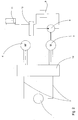
- FIG. 1 shows a schematic circuit diagram for a mobile work machine according to the prior art.
- Leads 2 lead from the voltage source 1 to an electrical control 3.
- Two motors 4, 5 and an electrical energy store 6 and a braking resistor 7 are connected to the control 3.
- the motor 4 serves as the drive for the mobile machine.
- the motor 5 drives a hydraulic pump 8 of a hydraulic circuit.
- This pump conveys the hydraulic fluid from a container 9 to a control valve block 10.
- the supply of hydraulic consumers is regulated via the control valve block 10. In the present exemplary embodiment, these are represented by the cylinder 11. Hydraulic fluid, which is not supplied to consumers, is supplied via a, in present case in the control valve block 10 integrated, pressure reducing valve derived to the container 9.
- the controller 3 If the mobile working machine is braked by the motor 4, this supplies current to the controller 3 in generator mode, which forwards it to the electrical energy store 6 or the braking resistor 7. If the electrical energy store 6 is fully charged, the energy can only be dissipated via the braking resistor 7, which converts it into heat and must therefore be adequately cooled.
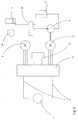
- FIG. 2 shows a particularly simple embodiment of a schematic circuit diagram for a mobile machine according to the invention.
- the same numbering was used in FIG. 1
- a new numbering was used for different components with a similar function, such as the electrical control 12 according to the invention.
- the voltage source 1 supplies the mobile work machine, in particular the controller 12, with electrical energy.
- the sources customary for mobile machines with their specific advantages can be used as voltage source 1.
- Internal combustion engines, for example, are simple and robust sources of energy, while fuel cells have a high degree of efficiency and favorable exhaust gas behavior, and a supply from the electricity network via cable offers practically unlimited operating time.
- the controller 12 can, as in the case shown, control both motors 4, 5 as a one-piece design, but separate controls for the individual motors 4, 5 are also possible, which are arranged spatially separated and, possibly via a third control unit, with one another Active connection.
- the designs customary for mobile work machines, for example for operation with direct current, alternating current or three-phase current, are used as motors.
- the commands for controlling the driving motor 4 are preferably received by the control 12 from operating elements (not shown here), such as an accelerator pedal, or an electronic control, while the motor 5 is preferably dependent on the operating state; in particular the liquid pressure of the hydraulic circuit is controlled.
- controller 12 If the mobile working machine is braked by the motor 4, this delivers current to the controller 12 according to the generator principle, which forwards it to the motor 5. In particular, when using fuel cell systems as voltage source 1, controller 12 also prevents current from being supplied to voltage source 1.
- the hydraulic pump driven by the motor 5 conveys the hydraulic fluid to the control valve block 10.
- the flow of the hydraulic fluid to the hydraulic consumers is regulated via this.
- these are represented by the cylinder 11; for example, an industrial truck can be a lifting and tilting cylinder of a lifting mast or a hydraulic steering actuation.
- the control valves for the individual consumers in the control valve block 10 can be actuated directly by an operator or via electronic controls.
- the hydraulic pump 8 supplies more hydraulic fluid than is required by the consumers 11, as will often also be the case during a braking operation, the excess fluid is fed into the container 9 via a pressure reduction valve and the energy is thus reduced.
- the pressure reduction valve is integrated in the control valve block 10, but can also be designed as a separate component.
- a memory for absorbing electrical energy as well as braking resistors can thus be completely dispensed with.
- the installation space for accommodating these units can thus be used for other purposes, and the effort for their maintenance and, especially for braking resistors, for cooling them is completely eliminated, so that the truck is as simple as possible.
- FIG. 3 shows a circuit diagram for a mobile working machine according to the invention with a hydrodynamic brake and an electrical energy store.
- an electrical energy store 13 which is in electrical connection with the electrical control 14, and a hydrodynamic braking device (retarder) 15 are also shown here ,
- the controller 14 if the hydraulic consumers do not need any power, preferably firstly leads it to the electrical energy store 13. It is preferably one or more capacitors large capacity, as they enable particularly fast charging compared to batteries. Due to the preferred charging of the electrical energy store 13, the electrical energy generated during braking is available again for the motors 4, 5 under renewed stress, while it is lost when it is converted into heat for the operation of the mobile working machine. As a result, the energy consumption of the mobile working machine is reduced compared to an embodiment without an electrical energy store 13, as is shown in FIG. 2. On the other hand, if the motor 5 needs energy during the braking process, since, for example, the hydraulic cylinder 11 is actuated at the same time, the energy generated during braking on the motor 4 is preferably supplied directly to the motor 5.
- the energy store 13 can also be discharged, preferably over the provision from the voltage source 1, in order to make sufficient capacity available again in the store 13 for the next braking operation.
- the control of the state of charge of the electrical energy store 13 is expediently matched to the requirement profile of the mobile work machine. For example, a minimum charge state of the electrical energy store during normal operation may also be desired in order to cover peak loads via the electrical energy store 13 and thereby be able to install a voltage source 1 of lower continuous power.
- the electrical energy store 13 is no longer able to absorb further energy or if this is not desired for other reasons, the energy will be released via the hydraulic circuit. This can be done using the hydraulic brake device 15 alone, using the pressure reducing valve alone, or using both options at the same time. Most of the time, the procedure will depend on the amount of energy to be implemented: degradation via both routes will preferably be selected for particularly large amounts of energy, while for medium amounts of energy the hydraulic braking device 15 usually Energy will be absorbed almost completely and with very low braking power, degradation can only be advantageous via the pressure reduction valve.
- the exemplary embodiment shown here is particularly suitable for mobile work machines with higher performance requirements, that is to say for heavy or fast-moving machines, in which the breakdown of the energy cannot be guaranteed entirely by means of a pressure reduction valve alone, since large amounts of energy are effectively reduced by means of the hydrodynamic braking device 15 become.
- the sole dissipation of the energy introduced into the hydraulic system via the hydrodynamic brake is also conceivable.
- Embodiments with a hydrodynamic brake but without an electrical energy store or without a hydrodynamic brake but with an electrical energy store are also possible.
Landscapes
- Engineering & Computer Science (AREA)
- Transportation (AREA)
- Structural Engineering (AREA)
- Mechanical Engineering (AREA)
- Life Sciences & Earth Sciences (AREA)
- Civil Engineering (AREA)
- Chemical & Material Sciences (AREA)
- Geology (AREA)
- Combustion & Propulsion (AREA)
- Power Engineering (AREA)
- Electric Propulsion And Braking For Vehicles (AREA)
- Arrangement Or Mounting Of Propulsion Units For Vehicles (AREA)
- Operation Control Of Excavators (AREA)
- Regulating Braking Force (AREA)
Applications Claiming Priority (2)
| Application Number | Priority Date | Filing Date | Title |
|---|---|---|---|
| DE10244769A DE10244769A1 (de) | 2002-09-26 | 2002-09-26 | Mobile Arbeitsmaschine |
| DE10244769 | 2002-09-26 |
Publications (1)
| Publication Number | Publication Date |
|---|---|
| EP1403130A2 true EP1403130A2 (fr) | 2004-03-31 |
Family
ID=31969596
Family Applications (1)
| Application Number | Title | Priority Date | Filing Date |
|---|---|---|---|
| EP03019247A Withdrawn EP1403130A2 (fr) | 2002-09-26 | 2003-08-26 | Véhicule de travail |
Country Status (4)
| Country | Link |
|---|---|
| US (1) | US7261170B2 (fr) |
| EP (1) | EP1403130A2 (fr) |
| JP (1) | JP2004120999A (fr) |
| DE (1) | DE10244769A1 (fr) |
Cited By (3)
| Publication number | Priority date | Publication date | Assignee | Title |
|---|---|---|---|---|
| EP1604853A2 (fr) | 2004-06-12 | 2005-12-14 | Jungheinrich Aktiengesellschaft | Unité d'entraínement pour une machine de travail, notamment pour un chariot de manutention |
| WO2017072241A1 (fr) * | 2015-10-29 | 2017-05-04 | Terex Mhps Gmbh | Chariot de manutention pour lourdes charges |
| EP2484878A3 (fr) * | 2011-02-02 | 2017-07-19 | STILL GmbH | Système frigorifique pour machine de travail mobile doté d'un entraînement à moteur à combustion électrique |
Families Citing this family (19)
| Publication number | Priority date | Publication date | Assignee | Title |
|---|---|---|---|---|
| US8765488B2 (en) * | 2004-07-22 | 2014-07-01 | The Board Of Trustees Of The University Of Illinois | Sensors employing single-walled carbon nanotubes |
| DE102004042288A1 (de) | 2004-08-30 | 2006-03-02 | Jungheinrich Ag | Batteriebetriebenes Flurförderzeug |
| JP2006273514A (ja) * | 2005-03-29 | 2006-10-12 | Toyota Industries Corp | ハイブリッド型フォークリフト |
| DE102005017734A1 (de) * | 2005-04-15 | 2006-10-19 | Zf Friedrichshafen Ag | Flurförderfahrzeug |
| FI118882B (fi) * | 2005-11-28 | 2008-04-30 | Ponsse Oyj | Menetelmä ja järjestely metsäkoneen tehonsiirrossa |
| JP4072183B1 (ja) * | 2006-11-09 | 2008-04-09 | 三菱重工業株式会社 | 作業車両および作業車両の動力制御方法 |
| DE102008011235A1 (de) * | 2008-02-26 | 2009-08-27 | Dbk David + Baader Gmbh | Temperaturregelanlage für Brennstoffzellen und Verfahren zur Temperaturregelung von Brennstoffzellen |
| US7938217B2 (en) * | 2008-03-11 | 2011-05-10 | Physics Lab Of Lake Havasu, Llc | Regenerative suspension with accumulator systems and methods |
| US8261865B2 (en) * | 2008-03-11 | 2012-09-11 | Physics Lab Of Lake Havasu, Llc | Regenerative suspension with accumulator systems and methods |
| US8807258B2 (en) | 2008-03-11 | 2014-08-19 | Physics Lab Of Lake Havasu, Llc | Regenerative suspension with accumulator systems and methods |
| US8008790B2 (en) * | 2008-12-19 | 2011-08-30 | Cnh America Llc | System for recovering or converting energy for equipment having a movable implement and method |
| ITBO20110226A1 (it) * | 2011-04-27 | 2012-10-28 | B P Battioni E Pagani S P A | Apparecchiatura per il sollevamento ed il trasporto di un carico. |
| US10112600B2 (en) | 2013-09-27 | 2018-10-30 | Liebherr-Components Biberach Gmbh | Self-propelling work machine and method for braking such a work machine |
| DE102013021608A1 (de) * | 2013-09-27 | 2015-04-02 | Liebherr-Components Biberach Gmbh | Selbstfahrende Arbeitsmaschine sowie Verfahren zum Abbremsen einer solchen Arbeitsmaschine |
| ITUB20152573A1 (it) | 2015-07-28 | 2017-01-28 | Cvs Ferrari S P A | Apparecchiatura per il sollevamento ed il trasporto di carichi, in particolare di corrispondenti containers |
| CN109910581A (zh) * | 2019-01-28 | 2019-06-21 | 合肥工业大学 | 电动汽车多动力源驱动与制动总成架构 |
| US12522491B2 (en) | 2021-09-15 | 2026-01-13 | Terex South Dakota, Inc. | Lift device and method of controlling on a grade |
| US12637341B2 (en) * | 2021-09-15 | 2026-05-26 | Terex South Dakota, Inc. | Lift device and method of controlling |
| DE202022105512U1 (de) * | 2022-09-29 | 2024-01-08 | Liebherr-Werk Nenzing Gmbh | Arbeitsmaschine |
Family Cites Families (10)
| Publication number | Priority date | Publication date | Assignee | Title |
|---|---|---|---|---|
| DE2824923C3 (de) * | 1978-06-07 | 1981-06-04 | Voith-Turbo Gmbh & Co Kg, 7180 Crailsheim | Bremsvorrichtung mit einer dynamischen und einer mechanischen Bremse |
| US5823280A (en) * | 1995-01-12 | 1998-10-20 | Nevcor, Inc. | Hybrid parallel electric vehicle |
| FR2732652B1 (fr) * | 1995-04-05 | 1997-05-16 | Techno Expres | Vehicule electro-hydraulique a recuperation d'energie |
| GB9602509D0 (en) * | 1996-02-07 | 1996-04-03 | Komatsu Uk Ltd | Control system for hydraulic drive |
| US5935035A (en) * | 1998-06-24 | 1999-08-10 | General Motors Corporation | Electro-mechanical powertrain |
| DE19955311C2 (de) * | 1999-11-17 | 2003-12-24 | Jungheinrich Ag | Antriebssystem für ein Flurförderzeug |
| DE19955313C2 (de) * | 1999-11-17 | 2003-12-18 | Jungheinrich Ag | Antriebssystem für Flurförderzeuge |
| US6664651B1 (en) * | 2000-11-14 | 2003-12-16 | Ford Motor Company | Engine on idle arbitration for a hybrid electric vehicle |
| JP3712684B2 (ja) * | 2001-06-01 | 2005-11-02 | 本田技研工業株式会社 | ハイブリッド車両の制御装置 |
| US6516905B1 (en) * | 2001-08-24 | 2003-02-11 | Ballard Power Systems Ag | Vehicle with a fuel cell system and method for operating the same |
-
2002
- 2002-09-26 DE DE10244769A patent/DE10244769A1/de not_active Withdrawn
-
2003
- 2003-08-26 EP EP03019247A patent/EP1403130A2/fr not_active Withdrawn
- 2003-09-19 US US10/664,406 patent/US7261170B2/en not_active Expired - Fee Related
- 2003-09-26 JP JP2003335689A patent/JP2004120999A/ja active Pending
Cited By (5)
| Publication number | Priority date | Publication date | Assignee | Title |
|---|---|---|---|---|
| EP1604853A2 (fr) | 2004-06-12 | 2005-12-14 | Jungheinrich Aktiengesellschaft | Unité d'entraínement pour une machine de travail, notamment pour un chariot de manutention |
| DE102004028620B4 (de) * | 2004-06-12 | 2008-02-21 | Jungheinrich Ag | Antriebssystem für eine mobile Arbeitsmaschine mit angetriebenen Rädern, insbesondere ein Flurförderzeug |
| EP2484878A3 (fr) * | 2011-02-02 | 2017-07-19 | STILL GmbH | Système frigorifique pour machine de travail mobile doté d'un entraînement à moteur à combustion électrique |
| WO2017072241A1 (fr) * | 2015-10-29 | 2017-05-04 | Terex Mhps Gmbh | Chariot de manutention pour lourdes charges |
| US10457534B2 (en) | 2015-10-29 | 2019-10-29 | Konecranes Global Corporation | Heavy-duty lift truck |
Also Published As
| Publication number | Publication date |
|---|---|
| US7261170B2 (en) | 2007-08-28 |
| DE10244769A1 (de) | 2004-04-08 |
| US20040124020A1 (en) | 2004-07-01 |
| JP2004120999A (ja) | 2004-04-15 |
Similar Documents
| Publication | Publication Date | Title |
|---|---|---|
| DE10244769A1 (de) | Mobile Arbeitsmaschine | |
| EP3049270B1 (fr) | Engin de travail automoteur et procédé de freinage d'un tel engin de travail | |
| EP1974979B1 (fr) | Chariot de manutention doté d'un entraînement hybride | |
| WO2020007751A1 (fr) | Procédé servant à faire fonctionner un système d'entraînement pour un engin de travail, système d'entraînement et engin de travail | |
| DE102010028972A1 (de) | Motorantriebssystem für ein Hybridfahrzeug und Verfahren zum Steuern desselben | |
| WO2013004799A2 (fr) | Véhicule à entraînement électrique pourvu de plusieurs accumulateurs d'énergie électrique | |
| WO2011103987A2 (fr) | Système d'entraînement et machine de travail | |
| EP3990308A1 (fr) | Véhicule présentant une pièce de véhicule électroconductrice pouvant être utilisée comme élément de résistance pour convertir de l'énergie électrique en chaleur | |
| DE102004010988A1 (de) | Hybridantriebssystem für einen Portalhubstapler | |
| DE102010022601A1 (de) | Kran mit Zusatzaggregat | |
| DE3525107A1 (de) | Antriebs- und betriebsbremsanlage von kraftfahrzeugen | |
| EP1748183B1 (fr) | Dispositif électrique de réglage des aubes de rotor d'une éolienne | |
| DE102010025266A1 (de) | Transportfahrzeug mit einer Mehrzahl elektrischer Maschinen | |
| EP2256013B1 (fr) | Système d'entraînement hybride pour véhicules ferroviaires | |
| EP3778285A1 (fr) | Système d'entraînement d'un véhicule électrique-diesel | |
| EP3315346B1 (fr) | Outil de travail doté d'un moteur d'entraînement électrique | |
| DE3911531A1 (de) | Hydraulik-system fuer kraftfahrzeuge | |
| EP1412218B1 (fr) | Systeme moteur hybride et procede de regulation de ce systeme moteur hybride | |
| EP4368433B1 (fr) | Circuit de fluide de refroidissement pour engin de travail autopropulsé comprenant plusieurs composants de propulsion électrique | |
| EP1636059B1 (fr) | Autopompe avec systeme d'entrainement, et procede de commande du systeme d'entrainement | |
| EP2657058A2 (fr) | Véhicule utilitaire | |
| DE19816777C2 (de) | Energiemanagementsystem für Mehrkomponentenantrieb | |
| DE102023204120A1 (de) | Verfahren zum Betreiben eines Batteriesystems | |
| DE102022212922A1 (de) | Antriebssystem für ein Fahrzeug und Betriebsverfahren | |
| DE102016002652A1 (de) | Steuervorrichtung und Verfahren zum Koordinieren eines Betriebs zumindest zweier elektrischer Nebenaggregate eines Kraftfahrzeugs |
Legal Events
| Date | Code | Title | Description |
|---|---|---|---|
| PUAI | Public reference made under article 153(3) epc to a published international application that has entered the european phase |
Free format text: ORIGINAL CODE: 0009012 |
|
| AK | Designated contracting states |
Kind code of ref document: A2 Designated state(s): AT BE BG CH CY CZ DE DK EE ES FI FR GB GR HU IE IT LI LU MC NL PT RO SE SI SK TR |
|
| AX | Request for extension of the european patent |
Extension state: AL LT LV MK |
|
| STAA | Information on the status of an ep patent application or granted ep patent |
Free format text: STATUS: THE APPLICATION IS DEEMED TO BE WITHDRAWN |
|
| 18D | Application deemed to be withdrawn |
Effective date: 20060302 |