EP1403155A2 - Moteur symétrique pour éléments d'essuie-glaces - Google Patents
Moteur symétrique pour éléments d'essuie-glaces Download PDFInfo
- Publication number
- EP1403155A2 EP1403155A2 EP03005912A EP03005912A EP1403155A2 EP 1403155 A2 EP1403155 A2 EP 1403155A2 EP 03005912 A EP03005912 A EP 03005912A EP 03005912 A EP03005912 A EP 03005912A EP 1403155 A2 EP1403155 A2 EP 1403155A2
- Authority
- EP
- European Patent Office
- Prior art keywords
- gear
- drive unit
- motor
- drive
- systems according
- Prior art date
- Legal status (The legal status is an assumption and is not a legal conclusion. Google has not performed a legal analysis and makes no representation as to the accuracy of the status listed.)
- Withdrawn
Links
Images



Classifications
-
- F—MECHANICAL ENGINEERING; LIGHTING; HEATING; WEAPONS; BLASTING
- F16—ENGINEERING ELEMENTS AND UNITS; GENERAL MEASURES FOR PRODUCING AND MAINTAINING EFFECTIVE FUNCTIONING OF MACHINES OR INSTALLATIONS; THERMAL INSULATION IN GENERAL
- F16H—GEARING
- F16H1/00—Toothed gearings for conveying rotary motion
- F16H1/28—Toothed gearings for conveying rotary motion with gears having orbital motion
- F16H1/32—Toothed gearings for conveying rotary motion with gears having orbital motion in which the central axis of the gearing lies inside the periphery of an orbital gear
-
- B—PERFORMING OPERATIONS; TRANSPORTING
- B60—VEHICLES IN GENERAL
- B60S—SERVICING, CLEANING, REPAIRING, SUPPORTING, LIFTING, OR MANOEUVRING OF VEHICLES, NOT OTHERWISE PROVIDED FOR
- B60S1/00—Cleaning of vehicles
- B60S1/02—Cleaning windscreens, windows or optical devices
- B60S1/04—Wipers or the like, e.g. scrapers
- B60S1/06—Wipers or the like, e.g. scrapers characterised by the drive
- B60S1/08—Wipers or the like, e.g. scrapers characterised by the drive electrically driven
-
- B—PERFORMING OPERATIONS; TRANSPORTING
- B60—VEHICLES IN GENERAL
- B60S—SERVICING, CLEANING, REPAIRING, SUPPORTING, LIFTING, OR MANOEUVRING OF VEHICLES, NOT OTHERWISE PROVIDED FOR
- B60S1/00—Cleaning of vehicles
- B60S1/02—Cleaning windscreens, windows or optical devices
- B60S1/04—Wipers or the like, e.g. scrapers
- B60S1/06—Wipers or the like, e.g. scrapers characterised by the drive
- B60S1/16—Means for transmitting drive
- B60S1/166—Means for transmitting drive characterised by the combination of a motor-reduction unit and a mechanism for converting rotary into oscillatory movement
-
- B—PERFORMING OPERATIONS; TRANSPORTING
- B60—VEHICLES IN GENERAL
- B60S—SERVICING, CLEANING, REPAIRING, SUPPORTING, LIFTING, OR MANOEUVRING OF VEHICLES, NOT OTHERWISE PROVIDED FOR
- B60S1/00—Cleaning of vehicles
- B60S1/02—Cleaning windscreens, windows or optical devices
- B60S1/04—Wipers or the like, e.g. scrapers
- B60S1/06—Wipers or the like, e.g. scrapers characterised by the drive
- B60S1/16—Means for transmitting drive
- B60S1/18—Means for transmitting drive mechanically
- B60S1/26—Means for transmitting drive mechanically by toothed gearing
-
- H—ELECTRICITY
- H02—GENERATION; CONVERSION OR DISTRIBUTION OF ELECTRIC POWER
- H02K—DYNAMO-ELECTRIC MACHINES
- H02K7/00—Arrangements for handling mechanical energy structurally associated with dynamo-electric machines, e.g. structural association with mechanical driving motors or auxiliary dynamo-electric machines
- H02K7/10—Structural association with clutches, brakes, gears, pulleys or mechanical starters
- H02K7/116—Structural association with clutches, brakes, gears, pulleys or mechanical starters with gears
-
- F—MECHANICAL ENGINEERING; LIGHTING; HEATING; WEAPONS; BLASTING
- F16—ENGINEERING ELEMENTS AND UNITS; GENERAL MEASURES FOR PRODUCING AND MAINTAINING EFFECTIVE FUNCTIONING OF MACHINES OR INSTALLATIONS; THERMAL INSULATION IN GENERAL
- F16H—GEARING
- F16H1/00—Toothed gearings for conveying rotary motion
- F16H1/28—Toothed gearings for conveying rotary motion with gears having orbital motion
- F16H2001/2881—Toothed gearings for conveying rotary motion with gears having orbital motion comprising two axially spaced central gears, i.e. ring or sun gear, engaged by at least one common orbital gear wherein one of the central gears is forming the output
Definitions
- Vehicle wipers are used to clean sight, headlight and mirror wipers.
- the wipers are usually driven by electric drives and various types of gear which interact with the electric drives, such as wiper linkages.
- wiper linkages In the case of rear window wipers on motor vehicles, a single wiper is usually used today, while two-armed window wipers are used for cleaning front windows on road or rail vehicles. If two motors are used to drive the windscreen wipers, different versions are usually required for the drives, both on the driver and the passenger side of the vehicle.
- a wiper system on a vehicle is driven by a wiper drive.
- the wiper system comprises a tube plate which receives the wiper drive with a drive shaft guided in a bearing socket.
- the wiper drive is inserted with the bearing socket into a tubular element arranged on the tube board.
- the tubular element is molded onto the tube board, the bearing socket of the wiper drive being inserted through the tube board.
- the wiper drive is fixed in the circumferential direction by frictional connection between the bearing socket and the tubular element on the tube board, but can also be fixed in the circumferential direction between the bearing socket and the tubular element by positive locking.
- the tubular element can have an inner contour that deviates from the circular shape, in particular a polygonal or non-circular one, with an appropriate outer contour of the Bearing neck corresponds.
- a fixation between the bearing socket of the wiper drive and the tubular element can also be done via a toothing.
- worm gears Due to the compulsory, principle-related offset of the drive and drive axles of a worm gear, it is necessary to create different receptacles for this type of gear for both the driver and the passenger side.
- worm gears require a relatively large amount of installation space due to the forced misalignment of the input and output shafts.
- a wiper drive which can be integrated in particular into hollow shafts. Due to the mirror-symmetrical structure of the proposed wiper drive, the output axis of this wiper drive lies in the mirror plane or the output axis lies in the center of the rotationally symmetrical component. If the output axis of the wiper drive is used directly to drive a wiper or wiper arm, an extremely compact direct wiper drive (WDA) is created.
- WDA direct wiper drive
- the mirror-symmetrical structure of the wiper drive proposed according to the invention offers considerable advantages with regard to the installation space required and enables cost savings.
- connection concept with regard to the use of mirror-symmetrically constructed wiper drives or direct wiper drives can be standardized and thus the application design - for example at the automobile manufacturer - and installation can be considerably simplified. Rationalization effects or rationalization potential in the solution proposed according to the invention can be seen above all in the fact that by using the same construction methods for different drives - be it front and rear wipers or headlight wipers - identical components can be used. If the wiper drive used is a rotationally symmetrical component and teachable electronics, which can optionally include position detection, all wiper drives can be further simplified during installation, since the drive and wiper arm or another wiper arm component can be in any position relative to one another during assembly is. With regard to the installation in the final assembly, this makes installation considerably easier, since on the one hand a shorter installation and a shorter cycle time can be achieved and on the other hand fewer installation errors can occur.
- Figure 1.1 to 1.3 shows a plan view, a side view and a rear view of a rotationally symmetrical wiper drive.
- a rotationally symmetrical drive unit 1 comprises a BPM (Brushless Permanent Magnet) motor, which is an electronically commutated, brushless electric motor with permanent magnets without switched reluctance.
- BPM Batteryless Permanent Magnet
- Electronically commutated (EC motors) are particularly interesting as rotationally symmetrical drive units 1, because alternative designs are possible, which are often interesting because of the available space. This allows these rotationally symmetrical drives 1 to be designed relatively flat with a large diameter.
- the electronics of such EC motors can be very easily connected to the data buses (CAN data buses) of the motor vehicle; there is no additional circuitry. Since the EC motors have no brushes due to their design principle, there is therefore no wear on these components, which is advantageous for frequently running motors.
- the rotationally symmetrical drive 1 comprises a first housing shell 2 and a second housing shell 3, which are connected to one another along a ring-shaped joint 4.
- the output shaft of the rotationally symmetrical drive 1 is identified by reference numeral 5 and passes through the first housing shell 2.
- the output shaft 5 of the rotationally symmetrical drive unit 1 is enclosed by a hollow output shaft 6.
- the connection points 7, 8 and 9 are each flush with one another at an angle of 120 ° to one another on the outer circumferences of both the first housing shell 2 and the second housing shell 3.
- the connection points 7, 8 and 9 each include a bore 10 and flush with the Joints 7, 8 and 9 on the first housing shell 1 recesses 11.
- a sensor element 12 is arranged on the rear side of the second housing shell 3.
- This sensor element 12 can be designed, for example, as an AMR sensor element, which at the same time represents a rotationally symmetrical connection point 27 for control and regulating electronics, which is indicated in the side view according to FIG. 1.2. If the control and regulating electronics that can be connected to the rotationally symmetrical drive unit 1 are configured as electronics capable of learning (optionally with position detection), additional simplifications can be achieved when installing the rotationally symmetrical drive unit 1 shown in FIG.
- the side view according to FIG. 1.2 of the rotationally symmetrical drive unit 1 also shows that in the region of an end face of the first housing shell 2, seen in the circumferential direction of the first housing shell 2, contact surfaces 7, 8 and 9 correspondingly designed are arranged.
- the rotationally symmetrical drive unit 1 can be mounted on a bulkhead or an end wall on the driver and passenger side of a motor vehicle body via this contact surface, optionally with the interposition of a sealing element not shown in FIG. 1.2.
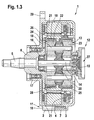
- Figure 1.3 shows a sectional view of a rotationally symmetrical drive that can be used as a wiper drive.
- first housing shell 2 and the second housing shell 3 of the rotationally symmetrical drive unit 1 enclose an integrated planetary gear 13.
- a shaft 14 is rotatably received in a first bearing 15 and a second bearing 16.
- the first bearing 15 is in the second Housing shell 3, while the second bearing 16 is received inside a hollow output shaft 6.
- connection points 7, 8, 9 shown in FIGS. 1.1 and 1.2, of which only the first connection point 7 is shown here.
- the connection points of the first and second housing shells joined to each other at the joint 4 can also be designed as flange bores, as shown in the upper area of FIG. 1.3. According to the flange pattern of the rotationally symmetrical drive unit 1 as shown in FIG.
- connecting points 29 of the rotationally symmetrical drive unit 1 can be implemented in a standardized manner with the motor vehicle body and can be designed identically on the driver and front passenger sides of the motor vehicle body, which simplifies the assembly effort and furthermore a larger one Freedom in the handling of the rotationally symmetrical drive unit 1 when it is installed in the area in which the engine and passenger compartment of a vehicle adjoin one another is permitted. Furthermore, the handling of a rotationally symmetrical drive unit 1 during assembly on a vehicle window can be improved considerably.
- the hollow output shaft 6 in turn is mounted in the first housing shell 2 by means of a hollow shaft bearing 17. Via a peg 18, a first ring gear 19 is rotatably received on the hollow output shaft 6 and is designed with a ring-shaped internal toothing.
- the internal toothing of the first ring gear 19 meshes with first planet gears 22, which are received on a planet gear shaft 24.
- the planet gear shaft 24 in turn is mounted in a carrier disk 20 which is received on the shaft 14 and is provided on its outer circumference with a ring 28 which acts as a rotor and is equipped with magnets.
- the ring 28 forms the rotor.
- the stator of the rotationally symmetrical drive unit 1 as shown in FIG. 1.3 is formed by windings 21 arranged in a rotationally fixed manner inside the first housing shell 2.
- second planet gears 23 are accommodated, which are designed with a somewhat enlarged diameter.
- the second planet gears 23 can also have a diameter corresponding to the first planet gears 23 or another diameter.
- the second ring gear 25 is regarding of its pitch circle diameter matched to the respective diameter of the second planet gears 23.
- the second ring gear 25 is accommodated in a rotationally fixed manner within the second housing shell 3.
- a return ring for the hollow output shaft 6 is designated.
- connection 27 for the control electronics is located inside the sensor element 12 on the rear end face of the second housing shell 3. This is also coaxial with the axis of symmetry of the output shaft 5 and the shaft 14 of the integrated planetary gear 13, so that the control electronics for the rotationally symmetrical drive unit 1 can be designed identically on the driver and front passenger side without additional effort according to the sectional view in FIG. 1.3.
- Figure 2 shows a cross section through a space-saving rotationally symmetrical crown gear.
- the rotationally symmetrical drive unit 30 is designed according to the embodiment variant according to FIG. 2 as an electric drive with an integrated planetary gear.
- the planetary gear 30 comprises crown wheels of a rotationally symmetrical drive unit.
- the planetary gear 30 with crown wheels comprises an electric drive 31.
- the electric drive 31 comprises a stator 42 which is opposed by a rotor 39.
- a first planet gear 34 and a second planet gear 35 are received on a common planet gear shaft 36.
- the planet gear shaft 36 is rotatably received on the one hand in a jacket 38 and on the other hand in a hub 37.
- the first planet gears 34 mesh with the teeth of a first crown gear 32, while the second planet gears 35 mesh with the teeth of a second crown gear 33.
- the first crown wheel 32 is integrated within a housing cover 43, within which an output shaft 40, rotatably received by a roller bearing, is arranged.
- the first crown gear 32 serves as a drive crown gear
- the second crown gear 33 is rotatably received on the output shaft 40 and is driven via the second planet gears 35, which act as output pinions and are received on the common planet gear shaft 36.
- the second crown wheel 33 rotates at the output speed.
- the axis of rotation, about which the first and second planet gears 34 and 35 rotate, is identified by reference numeral 46
- a second axis of rotation of the output shaft 40 which coincides with the axis of rotation of the second crown gear 33
- the first axis of rotation 46 coincides with the axis of symmetry of the planet gear shaft 36
- the second axis of rotation 47 coincides with the line of symmetry of the output shaft 40.
- Control units 44 are mounted in a further cover element opposite the housing cover 43.
- a cooling fin 45 is also provided on this cover element, which serves to dissipate the heat generated.
- a bearing sleeve 41 is accommodated in the further cover element, which surrounds the second axis of rotation 47.
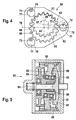
- FIG. 3 shows a schematic illustration of a rotationally symmetrical shaft gear.
- the rotationally symmetrical drive unit 1 can comprise a wave gear 50.
- Shaft gears 50 are particularly suitable for rotationally symmetrical drives, because they themselves are constructed symmetrically, the drive and driven axes running coaxially with one another.
- Shaft gearboxes 50 are very compact, whereby a very wide reduction band is made available (from approx. 1:30 to approx. 1: 300).
- wave gears 50 are designed to be self-locking.
- This embodiment variant of a rotationally symmetrical drive unit 1 also permits identical connection points on the front bulkhead of a motor vehicle body and considerably increases the degrees of freedom when mounting as a wiper drive.
- the wave gear 50 according to the schematic representation in Figure 3 comprises an output shaft 5 which is coaxial with the motor shaft of an electric drive, not shown in Figure 3.
- the wave gear 50 comprises a first housing shell 2 and a second housing shell 3, the first housing shell 2 being removed from the second housing shell 3 in the illustration according to FIG.
- the end face of the wave gear 50 resting on a body wall below the windshield of the motor vehicle is identified by reference number 51.
- FIG. 4 shows a schematic illustration of a circular thrust gear with a ring gear toothing which cooperates with an output spur gear.
- a circular thrust gear 60 comprises a thrust plate 61.
- a ring gear toothing 62 In the thrust plate 61 there is a ring gear toothing 62, the pitch circle of which is identified by reference numeral 63.
- the center of the ring gear toothing 62 in the interior of the thrust plate 61 is identified by reference numeral 64.
- the ring gear toothing 62 of the thrust plate 61 meshes with an output shaft 65, the axis of rotation 67 of which at a distance 70 eccentrically to the center 64 of the ring gear teeth 62 is arranged.
- the direction of rotation of the output shaft 65 with respect to its axis of rotation 67 is indicated by arrow 69.
- an external toothing 66 On the outside of the output shaft 65, an external toothing 66 is formed, the pitch circle of which is identified by reference numeral 68.
- the thrust plate 61 of the circular thrust gear 60 is movably received on a first crank 71, a second crank 72 and a third crank 73.
- the crank pins of the cranks 71, 72, 73 each lie on the inner sides 77 of openings 74, 75, 76 - which are designed as bores - of the thrust plate 61.
- the direction of rotation in which the cranks 71, 72, 73 are moved is indicated by the arrows above the crank pin of the cranks 71, 72, 73 in FIG. 4.
- Reference number 78 denotes a mirror plane which runs through the center 64 of the ring gear toothing 62 in the thrust plate 61 and runs through an eccentric axis center of one of the three cranks 71, 72, 73, in this case through the eccentric axis center of the second crank 72, which in this Trap serves as a drive crank.
- a high reduction ratio can be achieved with the circular thrust gear 60 shown schematically in FIG. 4, so that the use of a direct current motor (DC drive) is made possible and long drive trains with a large number of transmission components can be saved. This is favorable with regard to the space requirements of a wiper system drive below the windshield for applications in motor vehicles.
- DC drive direct current motor
- Figure 5 shows an axial swash plate gear
- An axial swash plate gear designated by reference numeral 80 in FIG. 5 comprises a housing 81 which accommodates the gear components.
- the housing 81 of the axial wobble mechanism 80 surrounds a swash plate 82.
- the swash plate 82 is guided on the one hand in a swash plate guide 85 which is fixed to the housing and which forces the swash plate 82 to move.
- the swash plate 82 is also received by means of a swash plate bearing 83 on a drive 86 with an angled eccentric.
- the swash plate which is provided with a toothing on an end face facing an output gear 87, is in meshing engagement 88 with it, as a result of which the output axis 84 is moved.
- the axial swash plate or swash gear 80 has characteristics similar to a radially acting swash plate or swash gear.
- Swash plate or swash wheel gears are understood here to mean both axial and radial swash plate gears. Both versions of a swash plate or swash gear are common that they have high power density combined with a large variety of gear reduction.
- swash plate or swash gear 80 have an extremely simple structure, which makes them very robust, and good efficiency. Thereafter, wobble wheel or swash plate gears 80 are rotationally symmetrical, so that they can be integrated very well into the interior of a hollow output shaft 6 (see FIG. 1.3).
- FIGS. 6.1 and 6.2 A straight-toothed crown gear is shown in FIGS. 6.1 and 6.2.
- a rotationally symmetrical design of a wiper system drive cannot be achieved in principle, since the pinion shaft 95 of the electric drive 91 runs at an angle of 90 ° - here perpendicular to the plane of the drawing - to the axis of rotation 97 of a crown wheel segment 98.
- the crown wheel gear arrangement 90 shown in FIGS. 6.1 and 6.2 has considerable advantages due to its compact design compared to the use of a worm gear on which the drive and driven axes are also, for reasons of principle, also staggered by an angle of 90 ° to one another.
- a very compact design is achieved by the articulation of the crown wheel segment 96 directly on the housing 92 of the electric drive 91.
- the motor / gear unit 90, 91 can be mirror-symmetrical to the mirror plane 78 shown in FIG. 6.2.
- the arrangement of a motor gearbox unit for wiper systems shown in FIGS. 6.1 and 6.2 offers the advantage that in relation to a driver or a passenger side on a bulkhead below the assembly area of the windshield of a motor vehicle body, it is only necessary to twist the motor / gear arrangement 90 or 91 about its axis of symmetry 93, which considerably simplifies their installation.
- the crown gear 90 includes an electric drive 91 which can be designed as a DC motor, as an asynchronous or as a transverse flux motor. This is enclosed by a housing 92, which is rotationally symmetrical to the axis of symmetry 93. Due to the 90 ° orientation of the axis of rotation 97, which represents the output axis of the crown gear 90, and the pinion shaft 94 of the electric drive 91, a mirror-symmetrical construction of this motor / gear arrangement can be achieved.
- the crown gear segment 96 which pivots about the articulation point 97, which coincides with the output shaft of the crown gear 90, sweeps over a pivot angle of approximately 100 ° to 120 °. If the crown gear segment 96 is provided with a toothing 98, this is preferably formed as a degree toothing which meshes with the pinion 95 embodied on the motor shaft 94.
- the drives shown in Figures 1.1, 1.2, 1.3 and 3 and 5 are essentially rotationally symmetrical. These design variants of the wiper system drives proposed according to the invention facilitate the connection to the vehicle body, since the connection points (cf. positions 7, 8 and 9 in FIGS. 1.1, 1.2 and 1.3) can simply be copied. Accordingly, these can be designed identically on the driver and passenger side below a windshield in the body area of a vehicle body. A standardized connection requires little application effort.
- rotationally symmetrical drive units the output shaft 5 of which can be used directly to drive a wiper arm
- rotationally symmetrical drives 1 in two-motor systems or in direct wiper drives, the same drives can be used for the driver and front passenger. This means that the same components, the same flange patterns and the same standardized connection points can be formed on the driver and passenger side.
- the electrics or electronics of the drives with regard to connector design, control and regulation electronics and the connection to the vehicle electrical system or to a vehicle bus system (CAN bus) can be considerably simplified, since these interfaces and the components used can be designed identically.
- a mirror-symmetrical arrangement of a wiper drive unit is possible if the output axis - as shown - lies in the mirror plane 78.
- This can considerably simplify the assembly of such mirror-symmetrically constructed wiper drive units, since for mounting on the driver or passenger side below a windshield in the front region of a motor vehicle body, only a rotation of the drive units 60 and 90 about their axes of symmetry (cf. 93 according to FIGS. 6.1 and 6.2) is required and the other connection components, such as connection point for on-board electrical system voltage, connection point of the bus system (CAN data bus), control and regulating electronics, can otherwise be designed identically.
Landscapes
- Engineering & Computer Science (AREA)
- Mechanical Engineering (AREA)
- General Engineering & Computer Science (AREA)
- Power Engineering (AREA)
- Connection Of Motors, Electrical Generators, Mechanical Devices, And The Like (AREA)
Applications Claiming Priority (2)
| Application Number | Priority Date | Filing Date | Title |
|---|---|---|---|
| DE10245663 | 2002-09-30 | ||
| DE2002145663 DE10245663A1 (de) | 2002-09-30 | 2002-09-30 | Symmetrischer Antrieb für Wischerkomponenten |
Publications (2)
| Publication Number | Publication Date |
|---|---|
| EP1403155A2 true EP1403155A2 (fr) | 2004-03-31 |
| EP1403155A3 EP1403155A3 (fr) | 2005-04-20 |
Family
ID=31969719
Family Applications (1)
| Application Number | Title | Priority Date | Filing Date |
|---|---|---|---|
| EP03005912A Withdrawn EP1403155A3 (fr) | 2002-09-30 | 2003-03-17 | Moteur symétrique pour éléments d'essuie-glaces |
Country Status (3)
| Country | Link |
|---|---|
| US (1) | US6727614B2 (fr) |
| EP (1) | EP1403155A3 (fr) |
| DE (1) | DE10245663A1 (fr) |
Cited By (8)
| Publication number | Priority date | Publication date | Assignee | Title |
|---|---|---|---|---|
| EP1772948A1 (fr) * | 2005-10-10 | 2007-04-11 | Peter Ortloff | Moteur-réducteur avec un moteur-couple et un réducteur à transmission harmonique |
| EP1693597A3 (fr) * | 2005-02-22 | 2008-06-04 | Aisin Seiki Kabushiki Kaisha | Engranage hypocycloidal avec moteur intégré |
| WO2009141277A1 (fr) * | 2008-05-21 | 2009-11-26 | Valeo Systemes D'essuyage | Unité de commande externe pour entraînement auxiliaire électrique de véhicules, et entraînement auxiliaire électrique utilisant une telle unité de commande |
| EP2192672A2 (fr) | 2008-12-01 | 2010-06-02 | Ortloff, Helene | Moteur électrique avec réducteur en plastique |
| EP2072357A3 (fr) * | 2007-12-19 | 2010-10-27 | Robert Bosch Gmbh | Engrenage d'essuie-glace et installation d'essuie-glace dotée d'un engrenage d'essuie-glace |
| ITRM20090518A1 (it) * | 2009-10-09 | 2011-04-10 | Michele Baldin | Posizionatore o motore passo-passo basculante autobloccante dotato di sensori ad effetto di hall per il rilevamanto della posizione raggiunta e in grado di effettuare movimenti anche con un solo step |
| EP2626982A1 (fr) * | 2012-02-07 | 2013-08-14 | Siemens Aktiengesellschaft | Motoréducteur |
| WO2016184566A1 (fr) * | 2015-05-19 | 2016-11-24 | Knorr-Bremse Gesellschaft Mit Beschränkter Haftung | Entraînement d'essuie-glace d'un dispositif d'essuie-glace de véhicule automobile |
Families Citing this family (21)
| Publication number | Priority date | Publication date | Assignee | Title |
|---|---|---|---|---|
| EP1485636B1 (fr) * | 2002-03-13 | 2009-04-22 | Robert Bosch Gmbh | Mecanisme de commande |
| US7676880B2 (en) * | 2002-05-15 | 2010-03-16 | Trico Products Corporation | Direct drive windshield wiper assembly |
| US6944906B2 (en) * | 2002-05-15 | 2005-09-20 | Trico Products Corporation | Direct drive windshield wiper assembly |
| US7389561B2 (en) * | 2002-05-15 | 2008-06-24 | Trico Products Corporation | Tandem windshield wiper system with direct drive motor |
| JP2004052928A (ja) * | 2002-07-22 | 2004-02-19 | Nippon Soken Inc | 回転式アクチュエータ |
| US7316627B2 (en) * | 2004-08-27 | 2008-01-08 | Arvinmeritor Technology, Llc | Integrated two-speed motor |
| CZ301606B6 (cs) * | 2004-10-25 | 2010-04-28 | Iqi S.R.O. | Zpusob ovládání stírátek u automobilových steracových systému prostrednictvím rízení elektrického motoru s kývavým pohybem jeho výstupní hrídele a úprava tohoto elektrického motoru |
| CN101258664B (zh) * | 2005-09-09 | 2011-05-11 | 蒂姆肯公司 | 紧凑型轴向磁通电动机驱动装置 |
| US8358330B2 (en) * | 2005-10-21 | 2013-01-22 | True Vision Systems, Inc. | Stereoscopic electronic microscope workstation |
| FR2893575B1 (fr) * | 2005-11-23 | 2009-06-12 | Falgayras Sa Sa | Dispositif d'entrainement destine notamment a l'entrainement d'un essuie-glace |
| JP2007185021A (ja) * | 2006-01-05 | 2007-07-19 | Japan Servo Co Ltd | 変速機構付回転電機及びこれを用いた駆動装置 |
| US20100016114A1 (en) * | 2008-07-18 | 2010-01-21 | Din-Shan Chang | Modular robot control system |
| DE102011102749B4 (de) * | 2011-05-28 | 2020-11-12 | Volkswagen Aktiengesellschaft | Getriebeanordnung für ein Kraftfahrzeug |
| EP2730804B1 (fr) * | 2011-07-08 | 2022-01-12 | Sumitomo Heavy Industries, Ltd. | Engrenage réducteur épicycloïdal |
| DE102012212143B4 (de) * | 2012-04-20 | 2014-08-28 | Johnson Controls Gmbh | Verfahren und Vorrichtung zur Steuerung und/oder Regelung der elektromechanischen Aktuierung einer Planetengetriebeanordnung |
| DE102012105748A1 (de) | 2012-06-29 | 2014-01-02 | Valeo Systèmes d'Essuyage | Scheibenwischermotor |
| US8834311B1 (en) * | 2013-03-07 | 2014-09-16 | The United States Of America As Represented By The Secretary Of The Army | Concentric electric servomotor/gearbox drive |
| US9322635B2 (en) | 2013-07-08 | 2016-04-26 | Emerson Process Management, Valve Automation, Inc. | Absolute positions detectors |
| IT201600072537A1 (it) * | 2016-07-12 | 2018-01-12 | Phase Motion Control S P A | Motoriduttore |
| JP6571258B2 (ja) * | 2017-11-03 | 2019-09-04 | 台達電子工業股▲ふん▼有限公司Delta Electronics,Inc. | 動力源を有する減速機 |
| US10883548B2 (en) * | 2019-04-05 | 2021-01-05 | Schaeffler Technologies AG & Co. KG | Electric axle with differential sun gear disconnect clutch |
Family Cites Families (14)
| Publication number | Priority date | Publication date | Assignee | Title |
|---|---|---|---|---|
| GB623901A (en) * | 1947-05-24 | 1949-05-25 | Frederick Augustus Pinhay | Improvements in or relating to bevel gear drives |
| US2919588A (en) * | 1957-04-16 | 1960-01-05 | Edward V Sundt | Driving mechanism for windshield wipers and the like |
| DE8513219U1 (de) * | 1985-05-04 | 1986-05-22 | Heidelberger Druckmaschinen Ag, 6900 Heidelberg | Elektromotor mit damit gekoppeltem mechanischem Getriebe |
| DE3808771A1 (de) * | 1988-03-16 | 1989-03-16 | Thomas Ruehlemann | Waelzgetriebe |
| DE4312869C2 (de) * | 1993-04-20 | 1999-09-16 | Lothar Strach | Kreisschubgetriebe |
| FR2730204B1 (fr) * | 1995-02-08 | 1997-04-04 | Valeo Systemes Dessuyage | Motoreducteur, notamment pour l'entrainement d'un dispositif d'essuie-glace de vehicule |
| DE19508306A1 (de) * | 1995-03-09 | 1996-09-12 | Bosch Gmbh Robert | Antriebsaggregat mit einem elektrischen Antriebsmotorr und einem diesem nachgeordneten Schneckengetriebe |
| DE19532808C1 (de) * | 1995-08-25 | 1997-01-02 | Brose Fahrzeugteile | Antriebseinrichtung für bewegliche Bauteile in Kraftfahrzeugen |
| DE19642667A1 (de) | 1996-03-26 | 1997-10-02 | Bosch Gmbh Robert | Lagerung eines Wischerantriebs |
| DE29707039U1 (de) * | 1997-04-18 | 1998-08-13 | Hirn, Marliese, 72147 Nehren | Untersetzungsgetriebe |
| DE19748201C1 (de) * | 1997-10-31 | 1999-03-04 | Alber Ulrich Gmbh | Nabenantriebsvorrichtung |
| JP2001112215A (ja) * | 1999-10-05 | 2001-04-20 | Yaskawa Electric Corp | 減速機一体型アクチュエータ |
| DE19961054A1 (de) * | 1999-12-20 | 2001-06-28 | Voith Turbo Kg | Elektrische Antriebsvorrichtung, insbesondere Getriebemotor |
| JP2001286097A (ja) * | 2000-03-31 | 2001-10-12 | Asmo Co Ltd | モータ |
-
2002
- 2002-09-30 DE DE2002145663 patent/DE10245663A1/de not_active Ceased
-
2003
- 2003-03-17 EP EP03005912A patent/EP1403155A3/fr not_active Withdrawn
- 2003-05-22 US US10/443,726 patent/US6727614B2/en not_active Expired - Fee Related
Cited By (11)
| Publication number | Priority date | Publication date | Assignee | Title |
|---|---|---|---|---|
| EP1693597A3 (fr) * | 2005-02-22 | 2008-06-04 | Aisin Seiki Kabushiki Kaisha | Engranage hypocycloidal avec moteur intégré |
| EP1772948A1 (fr) * | 2005-10-10 | 2007-04-11 | Peter Ortloff | Moteur-réducteur avec un moteur-couple et un réducteur à transmission harmonique |
| EP2072357A3 (fr) * | 2007-12-19 | 2010-10-27 | Robert Bosch Gmbh | Engrenage d'essuie-glace et installation d'essuie-glace dotée d'un engrenage d'essuie-glace |
| WO2009141277A1 (fr) * | 2008-05-21 | 2009-11-26 | Valeo Systemes D'essuyage | Unité de commande externe pour entraînement auxiliaire électrique de véhicules, et entraînement auxiliaire électrique utilisant une telle unité de commande |
| EP2192672A2 (fr) | 2008-12-01 | 2010-06-02 | Ortloff, Helene | Moteur électrique avec réducteur en plastique |
| DE202009015389U1 (de) | 2008-12-01 | 2010-06-02 | Ortloff, Helene | Flextopfgetriebe |
| ITRM20090518A1 (it) * | 2009-10-09 | 2011-04-10 | Michele Baldin | Posizionatore o motore passo-passo basculante autobloccante dotato di sensori ad effetto di hall per il rilevamanto della posizione raggiunta e in grado di effettuare movimenti anche con un solo step |
| EP2626982A1 (fr) * | 2012-02-07 | 2013-08-14 | Siemens Aktiengesellschaft | Motoréducteur |
| WO2013117578A3 (fr) * | 2012-02-07 | 2013-10-24 | Siemens Aktiengesellschaft | Électroréducteur |
| WO2016184566A1 (fr) * | 2015-05-19 | 2016-11-24 | Knorr-Bremse Gesellschaft Mit Beschränkter Haftung | Entraînement d'essuie-glace d'un dispositif d'essuie-glace de véhicule automobile |
| US10843665B2 (en) | 2015-05-19 | 2020-11-24 | Knorr-Bremse Gesellschaft Mit Beschränkter Haftung | Windscreen wiper drive of a windscreen wiper device of a rail vehicle |
Also Published As
| Publication number | Publication date |
|---|---|
| EP1403155A3 (fr) | 2005-04-20 |
| DE10245663A1 (de) | 2004-04-08 |
| US6727614B2 (en) | 2004-04-27 |
| US20040061393A1 (en) | 2004-04-01 |
Similar Documents
| Publication | Publication Date | Title |
|---|---|---|
| EP1403155A2 (fr) | Moteur symétrique pour éléments d'essuie-glaces | |
| DE102009039164A1 (de) | Lenkvorrichtung, insbesondere für eine Hinterradlenkung | |
| DE102010035088A1 (de) | Radaufhängung für ein Kraftfahrzeug | |
| DE10003452A1 (de) | Elektromotor mit Umlaufgetriebe | |
| DE102007019324A1 (de) | Elektrische Servolenkvorrichtung | |
| EP0249808B1 (fr) | Transmission électrique pour véhicule automobile | |
| DE102021214426A1 (de) | Steer-by-wire-lenkvorrichtung | |
| DE102017005462A1 (de) | Antriebsvorrichtung für einen Kraftwagen, insbesondere für einen Personenkraftwagen | |
| DE19748201C1 (de) | Nabenantriebsvorrichtung | |
| EP1013534A1 (fr) | Direction assistée électrique en particulier pour véhicules à moteur | |
| EP2411251A1 (fr) | Entraînement auxiliaire par moteur électrique, en particulier entraînement pour essuie-glace | |
| DE102021124761A1 (de) | Radnabenantriebsvorrichtung und verfahren zu deren zusammenbauen | |
| DE19942818B4 (de) | Lenksäulenmodul für ein Kraftfahrzeug | |
| DE102019134880A1 (de) | Stellantrieb mit einem mehrstufigen Getriebe | |
| DE68903095T2 (de) | Lenkvorrichtung fuer die hinterraeder eines durch vier raeder gelenkten fahrzeuges. | |
| DE69109551T2 (de) | Getriebemotoreinrichtung zum Antrieb eines Fahrzeugzubehörs, insbesondere für Kraftfahrzeugschiebedach. | |
| EP2228293A2 (fr) | Système d'entraînement pour un véhicule léger, notamment pour vélo | |
| DE102020123965A1 (de) | Spindeltriebanordnung, Lenkeinheit und Fahrwerksaktuator | |
| DE102022114432A1 (de) | Türantriebsvorrichtung zum elektromotorischen Verstellen einer Fahrzeugtür | |
| DE2926598C2 (fr) | ||
| EP2125459A1 (fr) | Dispositif d'entraînement d'essuie-glace | |
| EP1747969B1 (fr) | Roue motrice | |
| EP3415356A1 (fr) | Module d'engrenage d'essieu | |
| DE4136955A1 (de) | Differentialgetriebe | |
| DE10142599A1 (de) | Lenksystem für Fahrzeuge |
Legal Events
| Date | Code | Title | Description |
|---|---|---|---|
| PUAI | Public reference made under article 153(3) epc to a published international application that has entered the european phase |
Free format text: ORIGINAL CODE: 0009012 |
|
| AK | Designated contracting states |
Kind code of ref document: A2 Designated state(s): AT BE BG CH CY CZ DE DK EE ES FI FR GB GR HU IE IT LI LU MC NL PT RO SE SI SK TR |
|
| AX | Request for extension of the european patent |
Extension state: AL LT LV MK |
|
| PUAL | Search report despatched |
Free format text: ORIGINAL CODE: 0009013 |
|
| AK | Designated contracting states |
Kind code of ref document: A3 Designated state(s): AT BE BG CH CY CZ DE DK EE ES FI FR GB GR HU IE IT LI LU MC NL PT RO SE SI SK TR |
|
| AX | Request for extension of the european patent |
Extension state: AL LT LV MK |
|
| RIC1 | Information provided on ipc code assigned before grant |
Ipc: 7H 02K 7/116 B Ipc: 7F 16H 1/28 B Ipc: 7B 60S 1/28 B Ipc: 7B 60S 1/16 B Ipc: 7B 60S 1/08 A |
|
| 17P | Request for examination filed |
Effective date: 20051020 |
|
| AKX | Designation fees paid |
Designated state(s): CZ DE ES FR GB IT |
|
| STAA | Information on the status of an ep patent application or granted ep patent |
Free format text: STATUS: THE APPLICATION IS DEEMED TO BE WITHDRAWN |
|
| 18D | Application deemed to be withdrawn |
Effective date: 20060523 |