EP1403452B1 - Ensemble de verrou pour portes sectionnelles - Google Patents
Ensemble de verrou pour portes sectionnelles Download PDFInfo
- Publication number
- EP1403452B1 EP1403452B1 EP20030077919 EP03077919A EP1403452B1 EP 1403452 B1 EP1403452 B1 EP 1403452B1 EP 20030077919 EP20030077919 EP 20030077919 EP 03077919 A EP03077919 A EP 03077919A EP 1403452 B1 EP1403452 B1 EP 1403452B1
- Authority
- EP
- European Patent Office
- Prior art keywords
- latch
- set according
- section door
- lock
- handle lock
- Prior art date
- Legal status (The legal status is an assumption and is not a legal conclusion. Google has not performed a legal analysis and makes no representation as to the accuracy of the status listed.)
- Expired - Lifetime
Links
- 238000005096 rolling process Methods 0.000 claims abstract description 13
- 230000007246 mechanism Effects 0.000 claims description 12
- 238000006073 displacement reaction Methods 0.000 claims description 10
- 230000008034 disappearance Effects 0.000 claims description 3
- 230000000903 blocking effect Effects 0.000 description 2
- 238000010276 construction Methods 0.000 description 2
- 230000002146 bilateral effect Effects 0.000 description 1
- 230000005540 biological transmission Effects 0.000 description 1
- 230000006835 compression Effects 0.000 description 1
- 238000007906 compression Methods 0.000 description 1
- 230000000694 effects Effects 0.000 description 1
- 238000009434 installation Methods 0.000 description 1
- 230000002452 interceptive effect Effects 0.000 description 1
- 230000002427 irreversible effect Effects 0.000 description 1
- 230000000670 limiting effect Effects 0.000 description 1
- 230000002829 reductive effect Effects 0.000 description 1
- 230000002441 reversible effect Effects 0.000 description 1
- 239000007787 solid Substances 0.000 description 1
Images


Classifications
-
- E—FIXED CONSTRUCTIONS
- E05—LOCKS; KEYS; WINDOW OR DOOR FITTINGS; SAFES
- E05B—LOCKS; ACCESSORIES THEREFOR; HANDCUFFS
- E05B65/00—Locks or fastenings for special use
- E05B65/0021—Locks or fastenings for special use for overhead or roll-up doors, e.g. garage doors
-
- E—FIXED CONSTRUCTIONS
- E05—LOCKS; KEYS; WINDOW OR DOOR FITTINGS; SAFES
- E05D—HINGES OR SUSPENSION DEVICES FOR DOORS, WINDOWS OR WINGS
- E05D15/00—Suspension arrangements for wings
- E05D15/16—Suspension arrangements for wings for wings sliding vertically more or less in their own plane
- E05D15/165—Details, e.g. sliding or rolling guides
-
- E—FIXED CONSTRUCTIONS
- E05—LOCKS; KEYS; WINDOW OR DOOR FITTINGS; SAFES
- E05B—LOCKS; ACCESSORIES THEREFOR; HANDCUFFS
- E05B47/00—Operating or controlling locks or other fastening devices by electric or magnetic means
- E05B47/0001—Operating or controlling locks or other fastening devices by electric or magnetic means with electric actuators; Constructional features thereof
- E05B2047/0014—Constructional features of actuators or power transmissions therefor
- E05B2047/0015—Output elements of actuators
- E05B2047/0016—Output elements of actuators with linearly reciprocating motion
-
- E—FIXED CONSTRUCTIONS
- E05—LOCKS; KEYS; WINDOW OR DOOR FITTINGS; SAFES
- E05B—LOCKS; ACCESSORIES THEREFOR; HANDCUFFS
- E05B47/00—Operating or controlling locks or other fastening devices by electric or magnetic means
- E05B47/0001—Operating or controlling locks or other fastening devices by electric or magnetic means with electric actuators; Constructional features thereof
- E05B47/0012—Operating or controlling locks or other fastening devices by electric or magnetic means with electric actuators; Constructional features thereof with rotary electromotors
-
- E—FIXED CONSTRUCTIONS
- E05—LOCKS; KEYS; WINDOW OR DOOR FITTINGS; SAFES
- E05B—LOCKS; ACCESSORIES THEREFOR; HANDCUFFS
- E05B53/00—Operation or control of locks by mechanical transmissions, e.g. from a distance
- E05B53/003—Operation or control of locks by mechanical transmissions, e.g. from a distance flexible
-
- E—FIXED CONSTRUCTIONS
- E05—LOCKS; KEYS; WINDOW OR DOOR FITTINGS; SAFES
- E05B—LOCKS; ACCESSORIES THEREFOR; HANDCUFFS
- E05B65/00—Locks or fastenings for special use
- E05B65/08—Locks or fastenings for special use for sliding wings
- E05B65/087—Locks or fastenings for special use for sliding wings the bolts sliding parallel to the wings
- E05B65/0876—Locks or fastenings for special use for sliding wings the bolts sliding parallel to the wings cooperating with the slide guide, e.g. the rail
-
- E—FIXED CONSTRUCTIONS
- E05—LOCKS; KEYS; WINDOW OR DOOR FITTINGS; SAFES
- E05D—HINGES OR SUSPENSION DEVICES FOR DOORS, WINDOWS OR WINGS
- E05D15/00—Suspension arrangements for wings
- E05D15/16—Suspension arrangements for wings for wings sliding vertically more or less in their own plane
- E05D15/24—Suspension arrangements for wings for wings sliding vertically more or less in their own plane consisting of parts connected at their edges
-
- E—FIXED CONSTRUCTIONS
- E05—LOCKS; KEYS; WINDOW OR DOOR FITTINGS; SAFES
- E05Y—INDEXING SCHEME ASSOCIATED WITH SUBCLASSES E05D AND E05F, RELATING TO CONSTRUCTION ELEMENTS, ELECTRIC CONTROL, POWER SUPPLY, POWER SIGNAL OR TRANSMISSION, USER INTERFACES, MOUNTING OR COUPLING, DETAILS, ACCESSORIES, AUXILIARY OPERATIONS NOT OTHERWISE PROVIDED FOR, APPLICATION THEREOF
- E05Y2900/00—Application of doors, windows, wings or fittings thereof
- E05Y2900/10—Application of doors, windows, wings or fittings thereof for buildings or parts thereof
- E05Y2900/106—Application of doors, windows, wings or fittings thereof for buildings or parts thereof for garages
-
- Y—GENERAL TAGGING OF NEW TECHNOLOGICAL DEVELOPMENTS; GENERAL TAGGING OF CROSS-SECTIONAL TECHNOLOGIES SPANNING OVER SEVERAL SECTIONS OF THE IPC; TECHNICAL SUBJECTS COVERED BY FORMER USPC CROSS-REFERENCE ART COLLECTIONS [XRACs] AND DIGESTS
- Y10—TECHNICAL SUBJECTS COVERED BY FORMER USPC
- Y10S—TECHNICAL SUBJECTS COVERED BY FORMER USPC CROSS-REFERENCE ART COLLECTIONS [XRACs] AND DIGESTS
- Y10S292/00—Closure fasteners
- Y10S292/32—Freight car door fasteners
-
- Y—GENERAL TAGGING OF NEW TECHNOLOGICAL DEVELOPMENTS; GENERAL TAGGING OF CROSS-SECTIONAL TECHNOLOGIES SPANNING OVER SEVERAL SECTIONS OF THE IPC; TECHNICAL SUBJECTS COVERED BY FORMER USPC CROSS-REFERENCE ART COLLECTIONS [XRACs] AND DIGESTS
- Y10—TECHNICAL SUBJECTS COVERED BY FORMER USPC
- Y10S—TECHNICAL SUBJECTS COVERED BY FORMER USPC CROSS-REFERENCE ART COLLECTIONS [XRACs] AND DIGESTS
- Y10S292/00—Closure fasteners
- Y10S292/36—Overhead door latches
-
- Y—GENERAL TAGGING OF NEW TECHNOLOGICAL DEVELOPMENTS; GENERAL TAGGING OF CROSS-SECTIONAL TECHNOLOGIES SPANNING OVER SEVERAL SECTIONS OF THE IPC; TECHNICAL SUBJECTS COVERED BY FORMER USPC CROSS-REFERENCE ART COLLECTIONS [XRACs] AND DIGESTS
- Y10—TECHNICAL SUBJECTS COVERED BY FORMER USPC
- Y10T—TECHNICAL SUBJECTS COVERED BY FORMER US CLASSIFICATION
- Y10T292/00—Closure fasteners
- Y10T292/08—Bolts
- Y10T292/0801—Multiple
- Y10T292/0825—Hooked end
- Y10T292/0826—Operating means
- Y10T292/083—Flexible
-
- Y—GENERAL TAGGING OF NEW TECHNOLOGICAL DEVELOPMENTS; GENERAL TAGGING OF CROSS-SECTIONAL TECHNOLOGIES SPANNING OVER SEVERAL SECTIONS OF THE IPC; TECHNICAL SUBJECTS COVERED BY FORMER USPC CROSS-REFERENCE ART COLLECTIONS [XRACs] AND DIGESTS
- Y10—TECHNICAL SUBJECTS COVERED BY FORMER USPC
- Y10T—TECHNICAL SUBJECTS COVERED BY FORMER US CLASSIFICATION
- Y10T292/00—Closure fasteners
- Y10T292/08—Bolts
- Y10T292/0801—Multiple
- Y10T292/0834—Sliding
- Y10T292/0836—Operating means
- Y10T292/0841—Flexible
-
- Y—GENERAL TAGGING OF NEW TECHNOLOGICAL DEVELOPMENTS; GENERAL TAGGING OF CROSS-SECTIONAL TECHNOLOGIES SPANNING OVER SEVERAL SECTIONS OF THE IPC; TECHNICAL SUBJECTS COVERED BY FORMER USPC CROSS-REFERENCE ART COLLECTIONS [XRACs] AND DIGESTS
- Y10—TECHNICAL SUBJECTS COVERED BY FORMER USPC
- Y10T—TECHNICAL SUBJECTS COVERED BY FORMER US CLASSIFICATION
- Y10T292/00—Closure fasteners
- Y10T292/08—Bolts
- Y10T292/0801—Multiple
- Y10T292/0848—Swinging
- Y10T292/0849—Operating means
- Y10T292/0855—Flexible
-
- Y—GENERAL TAGGING OF NEW TECHNOLOGICAL DEVELOPMENTS; GENERAL TAGGING OF CROSS-SECTIONAL TECHNOLOGIES SPANNING OVER SEVERAL SECTIONS OF THE IPC; TECHNICAL SUBJECTS COVERED BY FORMER USPC CROSS-REFERENCE ART COLLECTIONS [XRACs] AND DIGESTS
- Y10—TECHNICAL SUBJECTS COVERED BY FORMER USPC
- Y10T—TECHNICAL SUBJECTS COVERED BY FORMER US CLASSIFICATION
- Y10T292/00—Closure fasteners
- Y10T292/08—Bolts
- Y10T292/0911—Hooked end
- Y10T292/0926—Spring projected
- Y10T292/0928—Operating means
- Y10T292/0931—Flexible
-
- Y—GENERAL TAGGING OF NEW TECHNOLOGICAL DEVELOPMENTS; GENERAL TAGGING OF CROSS-SECTIONAL TECHNOLOGIES SPANNING OVER SEVERAL SECTIONS OF THE IPC; TECHNICAL SUBJECTS COVERED BY FORMER USPC CROSS-REFERENCE ART COLLECTIONS [XRACs] AND DIGESTS
- Y10—TECHNICAL SUBJECTS COVERED BY FORMER USPC
- Y10T—TECHNICAL SUBJECTS COVERED BY FORMER US CLASSIFICATION
- Y10T292/00—Closure fasteners
- Y10T292/08—Bolts
- Y10T292/0911—Hooked end
- Y10T292/0937—Gravity actuated
- Y10T292/0938—Operating means
- Y10T292/094—Flexible
-
- Y—GENERAL TAGGING OF NEW TECHNOLOGICAL DEVELOPMENTS; GENERAL TAGGING OF CROSS-SECTIONAL TECHNOLOGIES SPANNING OVER SEVERAL SECTIONS OF THE IPC; TECHNICAL SUBJECTS COVERED BY FORMER USPC CROSS-REFERENCE ART COLLECTIONS [XRACs] AND DIGESTS
- Y10—TECHNICAL SUBJECTS COVERED BY FORMER USPC
- Y10T—TECHNICAL SUBJECTS COVERED BY FORMER US CLASSIFICATION
- Y10T292/00—Closure fasteners
- Y10T292/08—Bolts
- Y10T292/096—Sliding
- Y10T292/0969—Spring projected
- Y10T292/097—Operating means
- Y10T292/0992—Flexible
-
- Y—GENERAL TAGGING OF NEW TECHNOLOGICAL DEVELOPMENTS; GENERAL TAGGING OF CROSS-SECTIONAL TECHNOLOGIES SPANNING OVER SEVERAL SECTIONS OF THE IPC; TECHNICAL SUBJECTS COVERED BY FORMER USPC CROSS-REFERENCE ART COLLECTIONS [XRACs] AND DIGESTS
- Y10—TECHNICAL SUBJECTS COVERED BY FORMER USPC
- Y10T—TECHNICAL SUBJECTS COVERED BY FORMER US CLASSIFICATION
- Y10T292/00—Closure fasteners
- Y10T292/08—Bolts
- Y10T292/096—Sliding
- Y10T292/1014—Operating means
- Y10T292/1017—Flexible
-
- Y—GENERAL TAGGING OF NEW TECHNOLOGICAL DEVELOPMENTS; GENERAL TAGGING OF CROSS-SECTIONAL TECHNOLOGIES SPANNING OVER SEVERAL SECTIONS OF THE IPC; TECHNICAL SUBJECTS COVERED BY FORMER USPC CROSS-REFERENCE ART COLLECTIONS [XRACs] AND DIGESTS
- Y10—TECHNICAL SUBJECTS COVERED BY FORMER USPC
- Y10T—TECHNICAL SUBJECTS COVERED BY FORMER US CLASSIFICATION
- Y10T292/00—Closure fasteners
- Y10T292/08—Bolts
- Y10T292/1043—Swinging
- Y10T292/1051—Spring projected
- Y10T292/1052—Operating means
- Y10T292/1057—Flexible
Definitions
- the subject of the present invention is a set including a latch and a small rolling wheel, mainly intended for the closure of a section door or the like.
- the section doors are used mainly in the garages and the like, and they are formed by a number of sections in the shape of horizontally elongated elements, each connected to the adjacent ones by hinges, composing in their whole a rolling shutter which slides on side guide bars.
- a rolling shutter which slides on side guide bars.
- small rolling wheels which turn on horizontal pivots or axles and roll within the side guide bars.
- Each side guide bar has a vertical branch which defines the operative position of the section door when closed, a upper horizontal branch which defines a disappearance position of the section door when open, and a curved connection branch joining together said vertical and horizontal branches.
- section doors are moved by a powered mechanism controlled by a key or a remote control, and this mechanism in general is irreversible or is hardly reversible, whereby it opposes by itself to any opening attempt not controlled by the motor. Therefore, the presence of other means suitable for blocking the door would not be unavoidable; nevertheless, in most cases such doors are also provided with a side latch intended for engaging, in its active position, in an opening provided in one of the side guide bars, and this latch may be manually operated or a handle lock may be provided for operating the latch.
- the provision of the latch may be bilateral. In any event, the provision of at least one latch, and often of a handle lock too, is needed in those cases in which the section door is not motor operated.
- the section doors suffer a serious problem with reference to the latches.
- the latches are located in a more or less middle position along the height of an element of the section door, and they should have a very long stroke which comprises, in addition to the normal operating stroke of any latch with respect to the opening with which it should engage, by taking into account the lateral play foreseen for the elements, also the stroke needed for displacing the latch out of the thickness of the corresponding side guide bar. This is needed in order that the latch may go beyond the curved connection branch without interfering with the guide bar.
- the stroke needed for these latches may amount, in general, to about 50 millimeters, and it is very larger than the usual stroke of a latch, which is in general of about 25 millimeters; this is the stroke along which a latch is usually operated manually, and which can be easily operated by a lock handle.
- the latch when the latch is operated manually, the user should take care of operating the latch along its entire, unusually long stroke because, if inadvertently he opens the latch only in part, then a clamping or even a serious damage of the section door takes place during the door opening.
- the latch is operated by a handle lock, it is necessary to use a handle mechanism having features suitable to cover a long stroke, but such features are unusual for such mechanisms and, moreover, they are difficult to be embodied and are not of handy maneuver.
- section doors Another disadvantage shown by the section doors is that it is very difficult to provide an automatic closure of the latches when the closure position is attained by the section door; this effect may be obtained only at the cost of serious constructive complications. FKowever, this automatic closure would be very desirable for the users.
- a side latch of the considered kind is mounted coaxially with one of the small wheels intended to roll within the side guide bars of the section door.
- a side latch is provided with a spring which applies to the latch a force directed towards the closure position.
- the present invention is situated in this context and its object is to remedy for all or a part of the disadvantages pointed out of the latches for section doors without having recourse to complicated or costly arrangements and without requiring from the users any unusual maneuver.
- it is provided an arrangement, thanks to that it is not needed to foresee for the latch a stroke longer than that usually needed for any latch whatever.
- it is possible an automatic closure of the latch using simple means.
- a further development of the invention provides an operating set suitable for being installed onto a section door and comprising a set according to the invention and also a hinge, wherein, if required, the latch may be operated by means of a handle lock of any commercial construction.
- a further development of the invention provides an assembly including a set according to the invention and a handle lock for operating the same.
- the main object of the invention is attained, by a set according to claim 1.
- the latch even when running across the curved connection branch of the guide bar, the latch always remains within the corresponding guide bar, and it cannot interfere therewith, whereby its operative displacement only requires the extension which is usually needed for any latch whatever, in order to engage the cooperating opening and disengaging therefrom, by taking into account the plays of the parts; and the latch does not require the additional extension needed for going off the guide bar thickness, as it happens for some latches according to the state of the art.
- the manual latch maneuver does not require a unusually long stroke
- the latch operating mechanism may be of any usual kind and it does not require neither a larger maneuver stroke nor the use of a strong return spring for the handle mechanism, and the consequent greater force needed for the maneuver.
- the set according to the invention includes a latch and a small rolling wheel to which the latch is coaxial, wherein the small wheel is mounted on a hollow pivot or axle, the latch is guided to slide within the bore of said hollow pivot or axle , and the set further includes a support member in which is mounted said hollow pivot or axle carrying the small rolling wheel and in whose cavity is guided and slides the latch, said support member having means for mounting it, possibly in an adjustable position, on an element of the section door or one of its hinges.
- Such a set may further include a hinge intended to be fixed to two adjacent elements of the section door.
- the set may include a partially cylindrical seat in which is mounted said hollow pivot or axle.
- some position adjusting means are interposed between said support member and said partially cylindrical seat.
- the set according to the invention may be provided with a means for its manual operation.
- the set may be provided with a connection means intended to be connected to a handle lock for the actuation of the latch.
- this connection member may extend in a direction perpendicular to the latch in order to allow a displacement of the axes between the latch and a member through which the lock transmits the operation to the latch.
- the handle lock may be installed on an element of the section door in the position that appears to be aesthetically and practically more convenient, this position being not bound to the position of the lock, which should be coaxial with a small running wheel and, therefore, is necessarily located near a hinge between two elements of the section door.
- the set is provided with a spring so arranged as to transmit to the latch, in an elastically yielding manner, a force directed towards the closure position, whereby it allows an automatic closure of the latch when the section door attains its closure position.
- the closure of the latch may be prearranged at any time, and thereafter the latch simply slides against the corresponding guide bar, under action of the spring, until the closure position of the section door is attained. Then the latch finds its corresponding opening and engages the same, thus operating the automatic closure.
- a spring so arranged as to transmit to the latch, in an elastically yielding manner, a force directed towards the closure position, whereby it allows an automatic closure of the latch when the section door attains its closure position.
- a section door of which only a portion is diagrammatically represented in profile in Figure 3, comprises two side guide bars, only one of which is shown and includes a vertical branch G1, defining the operative position of the section door when closed, a upper horizontal branch G2, defining a disappearance position of the section door when open, and a curved connection branch G3, located between said vertical branch G1 and said upper horizontal branch G2.
- a number of section door elements E1, E2, E3, E4 are mutually connected by means of hinges C1, C2, C3, and they are provided at their end portions, near the hinges, with small running wheels R1, R2, R3 engaged in the side guide bars.
- the shape in cross section of a guide bar G1 and the engagement therein of a small running wheel R1 are diagrammatically shown in Figure 4.
- an element as E2 of the section door is provided in its middle region with a side latch K2, whose end portion is located inside the guide bar and is intended to engage, in its operative position, in a corresponding opening provided in the vertical branch G1 of the guide bar.
- a side latch K2 whose end portion is located inside the guide bar and is intended to engage, in its operative position, in a corresponding opening provided in the vertical branch G1 of the guide bar.
- the latch has to be additionally retracted at least of an amount S (figure 4) corresponding to the thickness of the guide bar. This is the reason for which the latch, according to said state of art, requires a large displacement length, and from the need of this large displacement result the drawbacks pointed out in the preamble.
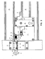
- the whole assembly of a latch with a handle lock for a section door in the embodiment depicted in Figure 1, comprises a base plate 10, intended to be fixed on the inner face of an element G2 ( Figure 2) of the section door, and an operative set mounted on an adjustable support member 20 intended to be fixed on the inner face of the same element G2 of the section door as well as to the upper immediately adjacent element G3.
- the adjustable support member 20 is shown as separate from the base plate 10, but both parts could also be embodied, at least in part, as a single piece.
- the base plate 10 may also be omitted when the various component parts are mounted directly and separately on the section door elements, however its presence allows ensuring without difficulties that the various component parts are mounted on the section door in correct mutual positions.
- the adjustable support member 20 intended to be fixed to the element G2 of the section door forms a bracket 21 and it terminates at the upper end with a hinge 22, whose movable part 23 is intended to be connected to the overlying element G3 of the section door.
- the bracket 21 is fixed, in this case in an adjustable position, the base portion 30 of a cylindrical seat 31, wherein there is seated the hollow pivot or axle 40 of a small running wheel 41.
- the small running wheel 41 may be solid with the hollow pivot 40 which, in this case, should be rotatable in the cylindrical seat 31 which acts as a bearing, or even, and preferably, the small running wheel 41 is rotatably mounted by means of a bearing on the hollow axle 40, which then may be operatively fixed within the cylindrical seat 31 and, if needed, may be adjustable in its longitudinal position.
- the latch 50 has in this embodiment a connection member 60 intended to be connected to a handle lock.
- said connection member 60 extends in a direction perpendicular to latch 50, in order to allow a displacement of axes between the latch 50 and the operating member through which the handle lock transmits the movement to latch 50. This allows to freely choose the position in which the handle lock is fixed to element G2 of the section door.
- the connection member 60 may not extend in a direction perpendicular to latch 50, and in certain cases it may also be omitted.
- the handle lock designated in its whole by number 70, is mounted on the base plate 10 (or even directly on element G2 of the section door) and it has an operating member 71 intended to be connected to the connection member 60, preferably through an adjustable joint 61 of the connection member 60.
- the handle lock 70 may, if needed, have a second operating member 72, opposite the operating member 71, in order to operate a second latch (not shown) acting at the opposite end of element G2 of the section door.
- the second operating member 72 may be present even if not required, when use is made of a commercial handle lock, not especially designed and manufactured for being applied on a section door.
- latch 50 does not require to be operated on a length larger than the normal operation length of any latch whatever.
- the handle lock 70 may be of any known kind, it may be commercial or, even when it is especially manufactured for the application of the invention, it does not require design, construction or maneuver features different from those of a common handle lock.
- the handle lock 70 may positively operate both the advancement and the retraction of latch 50.
- the handle lock 70 may positively operate both the advancement and the retraction of latch 50.
- the handle lock 70 may provide an automatic engagement of the latch, prearranged at a preceding time by the handle lock.
- connection member 60 is slidably mounted with respect to the proximal end portion of latch 50, and between this connection member 60 and a stop 52 carried by the latch there is inserted a compression spring 80.
- Stop 52 may be formed by an elastic ring inserted in a groove of latch 50.
- an elastic ring 53 limits the stroke of the connection member 60 by avoiding its escape from the proximal end of latch 50.
- the handle lock can prearrange the latch closure in any moment, when the latch is not in correspondence with the engagement opening of the guide bar, and the closure order for the latch, emitted by the handle lock, is transformed by spring 80 in an elastic stress applied to latch 50, whose distal end portion 51 is thus elastically pushed against the corresponding guide bar.
- the end portion 51 slides therefore against the web of the guide bar during the displacement of the section door and, when the section door attains its closure position, it finds itself in front of the corresponding engagement opening and it elastically springs therein, thus blocking the section door in its closure position.
- this end portion may preferably be rounded as it has been represented.
- This first set may be supplied to the manufacturers of section doors, being intended to cooperate with a handle lock of any kind and of any different provenance.
- This first set can also be deprived of a hinge, when it is preferred to use a hinge separate therefrom.
- the adjustable base 30 which carries the cylindrical seat 31, the hollow pivot or axle 40 with a small running wheel 41, and the latch 50 extending in the cavity of the hollow pivot or axle 40, form a second set which may be supplied to the manufacturers of section doors, being intended to be applied on the bracket 21 of a support member 20 with hinge 22, of a known type and possibly of a different provenance, or even on a support member separate from the hinge.
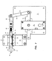
- the lock 70 is of the same type shown in Figures 1 and 2, but the connection between a connection member 63 of the latch 50 and the operating member 72 of lock 70 is done by means of a two-beams lever 90, which is pivoted at 91 to the base plate 10.
- This arrangement also allows, when needed, to mutually proportion the operative strokes of latch 50 and of the operating member 72 of lock 70, by suitably choosing the ratio between the two beams of lever 90.
- a lock 77 of the same kind used according to Figure 9 may be oriented in such a way, that its operating member 78 displaces in the same direction of latch 50, namely horizontal according to the drawing.
- the operating member 78 of lock 77 may be directly connected to the connection member 63 of latch 50.
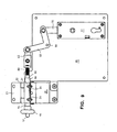
- FIG 11 there is represented a particular application of a lock as that according to Figure 9, inserted in an lock device intended to operate a set according to the invention.
- This lock device is enclosed in a box 99, which is represented deprived of a cover plate which, in use, covers the mechanisms.
- Lock 77 has an operating member 78 which displaces along the longitudinal direction of lock 77, namely in vertical direction according to the drawing. With this operating member 78 is slidingly coupled a rod 88, which projects at top with a portion 89 from the box 99 and carries a pivot 98. To this pivot 98 are articulated angular two-beams levers 83 pivoted at 84 to box 99. These levers have the same transmission function of the angular two-beam 93 according to Figure 9. They are connected to the connection member 63 of latch by means of a flexible metallic cable 82. There is shown also a second cable 82 which is intended to operate another latch (not represented) located at the opposite side of the section door.
- the portion 89 of rod 88 may be connected by means of a cable (not represented) to a motor mechanism in such a way that the latches are displaced in their open position when the motor mechanism has to open the section door, without requiring that the user opens beforehand the lock 77.
- Figure 11 also shows that, in those cases in which an adjustment of the position of latch 50 is not required, the bracket portion 21 of the support member 20 according to Figure 1 can be omitted, and this support member may be reduced to a plate, directly supporting a partially cylindrical seat 31 wherein the hollow axle 40 of the small wheel 41 is seated, and to which the hinge portion 23 is articulated. In this way a reduction of the cost of the device is obtained.
- Figure 12 shows as the latch 50 may be arranged for its manual operation, by providing the same with a handle 55 or other manual maneuver means. Even in this case it is possible to provide the automatic closure of the latch, by inserting a spring 80 between a shoulder 54 of latch 50 and a squared stop 34 of the adjustable support member 30.
Landscapes
- Engineering & Computer Science (AREA)
- Mechanical Engineering (AREA)
- Lock And Its Accessories (AREA)
- Gates (AREA)
- Wing Frames And Configurations (AREA)
- Power-Operated Mechanisms For Wings (AREA)
Claims (16)
- Un ensemble comprenant un verrou (50) et une roulette (41), destiné à la fermeture d'une porte sectionnelle constituée par nombre d'éléments (E) allongés en horizontale et connectés l'un l'autre par des charnières (C), formant un store roulant qui glisse le long de guides latérales (G), dans lequel, en proximité des charnières (C) situées entre les éléments (E) du store sont prévues, à chaque extrémité des éléments (E) du store, des roulettes (R) tournant sur des pivots ou essieux et se déplaçant le long des guides latérales (G), chaque guide latérale comprenant une branche verticale (G1) définissant la position opérationnelle de la porte sectionnelle quand elle est fermée, une branche supérieure horizontale (G2) définissant une position de disparition de la porte sectionnelle quand elle est ouverte, et une branche courbe de connexion (G3) reliant lesdites branches verticale et horizontale, le verrou (50), quand il est monté, se trouvant de côté sur la porte sectionnelle, pouvant être déplacé entre une position inactive et une position active, et étant disposé pour engager, dans sa position active, une ouverture prévue dans une des guides latérales (G), dans lequel ledit verrou (50) est disposé coaxial à ladite roulette (41) de l'ensemble, la roulette (41) étant destinée à se déplacer dans la guide latérale (G) de la porte sectionnelle, caractérisé en ce que la roulette (41) est montée sur un pivot ou essieu creux (40) de l'ensemble, que le verrou (50) est guidé à se déplacer dans la cavité dudit pivot ou essieu creux (40), et que l'ensemble comprend aussi un organe de support (20) sur lequel est monté ledit pivot ou essieu creux (40) qui porte la roulette (41) et dans la cavité duquel est guidé et se déplace le verrou (50), ledit organe de support (20) comportant des moyens pour le monter, le cas échéant dans une position réglable, sur un élément (E) de la porte sectionnelle ou sur une de ses charnières (C).
- Un ensemble suivant la revendication 1, caractérisé en ce que ledit organe de support (20) comporte un siège (31) partiellement cylindrique, dans lequel est monté ledit pivot ou essieu creux (40).
- Un ensemble suivant la revendication 1 ou 2, caractérisé en ce qu'il comporte aussi une charnière (22-23) destinée à être fixée à deux éléments (E) adjacents de la porte sectionnelle.
- Un ensemble suivant la revendication 2, caractérisé en ce que des moyens (30) de réglage de la position sont interposés entre ledit organe de support (20) et ledit siège cylindrique (31).
- Un ensemble suivant la revendication 3 ou 4, caractérisé en ce que ledit organe de support (20) comporte une console (21).
- Un ensemble suivant la revendication 3 ou 4, caractérisé en ce que ledit organe de support (20) a substantiellement la forme d'une plaque.
- Un ensemble suivant la revendication 1, caractérisé en ce que le verrou (50) est pourvu d'un moyen (55) pour sa commande manuelle.
- Un ensemble suivant la revendication 1, caractérisé en ce que le verrou (50) est pourvu d'un organe de connexion (60; 63) destiné à être connecté à une serrure à poignée (70; 74; 77) pour l'actionnement du verrou (50).
- Un ensemble suivant la revendication 8, caractérisé en ce que ledit organe de connexion (60) s'étend en direction perpendiculaire au verrou (50) pour permettre un désaxement entre le verrou (50) et un organe par lequel la serrure (70) transmet l'actionnement au verrou (70).
- Un ensemble suivant une quelconque des revendications précédentes, caractérisé en ce que le verrou (50) est pourvu d'un ressort (80) disposé pour transmettre au verrou (50), d'une façon élastiquement souple, une force dirigée vers la position de fermeture, de sorte à permettre une fermeture automatique du verrou (50) quand la porte sectionnelle atteint sa position de fermeture.
- Un ensemble suivant la revendication 8, caractérisé en ce qu'il comporte en outre une serrure à poignée (70; 74; 77) reliée audit organe de connexion (60; 63).
- Un ensemble suivant la revendication 11, caractérisé en ce que l'organe opérationnel (75) de la serrure à poignée (74) est directement relié à l'organe de connexion (63) du verrou.
- Un ensemble suivant la revendication 11, caractérisé en ce que l'organe opérationnel (72; 78) de la serrure à poignée (70; 77) est relié à l'organe de connexion (63) du verrou (50) per un levier (90; 93) à deux bras, lequel peut éventuellement être angulaire.
- Un ensemble suivant les revendications 11 et 10, caractérisé en ce que l'organe opérationnel (78) de la serrure à poignée (77) est relié à l'organe de connexion (63) du verrou (50) par un câble métallique flexible (82).
- Un ensemble suivant la revendication 10, caractérisé en ce que, pour faciliter le déplacement de la portion d'extrémité distale (51) du verrou (50) contre le fond du guide (G), ladite portion d'extrémité (51) est arrondie ou bien elle est pourvue d'une roulette ou balle disposée pour rouler contre le fond du guide.
- Un ensemble suivant une quelconque des revendications précédentes, caractérisé en ce que l'ensemble comporte un dispositif de serrure (99) comprenant une serrure à poignée (77), un organe opérationnel (78), une tringle (88) reliée à coulisse audit organe opérationnel (78), au moins un levier angulaire à deux bras (83) articulé à ladite tringle (88) et relié au verrou (50), et des moyens (78,98) prévus pour transmettre à ladite tringle (88) les déplacements dudit organe opérationnel (78) dans une direction seulement, ladite tringle (88) étant éventuellement utilisée pour actionner le verrou .(50) à partir d'un mécanisme à moteur.
Applications Claiming Priority (2)
| Application Number | Priority Date | Filing Date | Title |
|---|---|---|---|
| ITTO20020830 | 2002-09-24 | ||
| ITTO20020830 ITTO20020830A1 (it) | 2002-09-24 | 2002-09-24 | Chiavistello per porte sezionali e simili, ed insiemi operativi includenti tale chiavistello. |
Publications (2)
| Publication Number | Publication Date |
|---|---|
| EP1403452A1 EP1403452A1 (fr) | 2004-03-31 |
| EP1403452B1 true EP1403452B1 (fr) | 2006-11-29 |
Family
ID=31972233
Family Applications (1)
| Application Number | Title | Priority Date | Filing Date |
|---|---|---|---|
| EP20030077919 Expired - Lifetime EP1403452B1 (fr) | 2002-09-24 | 2003-09-16 | Ensemble de verrou pour portes sectionnelles |
Country Status (8)
| Country | Link |
|---|---|
| US (1) | US7011347B2 (fr) |
| EP (1) | EP1403452B1 (fr) |
| AT (1) | ATE347005T1 (fr) |
| CA (1) | CA2440269C (fr) |
| DE (1) | DE60310000T2 (fr) |
| ES (1) | ES2277024T3 (fr) |
| IT (1) | ITTO20020830A1 (fr) |
| PT (1) | PT1403452E (fr) |
Families Citing this family (22)
| Publication number | Priority date | Publication date | Assignee | Title |
|---|---|---|---|---|
| DE102004062995B4 (de) * | 2004-12-22 | 2007-01-18 | Dorma Gmbh + Co. Kg | Handentriegelungseinheit für eine Schiebetür |
| US20070056694A1 (en) * | 2005-08-24 | 2007-03-15 | Mullet Willis J | Wind resistant movable barrier |
| DE102006012213A1 (de) * | 2006-03-16 | 2007-09-20 | Hörmann KG Brockhagen | Sektionaltor (I) |
| US7861762B2 (en) * | 2007-08-16 | 2011-01-04 | 4Front Engineered Solutions, Inc. | Overhead doors and associated track, guide, and bracket assemblies for use with same |
| WO2009033236A1 (fr) * | 2007-09-13 | 2009-03-19 | Kingspan Holdings (Irl) Limited | Charnière pour porte à sections |
| US8468746B2 (en) * | 2008-09-30 | 2013-06-25 | Tyto Life LLC | Sealing systems for garage door |
| US9187931B2 (en) * | 2011-09-01 | 2015-11-17 | Jamas Enterprises LLC | Sliding pin lock mechanism for overhead door |
| US9303683B1 (en) * | 2012-05-26 | 2016-04-05 | Leonard Ray Newcomb, Jr. | Detachable connector system for multi-panel structure |
| FR2994130B1 (fr) * | 2012-07-31 | 2015-07-17 | Jean Chereau Sas | Dispositif de fermeture d'un compartiment d'un vehicule de transport de marchandises |
| US8893764B2 (en) | 2012-08-08 | 2014-11-25 | 4Front Engineered Solutions, Inc. | Overhead door decelerators and associated devices, systems, and methods |
| US9926955B1 (en) * | 2014-08-08 | 2018-03-27 | Taylor & Lego Holdings, LLC | Latch |
| US10370871B2 (en) * | 2015-09-08 | 2019-08-06 | Dl Manufacturing | Overhead door lock |
| US10876339B2 (en) * | 2015-11-19 | 2020-12-29 | 218, Llc | Overhead garage door system with sealing feature |
| KR102615111B1 (ko) * | 2016-06-13 | 2023-12-20 | 구글 엘엘씨 | 인간 운영자로의 에스컬레이션 |
| CN108073236A (zh) * | 2016-11-11 | 2018-05-25 | 鸿富锦精密工业(武汉)有限公司 | 锁定装置 |
| US10808425B2 (en) * | 2017-02-20 | 2020-10-20 | Cornellcookson, Llc | Spring loaded lock bolt |
| JP7093645B2 (ja) * | 2018-02-16 | 2022-06-30 | 株式会社オカムラ | 収納什器 |
| CA3115344A1 (fr) * | 2018-09-28 | 2020-04-02 | Cw Products Pty Ltd | Ensemble de verrouillage de volet roulant |
| CN110984717B (zh) * | 2019-12-11 | 2025-05-06 | 西屋月台屏蔽门(广州)有限公司 | 一种轨道交通站台门的滑动门手动解锁机构 |
| CN110952840B (zh) * | 2019-12-31 | 2020-12-25 | 常州瓦良格电气有限公司 | 一种屏蔽门用机械式电磁锁 |
| ES2797554B2 (es) * | 2020-06-07 | 2021-07-06 | Cortes Jose Antonio Gonzalez | Mecanismo de accionamiento de manillas de apertura de puertas, mediante presión de pedal |
| US12264523B2 (en) | 2020-11-30 | 2025-04-01 | Daryl W. Bruckelmyer | Overhead garage door system with sealing feature |
Family Cites Families (36)
| Publication number | Priority date | Publication date | Assignee | Title |
|---|---|---|---|---|
| US1880850A (en) * | 1928-03-21 | 1932-10-04 | Owen L Dautrick | Garage doorlock |
| US1949805A (en) * | 1930-05-06 | 1934-03-06 | Oscar C Mcgary | Sliding door trackway |
| US1804329A (en) * | 1930-12-31 | 1931-05-05 | Carrie Horner | Door |
| US1858804A (en) * | 1931-01-12 | 1932-05-17 | Evold H Carlson | Door-securing mechanism |
| US2039296A (en) * | 1931-03-16 | 1936-05-05 | Howard D Colman | Sliding door |
| US2048377A (en) * | 1934-02-01 | 1936-07-21 | Stanley Works | Overhead door lock |
| US2124969A (en) * | 1936-03-25 | 1938-07-26 | Huck Gerhardt Company Inc | Overhead garage door construction |
| US2124970A (en) * | 1936-03-25 | 1938-07-26 | Huck Gerhardt Company Inc | Closing and locking device for overhead garage doors |
| US2375837A (en) * | 1944-03-06 | 1945-05-15 | Phenix Mfg Company Inc | Overhead door guiding mechanism |
| US2580584A (en) * | 1948-01-06 | 1952-01-01 | R & E Engineering Company | Garage door locking mechanism |
| US3000203A (en) | 1959-01-20 | 1961-09-19 | Crawford Door Co | Lock mechanism |
| US3159205A (en) * | 1961-10-10 | 1964-12-01 | Varacalli James | Garage door sealing device |
| US3177022A (en) * | 1963-05-07 | 1965-04-06 | Mckee Door Company | Latching mechanism for overhead doors |
| US3163033A (en) * | 1963-08-30 | 1964-12-29 | Overhead Door Corp | Lock and latch means for upwardly acting doors and the like |
| US3543441A (en) * | 1969-02-20 | 1970-12-01 | Gordon La Porte | Vertically slidable door |
| US3683652A (en) | 1970-10-05 | 1972-08-15 | Holmes Hardware & Sales Co | Center lock inside handle keeper |
| US3788678A (en) * | 1972-09-25 | 1974-01-29 | H Switzgable | Adjustable garage door lock |
| US4080757A (en) | 1976-09-20 | 1978-03-28 | Floyd Westerman | Door latch |
| US4119133A (en) * | 1977-06-06 | 1978-10-10 | Dwight Carter | Insulated garage door |
| DE3248498A1 (de) | 1982-12-29 | 1984-07-05 | Rollwände- & Jalousienfabrik C. Behrens GmbH & Co, 3000 Hannover | Vorrichtung zum arretieren von sektionalverschluessen |
| DE8529024U1 (de) | 1985-10-11 | 1987-02-12 | Hörmann KG Amshausen, 4803 Steinhagen | Zusatz-Verschluß für ein Garagentor |
| US4739584A (en) * | 1986-10-23 | 1988-04-26 | Peter Zellman | Garage door locking mechanism |
| US6463988B1 (en) * | 1988-05-19 | 2002-10-15 | Wayne-Dalton Corp. | Wind-resistant sectional overhead door |
| US4880046A (en) * | 1988-09-26 | 1989-11-14 | Jerry Gesy | Door sealing apparatus |
| US5001861A (en) * | 1989-08-17 | 1991-03-26 | Hahn Richard E | Automatic universal deadbolt locking device |
| RU2107798C1 (ru) * | 1991-03-27 | 1998-03-27 | Ярмо Шехольм | Система с передвижным элементом |
| US5489130A (en) * | 1994-01-18 | 1996-02-06 | Clark; Ronald L. | Overhead door lock |
| US5522446A (en) * | 1994-06-15 | 1996-06-04 | Wayne-Dalton Corp. | Sectional overhead door |
| DK173184B1 (da) | 1996-09-02 | 2000-03-06 | Ark | Hejseport |
| US6006560A (en) * | 1997-10-27 | 1999-12-28 | Winnebago Industries, Inc. | Latch mechanism for a door |
| US6485068B1 (en) * | 1997-12-12 | 2002-11-26 | Sauve Raymond | Fall arrestor and lockdown device for vertical lift doors |
| KR20010042403A (ko) * | 1998-04-02 | 2001-05-25 | 스티븐 제이. 켈리 | 다지점 래치용 로드 롤러 시스템 |
| US6112799A (en) * | 1998-05-19 | 2000-09-05 | Wayne-Dalton Corp. | Wind-resistant sectional overhead door |
| EP1041230A3 (fr) | 1999-03-31 | 2003-01-29 | Hörmann Kg Amshausen | Serrure de porte, notamment pour porte basculante |
| US6141913A (en) * | 1999-06-08 | 2000-11-07 | Marvin Lumber And Cedar Company | Window sash position maintainer |
| US6431615B1 (en) * | 2000-04-28 | 2002-08-13 | Fisher Hamilton L.L.C. | Latching assembly |
-
2002
- 2002-09-24 IT ITTO20020830 patent/ITTO20020830A1/it unknown
-
2003
- 2003-09-09 CA CA 2440269 patent/CA2440269C/fr not_active Expired - Fee Related
- 2003-09-10 US US10/658,534 patent/US7011347B2/en not_active Expired - Fee Related
- 2003-09-16 EP EP20030077919 patent/EP1403452B1/fr not_active Expired - Lifetime
- 2003-09-16 AT AT03077919T patent/ATE347005T1/de not_active IP Right Cessation
- 2003-09-16 DE DE2003610000 patent/DE60310000T2/de not_active Expired - Lifetime
- 2003-09-16 PT PT03077919T patent/PT1403452E/pt unknown
- 2003-09-16 ES ES03077919T patent/ES2277024T3/es not_active Expired - Lifetime
Also Published As
| Publication number | Publication date |
|---|---|
| PT1403452E (pt) | 2007-03-30 |
| EP1403452A1 (fr) | 2004-03-31 |
| US20050017516A1 (en) | 2005-01-27 |
| CA2440269C (fr) | 2009-01-06 |
| ATE347005T1 (de) | 2006-12-15 |
| ITTO20020830A1 (it) | 2004-03-25 |
| CA2440269A1 (fr) | 2004-03-24 |
| DE60310000D1 (de) | 2007-01-11 |
| ES2277024T3 (es) | 2007-07-01 |
| US7011347B2 (en) | 2006-03-14 |
| DE60310000T2 (de) | 2007-09-20 |
Similar Documents
| Publication | Publication Date | Title |
|---|---|---|
| EP1403452B1 (fr) | Ensemble de verrou pour portes sectionnelles | |
| US11643855B2 (en) | Door handle for vehicle | |
| RU2350731C2 (ru) | Открывающее и закрывающее устройство для поднимаемых раздвижных дверей и окон | |
| AU2006291528A1 (en) | Body for a motor vehicle | |
| US6877278B2 (en) | Door closing arrangement for controlling closure sequence of turnable double doors | |
| US20240209669A1 (en) | Hinge for a roof window and roof window with a set of hinges | |
| CA2162338A1 (fr) | Mecanisme de verrouillage pour fenetres, portes, etc. | |
| EP0051309A2 (fr) | Fenêtre | |
| CA2150924C (fr) | Porte coulissante, porte coulissante et louvoyante ou porte escamotable a un ou a deux battants | |
| US6250013B1 (en) | Device for opening and closing an opening in a wall | |
| DE19513809C1 (de) | Schalthebel für ein Automatikgetriebe in einem Kraftfahrzeug | |
| KR20240146659A (ko) | 창문 또는 문의 윙, 특히 슬라이딩 윙의 강제 이동을 위한 이동 장치 | |
| KR20250115312A (ko) | 창문 또는 문의 윙, 특히 슬라이딩 윙의 강제 이동을 위한 이동 장치 | |
| DE19516588C1 (de) | Feststellvorrichtung für Fenster, Türen od. dgl. | |
| EP2216494A2 (fr) | Dispositif d'ombrage de bâtiments doté de rails de guidage pouvant être sortis | |
| US4168594A (en) | Remote controller for hinged window | |
| EP3921499A1 (fr) | Dispositif d'entraînement pivotant d'un battant | |
| DE10343360A1 (de) | Ver- und Entriegelungsvorrichtung für Fahrzeugtüren, insbesondere Schwenkschiebetüren für Schienenfahrzeuge | |
| DE3026037A1 (de) | Fahrzeugschiebetuer | |
| US20060005352A1 (en) | Handle, in particular for motor car doors | |
| GB2387200A (en) | Driving mechanism having entraining device for sliding door | |
| DE2759372A1 (de) | Fahrzeugschwingtuer | |
| RU2263193C1 (ru) | Устройство для перемещения сдвижной двери | |
| EP1178174B1 (fr) | Ferrure pour fenêtres ou portes coulissantes ou analogues | |
| DE1957568C3 (de) | Getriebe für ein insbesondere mit einem Ganzglasflügel versehenes Fenster, Tür o.dgl |
Legal Events
| Date | Code | Title | Description |
|---|---|---|---|
| PUAI | Public reference made under article 153(3) epc to a published international application that has entered the european phase |
Free format text: ORIGINAL CODE: 0009012 |
|
| AK | Designated contracting states |
Kind code of ref document: A1 Designated state(s): AT BE BG CH CY CZ DE DK EE ES FI FR GB GR HU IE IT LI LU MC NL PT RO SE SI SK TR |
|
| AX | Request for extension of the european patent |
Extension state: AL LT LV MK |
|
| 17P | Request for examination filed |
Effective date: 20040910 |
|
| AKX | Designation fees paid |
Designated state(s): AT BE BG CH CY CZ DE DK EE ES FI FR GB GR HU IE IT LI LU MC NL PT RO SE SI SK TR |
|
| 17Q | First examination report despatched |
Effective date: 20050404 |
|
| RAP1 | Party data changed (applicant data changed or rights of an application transferred) |
Owner name: PREFER S.P.A. |
|
| RTI1 | Title (correction) |
Free format text: LATCH ASSEMBLY FOR SECTIONAL DOORS |
|
| GRAP | Despatch of communication of intention to grant a patent |
Free format text: ORIGINAL CODE: EPIDOSNIGR1 |
|
| GRAS | Grant fee paid |
Free format text: ORIGINAL CODE: EPIDOSNIGR3 |
|
| GRAA | (expected) grant |
Free format text: ORIGINAL CODE: 0009210 |
|
| RAP1 | Party data changed (applicant data changed or rights of an application transferred) |
Owner name: PREFER COMMERCIALE S.R.L. |
|
| AK | Designated contracting states |
Kind code of ref document: B1 Designated state(s): AT BE BG CH CY CZ DE DK EE ES FI FR GB GR HU IE IT LI LU MC NL PT RO SE SI SK TR |
|
| PG25 | Lapsed in a contracting state [announced via postgrant information from national office to epo] |
Ref country code: IT Free format text: LAPSE BECAUSE OF FAILURE TO SUBMIT A TRANSLATION OF THE DESCRIPTION OR TO PAY THE FEE WITHIN THE PRESCRIBED TIME-LIMIT;WARNING: LAPSES OF ITALIAN PATENTS WITH EFFECTIVE DATE BEFORE 2007 MAY HAVE OCCURRED AT ANY TIME BEFORE 2007. THE CORRECT EFFECTIVE DATE MAY BE DIFFERENT FROM THE ONE RECORDED. Effective date: 20061129 Ref country code: CZ Free format text: LAPSE BECAUSE OF FAILURE TO SUBMIT A TRANSLATION OF THE DESCRIPTION OR TO PAY THE FEE WITHIN THE PRESCRIBED TIME-LIMIT Effective date: 20061129 Ref country code: AT Free format text: LAPSE BECAUSE OF FAILURE TO SUBMIT A TRANSLATION OF THE DESCRIPTION OR TO PAY THE FEE WITHIN THE PRESCRIBED TIME-LIMIT Effective date: 20061129 Ref country code: RO Free format text: LAPSE BECAUSE OF FAILURE TO SUBMIT A TRANSLATION OF THE DESCRIPTION OR TO PAY THE FEE WITHIN THE PRESCRIBED TIME-LIMIT Effective date: 20061129 Ref country code: FI Free format text: LAPSE BECAUSE OF FAILURE TO SUBMIT A TRANSLATION OF THE DESCRIPTION OR TO PAY THE FEE WITHIN THE PRESCRIBED TIME-LIMIT Effective date: 20061129 Ref country code: BE Free format text: LAPSE BECAUSE OF FAILURE TO SUBMIT A TRANSLATION OF THE DESCRIPTION OR TO PAY THE FEE WITHIN THE PRESCRIBED TIME-LIMIT Effective date: 20061129 Ref country code: SI Free format text: LAPSE BECAUSE OF FAILURE TO SUBMIT A TRANSLATION OF THE DESCRIPTION OR TO PAY THE FEE WITHIN THE PRESCRIBED TIME-LIMIT Effective date: 20061129 Ref country code: LI Free format text: LAPSE BECAUSE OF FAILURE TO SUBMIT A TRANSLATION OF THE DESCRIPTION OR TO PAY THE FEE WITHIN THE PRESCRIBED TIME-LIMIT Effective date: 20061129 Ref country code: CH Free format text: LAPSE BECAUSE OF FAILURE TO SUBMIT A TRANSLATION OF THE DESCRIPTION OR TO PAY THE FEE WITHIN THE PRESCRIBED TIME-LIMIT Effective date: 20061129 Ref country code: SK Free format text: LAPSE BECAUSE OF FAILURE TO SUBMIT A TRANSLATION OF THE DESCRIPTION OR TO PAY THE FEE WITHIN THE PRESCRIBED TIME-LIMIT Effective date: 20061129 |
|
| REG | Reference to a national code |
Ref country code: GB Ref legal event code: FG4D |
|
| REG | Reference to a national code |
Ref country code: CH Ref legal event code: EP |
|
| REG | Reference to a national code |
Ref country code: IE Ref legal event code: FG4D |
|
| REF | Corresponds to: |
Ref document number: 60310000 Country of ref document: DE Date of ref document: 20070111 Kind code of ref document: P |
|
| PG25 | Lapsed in a contracting state [announced via postgrant information from national office to epo] |
Ref country code: DK Free format text: LAPSE BECAUSE OF FAILURE TO SUBMIT A TRANSLATION OF THE DESCRIPTION OR TO PAY THE FEE WITHIN THE PRESCRIBED TIME-LIMIT Effective date: 20070228 Ref country code: SE Free format text: LAPSE BECAUSE OF FAILURE TO SUBMIT A TRANSLATION OF THE DESCRIPTION OR TO PAY THE FEE WITHIN THE PRESCRIBED TIME-LIMIT Effective date: 20070228 Ref country code: BG Free format text: LAPSE BECAUSE OF FAILURE TO SUBMIT A TRANSLATION OF THE DESCRIPTION OR TO PAY THE FEE WITHIN THE PRESCRIBED TIME-LIMIT Effective date: 20070228 |
|
| REG | Reference to a national code |
Ref country code: PT Ref legal event code: SC4A Free format text: AVAILABILITY OF NATIONAL TRANSLATION Effective date: 20070227 |
|
| ET | Fr: translation filed | ||
| REG | Reference to a national code |
Ref country code: CH Ref legal event code: PL |
|
| REG | Reference to a national code |
Ref country code: ES Ref legal event code: FG2A Ref document number: 2277024 Country of ref document: ES Kind code of ref document: T3 |
|
| PLBE | No opposition filed within time limit |
Free format text: ORIGINAL CODE: 0009261 |
|
| STAA | Information on the status of an ep patent application or granted ep patent |
Free format text: STATUS: NO OPPOSITION FILED WITHIN TIME LIMIT |
|
| 26N | No opposition filed |
Effective date: 20070830 |
|
| PG25 | Lapsed in a contracting state [announced via postgrant information from national office to epo] |
Ref country code: MC Free format text: LAPSE BECAUSE OF NON-PAYMENT OF DUE FEES Effective date: 20070930 Ref country code: GR Free format text: LAPSE BECAUSE OF FAILURE TO SUBMIT A TRANSLATION OF THE DESCRIPTION OR TO PAY THE FEE WITHIN THE PRESCRIBED TIME-LIMIT Effective date: 20070301 |
|
| PG25 | Lapsed in a contracting state [announced via postgrant information from national office to epo] |
Ref country code: IE Free format text: LAPSE BECAUSE OF NON-PAYMENT OF DUE FEES Effective date: 20070917 |
|
| PG25 | Lapsed in a contracting state [announced via postgrant information from national office to epo] |
Ref country code: EE Free format text: LAPSE BECAUSE OF FAILURE TO SUBMIT A TRANSLATION OF THE DESCRIPTION OR TO PAY THE FEE WITHIN THE PRESCRIBED TIME-LIMIT Effective date: 20061129 |
|
| PG25 | Lapsed in a contracting state [announced via postgrant information from national office to epo] |
Ref country code: CY Free format text: LAPSE BECAUSE OF FAILURE TO SUBMIT A TRANSLATION OF THE DESCRIPTION OR TO PAY THE FEE WITHIN THE PRESCRIBED TIME-LIMIT Effective date: 20061129 Ref country code: LU Free format text: LAPSE BECAUSE OF NON-PAYMENT OF DUE FEES Effective date: 20070916 |
|
| PG25 | Lapsed in a contracting state [announced via postgrant information from national office to epo] |
Ref country code: TR Free format text: LAPSE BECAUSE OF FAILURE TO SUBMIT A TRANSLATION OF THE DESCRIPTION OR TO PAY THE FEE WITHIN THE PRESCRIBED TIME-LIMIT Effective date: 20061129 Ref country code: HU Free format text: LAPSE BECAUSE OF FAILURE TO SUBMIT A TRANSLATION OF THE DESCRIPTION OR TO PAY THE FEE WITHIN THE PRESCRIBED TIME-LIMIT Effective date: 20070530 |
|
| PGFP | Annual fee paid to national office [announced via postgrant information from national office to epo] |
Ref country code: ES Payment date: 20100920 Year of fee payment: 8 |
|
| PGFP | Annual fee paid to national office [announced via postgrant information from national office to epo] |
Ref country code: FR Payment date: 20101004 Year of fee payment: 8 |
|
| PGFP | Annual fee paid to national office [announced via postgrant information from national office to epo] |
Ref country code: GB Payment date: 20100901 Year of fee payment: 8 |
|
| PGFP | Annual fee paid to national office [announced via postgrant information from national office to epo] |
Ref country code: NL Payment date: 20100928 Year of fee payment: 8 Ref country code: PT Payment date: 20100831 Year of fee payment: 8 |
|
| PGFP | Annual fee paid to national office [announced via postgrant information from national office to epo] |
Ref country code: DE Payment date: 20101029 Year of fee payment: 8 |
|
| REG | Reference to a national code |
Ref country code: PT Ref legal event code: MM4A Free format text: LAPSE DUE TO NON-PAYMENT OF FEES Effective date: 20120316 |
|
| REG | Reference to a national code |
Ref country code: NL Ref legal event code: V1 Effective date: 20120401 |
|
| GBPC | Gb: european patent ceased through non-payment of renewal fee |
Effective date: 20110916 |
|
| PG25 | Lapsed in a contracting state [announced via postgrant information from national office to epo] |
Ref country code: PT Free format text: LAPSE BECAUSE OF NON-PAYMENT OF DUE FEES Effective date: 20120316 |
|
| REG | Reference to a national code |
Ref country code: FR Ref legal event code: ST Effective date: 20120531 |
|
| REG | Reference to a national code |
Ref country code: DE Ref legal event code: R119 Ref document number: 60310000 Country of ref document: DE Effective date: 20120403 |
|
| PG25 | Lapsed in a contracting state [announced via postgrant information from national office to epo] |
Ref country code: NL Free format text: LAPSE BECAUSE OF NON-PAYMENT OF DUE FEES Effective date: 20120401 Ref country code: DE Free format text: LAPSE BECAUSE OF NON-PAYMENT OF DUE FEES Effective date: 20120403 |
|
| PG25 | Lapsed in a contracting state [announced via postgrant information from national office to epo] |
Ref country code: FR Free format text: LAPSE BECAUSE OF NON-PAYMENT OF DUE FEES Effective date: 20110930 Ref country code: GB Free format text: LAPSE BECAUSE OF NON-PAYMENT OF DUE FEES Effective date: 20110916 |
|
| REG | Reference to a national code |
Ref country code: ES Ref legal event code: FD2A Effective date: 20130606 |
|
| PG25 | Lapsed in a contracting state [announced via postgrant information from national office to epo] |
Ref country code: ES Free format text: LAPSE BECAUSE OF NON-PAYMENT OF DUE FEES Effective date: 20110917 |