EP1403476B1 - Silencieux pour courant gazeux - Google Patents
Silencieux pour courant gazeux Download PDFInfo
- Publication number
- EP1403476B1 EP1403476B1 EP03020504A EP03020504A EP1403476B1 EP 1403476 B1 EP1403476 B1 EP 1403476B1 EP 03020504 A EP03020504 A EP 03020504A EP 03020504 A EP03020504 A EP 03020504A EP 1403476 B1 EP1403476 B1 EP 1403476B1
- Authority
- EP
- European Patent Office
- Prior art keywords
- flow
- passage
- chamber
- chambers
- gas
- Prior art date
- Legal status (The legal status is an assumption and is not a legal conclusion. Google has not performed a legal analysis and makes no representation as to the accuracy of the status listed.)
- Expired - Lifetime
Links
Images



Classifications
-
- F—MECHANICAL ENGINEERING; LIGHTING; HEATING; WEAPONS; BLASTING
- F01—MACHINES OR ENGINES IN GENERAL; ENGINE PLANTS IN GENERAL; STEAM ENGINES
- F01N—GAS-FLOW SILENCERS OR EXHAUST APPARATUS FOR MACHINES OR ENGINES IN GENERAL; GAS-FLOW SILENCERS OR EXHAUST APPARATUS FOR INTERNAL-COMBUSTION ENGINES
- F01N1/00—Silencing apparatus characterised by method of silencing
- F01N1/08—Silencing apparatus characterised by method of silencing by reducing exhaust energy by throttling or whirling
- F01N1/12—Silencing apparatus characterised by method of silencing by reducing exhaust energy by throttling or whirling using spirally or helically shaped channels
- F01N1/125—Silencing apparatus characterised by method of silencing by reducing exhaust energy by throttling or whirling using spirally or helically shaped channels in combination with sound-absorbing materials
-
- F—MECHANICAL ENGINEERING; LIGHTING; HEATING; WEAPONS; BLASTING
- F01—MACHINES OR ENGINES IN GENERAL; ENGINE PLANTS IN GENERAL; STEAM ENGINES
- F01N—GAS-FLOW SILENCERS OR EXHAUST APPARATUS FOR MACHINES OR ENGINES IN GENERAL; GAS-FLOW SILENCERS OR EXHAUST APPARATUS FOR INTERNAL-COMBUSTION ENGINES
- F01N1/00—Silencing apparatus characterised by method of silencing
- F01N1/02—Silencing apparatus characterised by method of silencing by using resonance
- F01N1/04—Silencing apparatus characterised by method of silencing by using resonance having sound-absorbing materials in resonance chambers
-
- F—MECHANICAL ENGINEERING; LIGHTING; HEATING; WEAPONS; BLASTING
- F01—MACHINES OR ENGINES IN GENERAL; ENGINE PLANTS IN GENERAL; STEAM ENGINES
- F01N—GAS-FLOW SILENCERS OR EXHAUST APPARATUS FOR MACHINES OR ENGINES IN GENERAL; GAS-FLOW SILENCERS OR EXHAUST APPARATUS FOR INTERNAL-COMBUSTION ENGINES
- F01N1/00—Silencing apparatus characterised by method of silencing
- F01N1/08—Silencing apparatus characterised by method of silencing by reducing exhaust energy by throttling or whirling
- F01N1/085—Silencing apparatus characterised by method of silencing by reducing exhaust energy by throttling or whirling throttling exhaust gas flow using a central core in a flow passage
-
- F—MECHANICAL ENGINEERING; LIGHTING; HEATING; WEAPONS; BLASTING
- F01—MACHINES OR ENGINES IN GENERAL; ENGINE PLANTS IN GENERAL; STEAM ENGINES
- F01N—GAS-FLOW SILENCERS OR EXHAUST APPARATUS FOR MACHINES OR ENGINES IN GENERAL; GAS-FLOW SILENCERS OR EXHAUST APPARATUS FOR INTERNAL-COMBUSTION ENGINES
- F01N1/00—Silencing apparatus characterised by method of silencing
- F01N1/08—Silencing apparatus characterised by method of silencing by reducing exhaust energy by throttling or whirling
- F01N1/089—Silencing apparatus characterised by method of silencing by reducing exhaust energy by throttling or whirling using two or more expansion chambers in series
-
- F—MECHANICAL ENGINEERING; LIGHTING; HEATING; WEAPONS; BLASTING
- F01—MACHINES OR ENGINES IN GENERAL; ENGINE PLANTS IN GENERAL; STEAM ENGINES
- F01N—GAS-FLOW SILENCERS OR EXHAUST APPARATUS FOR MACHINES OR ENGINES IN GENERAL; GAS-FLOW SILENCERS OR EXHAUST APPARATUS FOR INTERNAL-COMBUSTION ENGINES
- F01N1/00—Silencing apparatus characterised by method of silencing
- F01N1/08—Silencing apparatus characterised by method of silencing by reducing exhaust energy by throttling or whirling
- F01N1/10—Silencing apparatus characterised by method of silencing by reducing exhaust energy by throttling or whirling in combination with sound-absorbing materials
-
- F—MECHANICAL ENGINEERING; LIGHTING; HEATING; WEAPONS; BLASTING
- F01—MACHINES OR ENGINES IN GENERAL; ENGINE PLANTS IN GENERAL; STEAM ENGINES
- F01N—GAS-FLOW SILENCERS OR EXHAUST APPARATUS FOR MACHINES OR ENGINES IN GENERAL; GAS-FLOW SILENCERS OR EXHAUST APPARATUS FOR INTERNAL-COMBUSTION ENGINES
- F01N3/00—Exhaust or silencing apparatus having means for purifying, rendering innocuous, or otherwise treating exhaust
- F01N3/08—Exhaust or silencing apparatus having means for purifying, rendering innocuous, or otherwise treating exhaust for rendering innocuous
- F01N3/10—Exhaust or silencing apparatus having means for purifying, rendering innocuous, or otherwise treating exhaust for rendering innocuous by thermal or catalytic conversion of noxious components of exhaust
- F01N3/24—Exhaust or silencing apparatus having means for purifying, rendering innocuous, or otherwise treating exhaust for rendering innocuous by thermal or catalytic conversion of noxious components of exhaust characterised by constructional aspects of converting apparatus
- F01N3/28—Construction of catalytic reactors
- F01N3/2882—Catalytic reactors combined or associated with other devices, e.g. exhaust silencers or other exhaust purification devices
-
- F—MECHANICAL ENGINEERING; LIGHTING; HEATING; WEAPONS; BLASTING
- F01—MACHINES OR ENGINES IN GENERAL; ENGINE PLANTS IN GENERAL; STEAM ENGINES
- F01N—GAS-FLOW SILENCERS OR EXHAUST APPARATUS FOR MACHINES OR ENGINES IN GENERAL; GAS-FLOW SILENCERS OR EXHAUST APPARATUS FOR INTERNAL-COMBUSTION ENGINES
- F01N1/00—Silencing apparatus characterised by method of silencing
- F01N1/08—Silencing apparatus characterised by method of silencing by reducing exhaust energy by throttling or whirling
- F01N1/12—Silencing apparatus characterised by method of silencing by reducing exhaust energy by throttling or whirling using spirally or helically shaped channels
-
- F—MECHANICAL ENGINEERING; LIGHTING; HEATING; WEAPONS; BLASTING
- F01—MACHINES OR ENGINES IN GENERAL; ENGINE PLANTS IN GENERAL; STEAM ENGINES
- F01N—GAS-FLOW SILENCERS OR EXHAUST APPARATUS FOR MACHINES OR ENGINES IN GENERAL; GAS-FLOW SILENCERS OR EXHAUST APPARATUS FOR INTERNAL-COMBUSTION ENGINES
- F01N2210/00—Combination of methods of silencing
- F01N2210/04—Throttling-expansion and resonance
-
- F—MECHANICAL ENGINEERING; LIGHTING; HEATING; WEAPONS; BLASTING
- F01—MACHINES OR ENGINES IN GENERAL; ENGINE PLANTS IN GENERAL; STEAM ENGINES
- F01N—GAS-FLOW SILENCERS OR EXHAUST APPARATUS FOR MACHINES OR ENGINES IN GENERAL; GAS-FLOW SILENCERS OR EXHAUST APPARATUS FOR INTERNAL-COMBUSTION ENGINES
- F01N2230/00—Combination of silencers and other devices
- F01N2230/04—Catalytic converters
-
- F—MECHANICAL ENGINEERING; LIGHTING; HEATING; WEAPONS; BLASTING
- F01—MACHINES OR ENGINES IN GENERAL; ENGINE PLANTS IN GENERAL; STEAM ENGINES
- F01N—GAS-FLOW SILENCERS OR EXHAUST APPARATUS FOR MACHINES OR ENGINES IN GENERAL; GAS-FLOW SILENCERS OR EXHAUST APPARATUS FOR INTERNAL-COMBUSTION ENGINES
- F01N2470/00—Structure or shape of exhaust gas passages, pipes or tubes
- F01N2470/18—Structure or shape of exhaust gas passages, pipes or tubes the axis of inlet or outlet tubes being other than the longitudinal axis of apparatus
-
- F—MECHANICAL ENGINEERING; LIGHTING; HEATING; WEAPONS; BLASTING
- F01—MACHINES OR ENGINES IN GENERAL; ENGINE PLANTS IN GENERAL; STEAM ENGINES
- F01N—GAS-FLOW SILENCERS OR EXHAUST APPARATUS FOR MACHINES OR ENGINES IN GENERAL; GAS-FLOW SILENCERS OR EXHAUST APPARATUS FOR INTERNAL-COMBUSTION ENGINES
- F01N2470/00—Structure or shape of exhaust gas passages, pipes or tubes
- F01N2470/20—Dimensional characteristics of tubes, e.g. length, diameter
-
- F—MECHANICAL ENGINEERING; LIGHTING; HEATING; WEAPONS; BLASTING
- F01—MACHINES OR ENGINES IN GENERAL; ENGINE PLANTS IN GENERAL; STEAM ENGINES
- F01N—GAS-FLOW SILENCERS OR EXHAUST APPARATUS FOR MACHINES OR ENGINES IN GENERAL; GAS-FLOW SILENCERS OR EXHAUST APPARATUS FOR INTERNAL-COMBUSTION ENGINES
- F01N2470/00—Structure or shape of exhaust gas passages, pipes or tubes
- F01N2470/22—Inlet and outlet tubes being positioned on the same side of the apparatus
-
- F—MECHANICAL ENGINEERING; LIGHTING; HEATING; WEAPONS; BLASTING
- F01—MACHINES OR ENGINES IN GENERAL; ENGINE PLANTS IN GENERAL; STEAM ENGINES
- F01N—GAS-FLOW SILENCERS OR EXHAUST APPARATUS FOR MACHINES OR ENGINES IN GENERAL; GAS-FLOW SILENCERS OR EXHAUST APPARATUS FOR INTERNAL-COMBUSTION ENGINES
- F01N2490/00—Structure, disposition or shape of gas-chambers
- F01N2490/16—Chambers with particular shapes, e.g. spherical
-
- F—MECHANICAL ENGINEERING; LIGHTING; HEATING; WEAPONS; BLASTING
- F01—MACHINES OR ENGINES IN GENERAL; ENGINE PLANTS IN GENERAL; STEAM ENGINES
- F01N—GAS-FLOW SILENCERS OR EXHAUST APPARATUS FOR MACHINES OR ENGINES IN GENERAL; GAS-FLOW SILENCERS OR EXHAUST APPARATUS FOR INTERNAL-COMBUSTION ENGINES
- F01N2490/00—Structure, disposition or shape of gas-chambers
- F01N2490/18—Dimensional characteristics of gas chambers
-
- F—MECHANICAL ENGINEERING; LIGHTING; HEATING; WEAPONS; BLASTING
- F01—MACHINES OR ENGINES IN GENERAL; ENGINE PLANTS IN GENERAL; STEAM ENGINES
- F01N—GAS-FLOW SILENCERS OR EXHAUST APPARATUS FOR MACHINES OR ENGINES IN GENERAL; GAS-FLOW SILENCERS OR EXHAUST APPARATUS FOR INTERNAL-COMBUSTION ENGINES
- F01N3/00—Exhaust or silencing apparatus having means for purifying, rendering innocuous, or otherwise treating exhaust
- F01N3/08—Exhaust or silencing apparatus having means for purifying, rendering innocuous, or otherwise treating exhaust for rendering innocuous
- F01N3/10—Exhaust or silencing apparatus having means for purifying, rendering innocuous, or otherwise treating exhaust for rendering innocuous by thermal or catalytic conversion of noxious components of exhaust
- F01N3/24—Exhaust or silencing apparatus having means for purifying, rendering innocuous, or otherwise treating exhaust for rendering innocuous by thermal or catalytic conversion of noxious components of exhaust characterised by constructional aspects of converting apparatus
- F01N3/28—Construction of catalytic reactors
- F01N3/2882—Catalytic reactors combined or associated with other devices, e.g. exhaust silencers or other exhaust purification devices
- F01N3/2885—Catalytic reactors combined or associated with other devices, e.g. exhaust silencers or other exhaust purification devices with exhaust silencers in a single housing
-
- Y—GENERAL TAGGING OF NEW TECHNOLOGICAL DEVELOPMENTS; GENERAL TAGGING OF CROSS-SECTIONAL TECHNOLOGIES SPANNING OVER SEVERAL SECTIONS OF THE IPC; TECHNICAL SUBJECTS COVERED BY FORMER USPC CROSS-REFERENCE ART COLLECTIONS [XRACs] AND DIGESTS
- Y02—TECHNOLOGIES OR APPLICATIONS FOR MITIGATION OR ADAPTATION AGAINST CLIMATE CHANGE
- Y02A—TECHNOLOGIES FOR ADAPTATION TO CLIMATE CHANGE
- Y02A50/00—TECHNOLOGIES FOR ADAPTATION TO CLIMATE CHANGE in human health protection, e.g. against extreme weather
- Y02A50/20—Air quality improvement or preservation, e.g. vehicle emission control or emission reduction by using catalytic converters
Definitions
- the present invention relates to a device for silencing a gas flow therethrough.
- US 4,317,502 discloses a muffler for automobile internal combustion engines consisting of a housing having an inlet end where the exhaust gases are channelled through a tubular member having, a helical member so that the gases are forced into a spiral flow pattern.
- the helical member extends beyond the end of the tubular member so that the gases are then permitted to follow a larger spiral pattern where they reflect against the walls of the housing.
- the housing has an outlet opening which is smaller than the housing diameter which causes compression of the gases and further reflection and ' interference of the sound waves.
- the muffler is formed with a counter flow reverberation chamber, a central chamber and a directional-flow reverberation chamber.
- US 5,612,006 discloses an assembly combining a catalytic converter with a spiral muffler, particularly for small internal combustion engines.
- a catalytic converter In series are an expansion chamber, a venturi for air injection, a catalytic converter, and a phase-spreading spiral muffler.
- the muffler has a spirally coiled exhaust channel dead-ended at its inner extremity, with an outer extremity serving as a muffled exhaust outlet.
- a distribution chamber is adjacent the spiral exhaust channel, sharing a common wall therewith, and a plurality of streamlined slotted openings spaced along the exhaust channel at different distances from the muffled exhaust outlet introduce gas from the distribution chamber into the spiral channel.
- the construction includes a series-connected venturi and catalytic converter assembly mounted centrally and coaxially within a cylindrical expansion chamber, with elements of the muffler arranged coaxially around a projecting portion of the catalytic converter.
- An aspect of the invention relates to a device for silencing a gas flow directed therethrough and being adapted for installation in a flow system, said device comprising:
- a further aspect of the invention relates to a device for silencing a gas flow directed therethrough and being adapted for installation in a flow system, said device comprising:
- Sound absorptive material is preferably provided within at least one of the at least two acoustic chambers. Sound absorptive material may be provided within each of the at least two acoustic chambers.
- curvatures, preventing flow separation are preferably applied to at least part of the contour of the outlet and/or inlet of a pipe or passage of the device, said pipe or passage being the inlet pipe or its extension into the apparatus and/or the outlet pipe or its extension into the apparatus and/or a passage connecting two chambers.
- a device may comprise one or more radial diffusers and/or one or more axial diffusers and/or one or more circular conical diffusers and/or one or more annular diffusers and/or a plurality of conical diffusers arranged on a substantially cylindrical surface and/or one or more diffusers for reversing the direction of flow and/or one or more double diversion diffusers, at least some of the above-mentioned diffuser types being known per se from the cited prior art. Any other diffuser types known per se may be applied.
- the generatrix of at least part of at least one curved passage selected from said at least one passage may be wound in a peripheral direction, at least part of the curved passage having a plane spiral form.
- the generatrix of at least a part of at least one curved passage selected from said at least one passage may be wound in a peripheral direction, said part of said curved passage extending in a longitudinal direction, so as to form a screw-like helical form.
- the length of the passage may be significantly increased, the natural frequency of the silencing device thus being decreased.
- the flow of the passage may constitute a flow cross-sectional area increase in the flow direction.
- the cross-sectional area increase may be two-or three-dimensional.
- the passage may have any cross-sectional shape, such as rectangular, circular, ellipsoidal or any other shape.
- the curved part of the passage may extend radially over an angle less than 90°, or over an angle between 90° and 180°, or over an angle between 180° and 270°, or over an angle between 270° and 360°, or over an angle between 360° and 720°, or over an angle of 720° or more.
- the device according to the invention comprises at least two acoustic chambers, a first of which surrounds a second one, the second chamber thus being 'embedded' in the first one.
- the generatrix of the curved part of the passage may extend along a surface of revolution, so as to define itself a surface of revolution.
- the surface of revolution may have any shape, e.g., conical.
- At least one monolithic body or a monolith may be positioned upstream or downstream of an inlet passage and/or an outlet passage of the at least two chambers, in some embodiments the monolithic body may be positioned substantially immediately upstream or substantially immediately downstream of said inlet passage and/or said outlet passage of the at least two chambers.
- the monolithic body may be of an annular form.
- the term "monolithic body” or “monolith” designates, as is customary in the art, a body of an overall or macroscopic monolithic appearance, often a cylindrical body, which has a structure allowing an overall axial gas flow through the body.
- the term “monolithic” does not rule out that the body could be made from a plurality of segments joined or arranged together.
- the structure allowing an overall axial gas flow through the body will depend on the construction and material of the monolith; two typical relevant monolith types are:
- Monoliths are sometimes inserted into silencers so as to combine silencing with gas purification, either in catalytic processes, in mechanical filtering, or in both. In most cases such monoliths are placed within one or more chambers of the silencer. Monoliths can provide significant silencing at medium and high frequencies, but less silencing at low frequencies. Obviously, monoliths cause added pressure drop to the piping system.
- the monolith is usually made as a honeycomb structure with straight channels, termed a through-flow monolith.
- the walls are thin, so that the open frontal area is typically 70-90%, depending mainly on the material (ceramic, metal, etc.).
- a monolith may be made as a wall-flow monolith, i.e. the channels are perforated and partly blocked, so that the gas flow is forced to pass through those perforations, describing a tortuous pathway through the monolith.
- a monolith is used either for pure filtering or for combined filtering and catalytic treatment of the gas.
- the open frontal area becomes less than 70%.
- Wall-flow monoliths cause pressure drops which are substantially higher than pressure drops of through-flow monoliths.
- the device according to the invention is adapted for being mounted to a flow system, e.g., the exhaust system of a vehicle comprising an internal displacement engine and/or a turbo machine or it may be suited for being mounted to the exhaust system of a stationary power generating installation comprising an internal displacement engine and/or a turbo machine.
- vehicle may be any vehicle, such as e.g. a diesel engine powered truck, a bus, a car or a railway locomotive, a petrol, a gasoline or a gas engine powered truck, bus, car or any other moveable engine driven device.
- the vehicle may also be any ship or boat having a combustion device.
- the stationary power generating installation may be a power station having one or more gas turbines driven by flow originating from suitable combustion means, such as, e.g., one or more boilers, fuel engines or other combustion means.
- One major benefit of a device according to the invention is a significant reduction of pressure loss over the device compared to known devices.
- the reduction of pressure loss over the device reduces the fuel consumption of the combustion device and increases the power generated by the combustion device at a given fuel consumption.
- An appropriate location could be, e.g., the inlet pipe, the outlet pipe, a location upstream of the inlet pipe, a location downstream of the outlet pipe, or any appropriate position inside the device where the flow velocity corresponds to the gas flow rate origination from the combustion device.
- the invention provides a device for silencing a gas flow, the device having a substantially lower ⁇ -value.
- ⁇ will be lower than 10. Typically, it will be between 0.5 and 4.
- S1 shows an unattenuated noise source spectrum, e.g., after subjection to the so-called A-weighting
- S2 shows the spectrum of the attenuation caused by a silencer (which is to be subtracted from S1 to obtain the resulting attenuated spectrum).
- silencers are preferably designed in such a way that the lowest natural frequency, f e , for passages of the silencer, is lower than a characteristic frequency, f char , of the unattenuated noise source.
- f char is the frequency at which the A-weighted spectrum has its maximum P1, P2 being a secondary peak.
- A-weighting is commonly adopted to take into account the frequency-dependent sensitivity of the human ear.
- Most noise limit standards are based on dB(A).
- Fig. 2 illustrates how, as a first suggestion, the simple linear, i.e. non-weighted, unattenuated spectrum SL, can be used to more realistically assess the infrasound contribution having a maximum peak PL which is within the infrasound frequency range.
- A-weighting which suppresses infrasound
- the maximum peak is seen to shift from PA, which occurs in the audible frequency range, to the peak PL occurring at the lower (infrasound) frequency.
- some characteristic frequency can be established as an input for the designing and dimensioning procedure of the invention.
- the various measures of the present invention offer, also for infrasound attenuation, a better trade-off between the degree of attenuation, the pressure drop, and the space requirement for the silencer, as compared to conventional technique.
- SDB (dB) Total sound attenuation (damping) requirement.
- SDP (mm WG) Total pressure loss allowable through the silencer.
- f ign (Hz) Ignition frequency or firing frequency for the engine.
- ⁇ D (mm) Desired diameter of the outer casing
- ⁇ d (mm) Diameter of pipes corresponding to areas a (mm 2 ).
- Q (m 3 /s) Flow rate of exhaust gasses.
- c (m/s) Sound velocity.
- the passages between the chambers may be prolonged by several means either alone or in combination.
- the pipes may be prolonged backwards into the upstream chamber and forwards into the downstream chamber, or the pipes may be prolonged by adopting a helical design for same. If the pipes either alone or combined with a diffuser are prolonged both upstream and downstream, the outlet of the upstream pipe in a chamber may be downstream of the inlet of the downstream pipe, thereby twice reversing the direction of the main flow in said chamber.
- a diffuser having an umbrella-like shape with the convex surface thereof facing downstream will also have the effect of prolonging the passage and reversing the flow.
- baffle plates and guiding plates and bodies may be employed.
- Each diffuser may be a radial diffuser or an axial diffuser or a circular conical diffuser or an annular diffuser or a multiplicity of conical diffusers arranged on a cylindrical surface or a diffuser for reversing the direction of flow or a double diversion diffuser or any other kind of diffuser.
- All inlets of the passages should be suitably rounded so as to avoid vena contracta flow with associated vortices giving rise to pressure loss and noise that may be amplified in the passage by resonance.
- the outlets of the diffusers should, if possible, be located at the centre of the longitudinal direction of the chamber relative to the main flow direction and/or at the pressure node of a transverse oscillation in the chamber. Hereby, the basic resonance of the chamber in the two directions is repressed.
- any sound absorbing material in the silencer is important. Particularly in large silencers it should not be too thick or compact so as to not decrease the acoustic volume of the chambers.
- resonators are only used as supplements to achieve improved attenuation at and around selected frequencies which may need further attenuation after achieving otherwise good attenuation by adopting the series-type connection of acoustic filters according to the main principles of the invention.
- Fig. 4 shows a preferred embodiment of the invention in which a helical passage 12 connects two chambers 1 and 2, contained within a cylindrical casing 7 and separated by an inner, flat partition wall 8.
- the helical passage is delimited by casing 7, by an inner cylinder 42, and by helically formed sheets 60 and 61.
- Helical passage 12 is subdivided into a constant flow-area part 12b and a diffuser part 12c, in which the flow area gradually widens in the gas flow direction, as given by a gradually widening distance between sheets 60 and 61.
- Both chambers 1 and 2 are partly filled with sound absorption material Ba, contained behind perforated plates 41 and 43. These plates have been so formed and positioned that, together with the absorptive material, they help guiding the flow inside chambers 1 and 2 with low pressure drop and preventing unwanted flow swirling inside the chambers.
- Gas flow is led to the silencer via inlet pipe 6 and conical diffuser 10, which recovers dynamic pressure and helps further to prevent unwanted swirl inside chamber 1 by lowering the inlet flow velocity to the chamber.
- the flow generally turns 90 degrees before entering helical connecting passage 12 at 12a.
- a cylindrical rod 21 has been fitted onto inner cylinder 42 to improve inlet flow conditions, preventing vena contracta phenomena and inlet pressure losses.
- the flow first passes constant flow area part 12b and then diffuser part 12c in which dynamic pressure is recovered.
- the flow leaves passage 12 at outlet 12d, entering chamber 2.
- the general flow direction turns 90 degrees, both in plane AA and in plane CC, before entering outlet pipe 4.
- the length of the passage is approximately ⁇ times the casing diameter, contributing to a very low acoustical natural frequency f e , constituted by passage 12 and chambers 1 and 2.
- the length of casing 7 is only slightly in excess of the diameter.
- the flow-widening of the diffuser 12c can be achieved by varying the diameter of the inner cylinder 42.
- a helical passage can be fitted into a cubic casing, instead of a cylindrical casing.
- the wall 8, separating chamber 1 from chamber 2, can be a cylinder, and chamber 2 can be arranged essentially outside chamber 1, which is favourable from a shell noise emission point of view, since the sound level inside chamber 1 is higher than inside the downstream chamber 2.
- Fig. 5 shows an embodiment of the invention in which a monolith, e.g. a catalyser, is built into a two-chamber silencer with a helical passage connecting the two chambers.
- the first chamber 1 is a flat, cylinder-like volume at the top of the silencer.
- the second chamber is divided into two parts, 2a and 2b, the division being caused by annular monolith 100.
- Sound absorbing material, Ba is contained within a central cylinder 42, a perforated top sheet 41, and solid bottom plate 8.
- the helical passage 12 is delimited by the cylindrical silencer casing 7, by the top part of cylinder 42, and by two helical sheets 60 and 61.
- a catalytical monolith has rather thin walls, in which case it only to a very limited extent causes an acoustical subdivision of the second chamber of the silencer.
- sub-chamber 2a, sub-chamber 2b, and the gas part (the porosities) of monolith 100 together constitute a single silencer chamber from an acoustical point of view.
- This second chamber is separated from the first chamber by plate 8, by cylinder 42, and by the walls of helical passage 12, i.e. sound can only pass from chamber 1 to the second chamber via passage 12.
- a cylindrical rod, 21, has been fitted onto helical sheet 60 to prevent 'vena contracta' inlet flow.
- the flow rotates slightly more than 360 degrees around the silencer axis, simultaneously flowing a little downwards before leaving the passage at 12d, passing into chamber 2a.
- the flow is distributed around the annular inlet face to the monolith, at the same time changing its direction from tangential to axial flow, given by axial flow channels within the monolith.
- the axial flow changes back to tangential in chamber 2b, from which the flow leaves the silencer by pipe 4.
- silencers are required to be of a cylindrical design, since this form is rather easy to manufacture. But other forms may also be appropriate, e.g. elliptical, squared or conical forms.
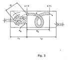
- a p is a chamber cross-section area, measured perpendicularly to the main flow trajectory in the chamber.
- D is.the straight line distance between the inlet to the chamber and the outlet from the chamber.
- s is a coordinate along the generatrix of a curved passage connecting two chambers.
- the passage length along the generatrix is L.
- D d is the direct straight line distance in space between passage inlet and outlet. Obviously, D d is shorter than L.
- L 1 and L 2 are the lengths of the first and second chambers, respectively.
- the cross-sectional area A of the chamber should be interpreted as the mean value along the mean trajectory for sound waves travelling from chamber inlet to chamber outlet. Usually, this trajectory more or less coincides with the flow trajectory.
- guide plates or similar devices can be fitted into chambers to stabilize the flow and help it to turn or deflect in an ordered way, preventing instability.
- Guide plates should not be of such a size or placed in such a way that they will cause acoustical isolation of certain chamber elements or division of a chamber into two or more sub-chambers.
- Flow-friendly, long passages can be created by subdividing the passage into two or more, parallel passages, each having smaller transverse dimensions.
- a circular pipe may be subdivided into several smaller-diameter pipes whose aggregate cross-sectional areas equal the cross-sectional area of the single, larger-diameter pipe.
- Smaller transverse dimensions allow for sharper turnings, since 'flow-friendliness' is very much related to the ratio between radius of curvature and transverse dimension.
- a helical passage form can also be applied to the tail pipe, i.e. the pipe leading exhaust gas from a silencer to the exterior environment, such as the atmosphere.
- a helical pipe can be wound around a cylindrical casing, ending up with a short straight end section of the tail pipe.
- the helical pipe may also be extended backwards, into the last chamber of the silencer, to provide a smooth outflow in the tangential direction.
- This configuration can be used to achieve a low natural frequency of the tail pipe - last chamber system, even when the exhaust to the exterior environment is prescribed to be positioned close to the silencer. This is a frequent situation in trucks and busses with silencers placed close to a front wheel and with sidewise exhaust from the vehicle.
Landscapes
- Engineering & Computer Science (AREA)
- Chemical & Material Sciences (AREA)
- Combustion & Propulsion (AREA)
- Mechanical Engineering (AREA)
- General Engineering & Computer Science (AREA)
- Chemical Kinetics & Catalysis (AREA)
- Health & Medical Sciences (AREA)
- Toxicology (AREA)
- Exhaust Silencers (AREA)
- Soundproofing, Sound Blocking, And Sound Damping (AREA)
- Gas Separation By Absorption (AREA)
- Glass Compositions (AREA)
- Compressor (AREA)
- Percussion Or Vibration Massage (AREA)
- Optical Fibers, Optical Fiber Cores, And Optical Fiber Bundles (AREA)
- Separation By Low-Temperature Treatments (AREA)
Claims (19)
- Dispositif d'amortissement du bruit d'un flux de gaz le traversant et adapté à l'installation sur un système d'écoulement, ledit dispositif comprenant :- un boîtier (7),- au moins deux chambres acoustiques (1, 2) contenues dans le boîtier (7), lesdites chambres (1, 2) étant traversées par le gaz,- au moins un tuyau d'entrée (6) pour amener le gaz dans l'une desdites au moins deux chambres acoustiques (1, 2),- au moins un passage (12) d'une longueur L et d'une surface de section transversale représentative a, destiné à amener le gaz de l'une des au moins deux chambres acoustiques à l'autre,- ledit dispositif présentant au moins deux transitions d'écoulement de la surface de section transversale pour le flux de gaz, lesdites au moins deux transitions d'écoulement étant présentes entre l'une des au moins deux chambres acoustiques et l'au moins un passage et entre l'au moins un passage et l'autre des au moins deux chambres acoustiques,- ledit gaz s'écoulant entre une surface de section transversale relativement inférieure ai et une surface de section transversale Ai relativement plus élevée, ai étant la surface de section transversale relativement inférieure du i-ième changement de surface de section transversale du flux de gaz et Ai étant la surface de section transversale relativement plus élevée à la i-ième transition de surface de section transversale du flux de gaz,caractérisé en ce que- ledit tuyau d'entrée (6) se poursuivant en un élément de déviation de l'écoulement, sous l'effet duquel le gaz s'écoule avec une composante radiale et destiné à provoquer un rendement en pression à l'écoulement en amont de la première desdites au moins deux chambres acoustiques (1, 2),ledit passage (12) comprenant au moins un diffuseur destiné à amener le flux de gaz dans la seconde (2) desdites au moins deux chambres acoustiques (1, 2), la partie du diffuseur (12c) dudit passage étant d'un type différent d'un diffuseur radial.
- Dispositif selon la revendication 1, dans lequel un ou plusieurs corps monolithiques (100) est compris dans chacune desdites au moins deux chambres acoustiques (1, 2).
- Dispositif selon la revendication 1 ou 2, dans lequel le matériau d'amortissement du bruit est fourni au sein d'au moins une des au moins deux chambres acoustiques.
- Dispositif selon l'une quelconque des revendications précédentes, dans lequel le matériau d'amortissement du bruit est fourni au sein de chacune des au moins deux chambres acoustiques.
- Dispositif selon l'une quelconque des revendications précédentes, dans lequel les courbures empêchant la séparation du flux sont appliquées à au moins une partie du contour d'au moins l'un des au moins un passage (12) et/ou au tuyau d'entrée (6).
- Dispositif selon l'une quelconque des revendications précédentes, comprenant un ou plusieurs diffuseurs axiaux et/ou un ou plusieurs diffuseurs coniques circulaires et/ou un ou plusieurs diffuseurs annulaires et/ou une multiplicité de diffuseurs coniques disposés sur une surface essentiellement cylindrique et/ou un ou plusieurs diffuseurs destinés à inverser le sens du flux et/ou un ou plusieurs diffuseurs à double dérivation.
- Dispositif selon la revendication 6, dans lequel chacune des au moins deux chambres acoustiques (1, 2) est essentiellement cylindrique et dans lequel une ou plusieurs sorties (12d) de ladite au moins une partie de diffuseur (12c) sont disposées essentiellement au niveau du centre axial de la chambre (1, 2) associée à ladite partie de diffuseurs (12c).
- Dispositif selon l'une quelconque des revendications précédentes, dans lequel chacune des au moins deux chambres acoustiques (1, 2) est essentiellement cylindrique, ladite chambre définissant ainsi un axe de cylindre et dans lequel une ou plusieurs sorties (12d) de ladite au moins une partie de diffuseur (12c) sont situées à un écart de l'axe de cylindre d'environ les deux tiers du rayon de la chambre acoustique (1, 2).
- Dispositif selon l'une quelconque des revendications précédentes, dans lequel au moins un passage (12) est annulaire, constitué d'un cylindre intérieur (42) et d'un cylindre extérieur.
- Dispositif selon la revendication 9, dans lequel au moins un des au moins un passages annulaires relie deux chambres (1, 2).
- Dispositif selon la revendication 9 ou 10, dans lequel l'au moins un passage annulaire constitue une augmentation de la surface de section transversale d'écoulement dans le sens d'écoulement.
- Dispositif selon l'une quelconque des revendications 9 à 11, dans lequel ledit passage annulaire (12) comprend une partie (12b) de zone à flux constant et une partie (12c) de diffuseurs de sortie.
- Dispositif selon l'une quelconque des revendications 9 à 11, dans lequel le matériau d'amortissement du bruit est compris dans ledit cylindre (42) et/ou au sein d'un cylindre de prolongement (41) rejoignant ladite première chambre (1) et/ou au sein d'un cylindre de prolongement (43) rejoignant ladite seconde chambre (2).
- Dispositif selon la revendication 13, dans lequel au moins une partie du cylindre de prolongement (41) est perforée.
- Dispositif selon l'une quelconque des revendications 9 à 13 dans lequel l'écart (D1) entre l'entrée (10a) de la première chambre (1) et l'entrée (12a) du passage annulaire (12) est si large qu'absolument aucun flux instable ne se produit dans la chambre (1).
- Dispositif selon la revendication 15, dans lequel le cylindre intérieur (43) présente une partie essentiellement non perforée, laquelle constitue au moins une partie du cylindre intérieur, constituant une paroi interne de la partie du diffuseur de sortie (12c).
- Dispositif selon l'une quelconque des revendications 15 et 16, dans lequel la partie essentiellement non perforée du cylindre intérieur (43) constitue au moins une partie d'une paroi interne de la chambre (2).
- Dispositif selon l'une quelconque des revendications précédentes, lesdites au moins deux chambres acoustiques présentant une entrée et une sortie, l'écart entre ladite entrée et ladite sortie, D, étant si large qu'absolument aucun flux instable ne se produit à l'intérieur de ladite chambre sélectionnée.
- Dispositif selon la revendication 18, dans lequel, aux fins d'empêcher un flux instable dans lesdites au moins deux chambres acoustiques, ledit écart D est 10 à 50 % plus grand que l'écart au niveau duquel un flux essentiellement instable se produirait.
Priority Applications (2)
| Application Number | Priority Date | Filing Date | Title |
|---|---|---|---|
| EP08101880A EP2182186B1 (fr) | 1996-09-30 | 1997-09-30 | Silencieux pour courant gazeux |
| DK08101880.6T DK2182186T3 (da) | 1996-09-30 | 1997-09-30 | Lyddæmper for gasstrøm |
Applications Claiming Priority (5)
| Application Number | Priority Date | Filing Date | Title |
|---|---|---|---|
| DK107096 | 1996-09-30 | ||
| DK107096 | 1996-09-30 | ||
| DK81697 | 1997-07-04 | ||
| DK81697 | 1997-07-04 | ||
| EP97941879A EP0934457B2 (fr) | 1996-09-30 | 1997-09-30 | Silencieux pour flux de gaz |
Related Parent Applications (3)
| Application Number | Title | Priority Date | Filing Date |
|---|---|---|---|
| EP97941879A Division-Into EP0934457B2 (fr) | 1996-09-30 | 1997-09-30 | Silencieux pour flux de gaz |
| EP97941879A Division EP0934457B2 (fr) | 1996-09-30 | 1997-09-30 | Silencieux pour flux de gaz |
| EP97941879.5 Division | 1998-04-09 |
Related Child Applications (1)
| Application Number | Title | Priority Date | Filing Date |
|---|---|---|---|
| EP08101880.6 Division-Into | 2008-02-22 |
Publications (3)
| Publication Number | Publication Date |
|---|---|
| EP1403476A2 EP1403476A2 (fr) | 2004-03-31 |
| EP1403476A3 EP1403476A3 (fr) | 2004-04-28 |
| EP1403476B1 true EP1403476B1 (fr) | 2010-06-16 |
Family
ID=26064713
Family Applications (3)
| Application Number | Title | Priority Date | Filing Date |
|---|---|---|---|
| EP08101880A Revoked EP2182186B1 (fr) | 1996-09-30 | 1997-09-30 | Silencieux pour courant gazeux |
| EP97941879A Expired - Lifetime EP0934457B2 (fr) | 1996-09-30 | 1997-09-30 | Silencieux pour flux de gaz |
| EP03020504A Expired - Lifetime EP1403476B1 (fr) | 1996-09-30 | 1997-09-30 | Silencieux pour courant gazeux |
Family Applications Before (2)
| Application Number | Title | Priority Date | Filing Date |
|---|---|---|---|
| EP08101880A Revoked EP2182186B1 (fr) | 1996-09-30 | 1997-09-30 | Silencieux pour courant gazeux |
| EP97941879A Expired - Lifetime EP0934457B2 (fr) | 1996-09-30 | 1997-09-30 | Silencieux pour flux de gaz |
Country Status (11)
| Country | Link |
|---|---|
| US (1) | US6332510B1 (fr) |
| EP (3) | EP2182186B1 (fr) |
| JP (1) | JP2001501269A (fr) |
| AT (3) | ATE265613T1 (fr) |
| AU (1) | AU730401B2 (fr) |
| BR (1) | BR9713244B1 (fr) |
| CA (1) | CA2267628C (fr) |
| DE (2) | DE69728891T3 (fr) |
| DK (2) | DK0934457T4 (fr) |
| ES (1) | ES2376496T3 (fr) |
| WO (1) | WO1998014693A1 (fr) |
Families Citing this family (20)
| Publication number | Priority date | Publication date | Assignee | Title |
|---|---|---|---|---|
| EP0918194A1 (fr) * | 1997-11-24 | 1999-05-26 | Abb Research Ltd. | Procédé et arrangement d'un système de brûleur et procédé et dispositif pour déterminer les propriétés d'un brûleur |
| CA2373774A1 (fr) * | 1998-03-30 | 1999-10-07 | Silentor Holding A/S | Silencieux et procede de mise en fonctionnement d'un vehicule |
| AU2001244090A1 (en) | 2000-03-21 | 2001-10-03 | Silentor Holding A/S | A silencer containing one or more porous bodies |
| US6457553B1 (en) * | 2000-08-04 | 2002-10-01 | Nelson Industries, Inc. | Low cost muffler |
| US6802690B2 (en) * | 2001-05-30 | 2004-10-12 | M & I Heat Transfer Products, Ltd. | Outlet silencer structures for turbine |
| FR2854427A1 (fr) * | 2003-04-29 | 2004-11-05 | Mig Production | Silencieux pour gaz d'echappement de moteurs a combustion interne. |
| US6935848B2 (en) * | 2003-05-19 | 2005-08-30 | Bristol Compressors, Inc. | Discharge muffler placement in a compressor |
| US20040234386A1 (en) * | 2003-05-19 | 2004-11-25 | Chumley Eugene Karl | Discharge muffler having an internal pressure relief valve |
| EP1507071B2 (fr) | 2003-08-11 | 2019-10-16 | Faurecia Emissions Control Technologies, Germany GmbH | Silencieux d'échappement |
| EP1781907B1 (fr) * | 2004-05-28 | 2009-07-29 | Silentor Holding A/S | Silencieux combine |
| JP4586513B2 (ja) * | 2004-11-29 | 2010-11-24 | 日産自動車株式会社 | 消音器構造 |
| US7584743B2 (en) | 2006-10-03 | 2009-09-08 | Deere & Company | Noise reduction for an internal combustion engine |
| US20110005856A1 (en) * | 2008-01-09 | 2011-01-13 | Leif Larson | Exhaust silencer |
| EP2110522A1 (fr) * | 2008-04-15 | 2009-10-21 | F. lli Bastelli snc di Bastelli Paolo, Bastelli Claudio & C. | Silencieux pour une suppression efficace du bruit d'échappement |
| US8938978B2 (en) | 2011-05-03 | 2015-01-27 | General Electric Company | Gas turbine engine combustor with lobed, three dimensional contouring |
| US9309842B2 (en) | 2013-02-07 | 2016-04-12 | General Electric Company | Air inlet silencer for turbomachines |
| CN103161555B (zh) * | 2013-03-21 | 2015-07-08 | 华电分布式能源工程技术有限公司 | 一种圆腔消声器的设计方法 |
| JP6381417B2 (ja) * | 2014-11-18 | 2018-08-29 | 愛知時計電機株式会社 | 消音器 |
| CN105569775B (zh) * | 2016-03-07 | 2018-06-19 | 广州汽车集团股份有限公司 | 排气消声器及具有其的车辆 |
| CN106932481B (zh) * | 2017-03-16 | 2023-06-16 | 中国东方电气集团有限公司 | 一种消音器消音特性测试系统 |
Family Cites Families (86)
| Publication number | Priority date | Publication date | Assignee | Title |
|---|---|---|---|---|
| DE189988C (fr) | ||||
| US1015698A (en) | 1911-07-17 | 1912-01-23 | Hiram Percy Maxim | Gas-engine silencer. |
| US1289856A (en) | 1917-12-18 | 1918-12-31 | Hiram Percy Maxim | Building-silencer. |
| US1510791A (en) | 1921-08-12 | 1924-10-07 | Leroy J Martel | Muffler for internal-combustion engines |
| US1695435A (en) | 1925-09-08 | 1928-12-18 | Maxim Silencer Co | Silencer |
| DE467515C (de) | 1926-04-24 | 1928-10-25 | Maxim Silencer Company | Schalldaempfer, insbesondere fuer Brennkraftmaschinen, bestehend in einem zylindrischen Gehaeuse mit spiralfoermigem Einsatz |
| DE469259C (de) | 1927-09-13 | 1928-12-07 | Herbert Terry & Sons Ltd | Auspufftopf fuer Brennkraftmaschinen, insbesondere an Kraftfahrzeugen |
| CH131187A (de) | 1928-01-18 | 1929-01-31 | Jean Lavanchy | Auspufftopf. |
| US1874326A (en) | 1929-06-14 | 1932-08-30 | Bell Telephone Labor Inc | Sound muffler |
| DE557140C (de) | 1929-08-14 | 1932-08-19 | Wilhelm Haegele | Schalldaempfer fuer Kraftfahrzeuge, bei welchen die Auspuffgase durch einen spiralfoermigen Kanal abgeleitet werden |
| DE570630C (de) | 1930-11-29 | 1933-02-22 | Johannes Bretschneider | Schalldaempfer fuer Brennkraftmaschinen mit spiralfoermiger Ableitung der Abgase |
| FR728003A (fr) | 1931-12-08 | 1932-06-28 | Silencieux pour moteurs à explosions | |
| GB408612A (en) † | 1932-10-11 | 1934-04-11 | Armstrong Whitworth Co Eng | Improvements in or relating to silencers for use on internal combustion engines |
| DE614930C (de) | 1933-05-04 | 1936-02-19 | Johannes Bretschneider | Schalldaempfer |
| DE634222C (de) | 1933-10-10 | 1936-08-21 | Joseph Laubacher | Schalldaempfer |
| NO56196C (fr) | 1933-11-21 | |||
| GB426769A (en) | 1933-11-29 | 1935-04-09 | Joseph Blanchard | Improvements in means for silencing gaseous currents |
| US2017748A (en) | 1934-04-30 | 1935-10-15 | Maxim Silencer Co | Sound attenuating device |
| DE736635C (de) | 1935-10-26 | 1943-06-23 | Erich Knopf Dr Ing | Vorrichtung zum Ableiten von Gasen sowie zum Schalldaempfen |
| GB495576A (en) | 1937-05-22 | 1938-11-16 | Fernand Jiles Joseph Servais | Improvements in and relating to silencers for gaseous currents |
| CH313645A (de) | 1952-12-22 | 1956-04-30 | Passerini Pietro | Schalldämpfungsvorrichtung für Explosionsmotoren |
| CH313447A (de) * | 1954-04-23 | 1956-04-15 | Resa Ag | Schalldämpfungseinrichtung an Explosionsmotoren |
| US2841235A (en) | 1955-04-04 | 1958-07-01 | Salvatore M Curioni | Sound muffler |
| GB829012A (en) | 1955-05-11 | 1960-02-24 | J R Andersson & Co A B | Improvements in or relating to fluid flow mufflers |
| US3018841A (en) | 1960-01-04 | 1962-01-30 | Gerlich Stephen | Muffler |
| US3114432A (en) * | 1961-08-21 | 1963-12-17 | Arvin Ind Inc | Sound attenuating gas conduit |
| FR1568944A (fr) | 1968-02-29 | 1969-05-30 | ||
| US3642095A (en) | 1968-03-22 | 1972-02-15 | Fujii Koygo Kk | Muffler |
| GB1358539A (en) | 1970-06-19 | 1974-07-03 | Cowl Ind Ltd | Silencing apparatus |
| US3897853A (en) | 1971-11-24 | 1975-08-05 | Silentor As | Silencer |
| DK128427B (da) | 1971-11-24 | 1974-04-29 | Silentor As | Lyddæmper. |
| DE2221970A1 (de) | 1972-05-05 | 1973-11-15 | Eberspaecher J | Anordnung zur katalytischen reinigung der abgase von verbrennungsmotoren |
| US3852042A (en) | 1973-01-29 | 1974-12-03 | Universal Oil Prod Co | Catalytic converter with exhaust gas modulating chamber for preventing damage to catalyst substrate |
| DE2307215A1 (de) | 1973-02-14 | 1974-08-22 | Volkswagenwerk Ag | Einrichtung zur katalytischen abgasreigigung |
| US3807527A (en) | 1973-03-14 | 1974-04-30 | Tenneco Inc | Pulse converter for exhaust system |
| FR2226865A5 (en) | 1973-04-17 | 1974-11-15 | Ferodo Sa | Exhaust silencer for automobile engines - has constant area gas passage to prevent back pressure on engine |
| CA1014028A (en) | 1974-01-24 | 1977-07-19 | Raymon E. Hunt | Muffler method and apparatus |
| DE2428964A1 (de) | 1974-06-15 | 1976-01-02 | Bosch Gmbh Robert | Abgasreaktor, insbesondere fuer brennkraftmaschinen |
| DE2429002A1 (de) | 1974-06-15 | 1976-01-08 | Bosch Gmbh Robert | Abgasreaktor |
| US4046219A (en) | 1975-03-20 | 1977-09-06 | Brunswick Corporation | Exhaust silencer apparatus for internal combustion engine |
| US4105089A (en) | 1975-11-24 | 1978-08-08 | Judd Frederick V H | Flow distributor for gas turbine silencers |
| DE2612421C3 (de) | 1976-03-24 | 1979-11-29 | Fa. J. Eberspaecher, 7300 Esslingen | Abgasschalldämpfer |
| US4094645A (en) | 1977-01-24 | 1978-06-13 | Uop Inc. | Combination muffler and catalytic converter having low backpressure |
| DE2715053A1 (de) | 1977-04-04 | 1978-10-12 | Eberspaecher J | Absorptions-schalldaempfer |
| US4209493A (en) | 1977-07-11 | 1980-06-24 | Nelson Industries, Inc. | Combination catalytic converter and muffler for an exhaust system |
| IT7853326U1 (it) | 1978-05-17 | 1979-11-17 | Fiat Spa | Silenziatore di scarico per automotrice ferroviarie |
| US4317502A (en) | 1979-10-22 | 1982-03-02 | Harris Theodore R | Engine exhaust muffler |
| DE3039742A1 (de) | 1980-10-22 | 1982-05-27 | Motoren-Werke Mannheim AG vorm. Benz Abt. stationärer Motorenbau, 6800 Mannheim | Abgas-waermeuebertrager, insbesondere fuer kleine verbrennungsmotoren mit abwaermeverwertung |
| PL135373B1 (en) | 1981-03-10 | 1985-10-31 | Inst Chemii Nieorganicznej | Piston-type silencer |
| GB8307371D0 (en) | 1983-03-17 | 1983-04-27 | Chillcotts Ltd | Exhaust silencer |
| IT1195502B (it) | 1983-06-02 | 1988-10-19 | Giuseppe Nieri | Dispositivo silenziatore particolarmente per gas di scarico e gas in genere in rapido movimento |
| US4485890A (en) | 1983-06-30 | 1984-12-04 | Harris Theodore R | Engine exhaust muffler |
| EP0158625A1 (fr) | 1984-03-15 | 1985-10-16 | Jenbacher Werke AG | Pot d'échappement catalytique pour moteurs à combustion interne |
| US4601363A (en) | 1984-11-06 | 1986-07-22 | Harris Theodore R | Large diesel engine exhaust muffler |
| EP0184060A1 (fr) | 1984-11-22 | 1986-06-11 | Tula Silencers (Proprietary) Limited | Silencieux d'échappement |
| US4601168A (en) | 1984-12-12 | 1986-07-22 | Harris Harold L | Noise and emission control apparatus |
| US4605092A (en) * | 1985-01-18 | 1986-08-12 | Harris Theodore R | Large, high r.p.m. diesel engine exhaust muffler |
| JPS61291714A (ja) | 1985-06-17 | 1986-12-22 | Jiyun Itani | ノイズコンバ−タ |
| DE3641942A1 (de) * | 1986-12-09 | 1988-06-23 | Leistritz Ag | Absorptions-abgasschalldaempfer |
| DE3733402A1 (de) | 1987-10-02 | 1989-04-13 | Emitec Emissionstechnologie | Katalysatoranordnung mit stroemungsleitkoerper |
| US5251123A (en) * | 1987-10-19 | 1993-10-05 | I C Operating, Inc. | High resolution system for sensing spatial coordinates |
| US5110560A (en) | 1987-11-23 | 1992-05-05 | United Technologies Corporation | Convoluted diffuser |
| US4848513A (en) | 1988-01-11 | 1989-07-18 | Ced's, Inc. | Noise abatement muffler |
| CA1262869A (fr) | 1988-06-23 | 1989-11-14 | Glen Knight | Echappement a combinaison de silencieux et convertisseur catalytique |
| US5016438A (en) | 1989-09-25 | 1991-05-21 | Harris International Sales Corporation | Emission control apparatus |
| US5227593A (en) * | 1990-09-12 | 1993-07-13 | Suzuki Kabushiki Kaisha | Muffler assembly for engine |
| DE4130113A1 (de) | 1990-09-22 | 1992-03-26 | Volkswagen Ag | Katalysatoranordnung mit einer eingangsseitigen diffusorartigen gasleitvorrichtung |
| US5220789A (en) | 1991-03-05 | 1993-06-22 | Ford Motor Company | Integral unitary manifold-muffler-catalyst device |
| US5184464A (en) | 1991-04-22 | 1993-02-09 | Harris International Sales Corporation | Noise and emmission control apparatus |
| FI921889A7 (fi) | 1991-05-02 | 1992-11-03 | Scambia Ind Dev Ag | Katalysator foer katalytisk behandling av avgaser |
| DE9314441U1 (de) | 1992-02-19 | 1994-01-13 | Leistritz AG & Co Abgastechnik, 90765 Fürth | Abgasschalldämpfer für Dieselmotoren insbesondere von Nutzfahrzeugen |
| EP0556846A1 (fr) | 1992-02-19 | 1993-08-25 | LEISTRITZ AG & CO. Abgastechnik | Silencieux d'échappement pour moteur diesel et en particulier pour véhicules utilitaires |
| DE69220245T2 (de) | 1992-04-15 | 1998-01-22 | Noise Cancellation Tech | Adaptiver mehrfrequenz-reaktiv-schalldämpfer |
| US5355973A (en) | 1992-06-02 | 1994-10-18 | Donaldson Company, Inc. | Muffler with catalytic converter arrangement; and method |
| US5426269A (en) | 1992-06-02 | 1995-06-20 | Donaldson Company, Inc. | Muffler with catalytic converter arrangement; and method |
| FI93138C (fi) | 1992-10-30 | 1995-02-27 | Eero Aitta | Keskipakoisvoimaa hiukkaspartikkelien erottelussa käyttävä katalyyttinen pakokaasupuhdistin dieselmoottoreita varten ja katalyyttinen pakokaasun puhdistusmenetelmä |
| DK169823B1 (da) | 1993-02-01 | 1995-03-06 | Silentor As | Lyddæmper |
| US5408828A (en) | 1993-12-10 | 1995-04-25 | General Motors Corporation | Integral cast diffuser for a catalytic converter |
| US5403557A (en) | 1994-04-19 | 1995-04-04 | Harris; Harold L. | Emission control apparatus for diesel engine |
| JPH0814033A (ja) | 1994-06-24 | 1996-01-16 | Caterpillar Inc | 内燃エンジン用モジュール触媒コンバータとマフラー |
| DK20095A (da) | 1995-02-24 | 1996-10-04 | Haldor Topsoe As | Fremgangsmåde til afmetallisering af residualolie |
| WO1996032572A1 (fr) † | 1995-04-11 | 1996-10-17 | Vølund Danstoker A/S | Echangeur de chaleur combine a un dispositif amortisseur de bruit |
| US6220021B1 (en) | 1995-05-19 | 2001-04-24 | Silentor Notox A/S | Silencer with incorporated catalyst |
| US5612006A (en) * | 1995-07-05 | 1997-03-18 | Fisk; James C. | Catalytic converter and phase-spreading spiral muffler assembly |
| FR2736966B1 (fr) * | 1995-07-17 | 1997-10-17 | Ferri Alain | Silencieux d'echappement pour moteur a explosion, pour aeronef |
| US5936210A (en) * | 1998-01-15 | 1999-08-10 | Maremont Exhaust Products, Inc. | High performance muffler |
-
1997
- 1997-09-30 AT AT97941879T patent/ATE265613T1/de not_active IP Right Cessation
- 1997-09-30 DK DK97941879.5T patent/DK0934457T4/da active
- 1997-09-30 AT AT08101880T patent/ATE533930T1/de active
- 1997-09-30 EP EP08101880A patent/EP2182186B1/fr not_active Revoked
- 1997-09-30 EP EP97941879A patent/EP0934457B2/fr not_active Expired - Lifetime
- 1997-09-30 AU AU43767/97A patent/AU730401B2/en not_active Ceased
- 1997-09-30 BR BRPI9713244-6A patent/BR9713244B1/pt not_active IP Right Cessation
- 1997-09-30 EP EP03020504A patent/EP1403476B1/fr not_active Expired - Lifetime
- 1997-09-30 US US09/147,883 patent/US6332510B1/en not_active Expired - Lifetime
- 1997-09-30 DE DE69728891T patent/DE69728891T3/de not_active Expired - Lifetime
- 1997-09-30 AT AT03020504T patent/ATE471438T1/de not_active IP Right Cessation
- 1997-09-30 CA CA002267628A patent/CA2267628C/fr not_active Expired - Fee Related
- 1997-09-30 WO PCT/DK1997/000417 patent/WO1998014693A1/fr not_active Ceased
- 1997-09-30 JP JP10516157A patent/JP2001501269A/ja active Pending
- 1997-09-30 ES ES08101880T patent/ES2376496T3/es not_active Expired - Lifetime
- 1997-09-30 DK DK08101880.6T patent/DK2182186T3/da active
- 1997-09-30 DE DE69739910T patent/DE69739910D1/de not_active Expired - Lifetime
Also Published As
| Publication number | Publication date |
|---|---|
| WO1998014693A9 (fr) | 1999-04-22 |
| EP0934457B1 (fr) | 2004-04-28 |
| EP0934457B2 (fr) | 2010-03-24 |
| EP2182186A2 (fr) | 2010-05-05 |
| ATE265613T1 (de) | 2004-05-15 |
| DK2182186T3 (da) | 2012-03-05 |
| ES2376496T3 (es) | 2012-03-14 |
| DE69728891D1 (de) | 2004-06-03 |
| US6332510B1 (en) | 2001-12-25 |
| DE69728891T2 (de) | 2005-04-28 |
| WO1998014693A1 (fr) | 1998-04-09 |
| EP2182186A3 (fr) | 2010-12-22 |
| BR9713244B1 (pt) | 2009-05-05 |
| EP1403476A2 (fr) | 2004-03-31 |
| AU4376797A (en) | 1998-04-24 |
| ATE533930T1 (de) | 2011-12-15 |
| JP2001501269A (ja) | 2001-01-30 |
| EP0934457A1 (fr) | 1999-08-11 |
| AU730401B2 (en) | 2001-03-08 |
| BR9713244A (pt) | 2000-01-18 |
| ATE471438T1 (de) | 2010-07-15 |
| DK0934457T3 (da) | 2004-08-09 |
| CA2267628C (fr) | 2007-05-15 |
| DK0934457T4 (da) | 2010-05-10 |
| DE69728891T3 (de) | 2010-09-09 |
| EP1403476A3 (fr) | 2004-04-28 |
| CA2267628A1 (fr) | 1998-04-09 |
| EP2182186B1 (fr) | 2011-11-16 |
| DE69739910D1 (de) | 2010-07-29 |
Similar Documents
| Publication | Publication Date | Title |
|---|---|---|
| EP0744536B1 (fr) | Silencieux | |
| US7549511B2 (en) | Exhaust sound and emission control systems | |
| EP2182186B1 (fr) | Silencieux pour courant gazeux | |
| EP1268989B1 (fr) | Silencieux contenant un ou plusieurs corps poreux | |
| US4368799A (en) | Straight-through flow muffler | |
| US6520286B1 (en) | Silencer and a method of operating a vehicle | |
| JP3231852B2 (ja) | 内燃機関の触媒コンバータに組み込まれたサイレンサ | |
| US20010015301A1 (en) | Self-tuning exhaust muffler | |
| RU2066376C1 (ru) | Трубопровод для выхлопных газов двигателя внутреннего сгорания | |
| US20090014238A1 (en) | Muffler | |
| CZ369598A3 (cs) | Zařízení pro tlumení a čištění výfukových plynů | |
| EP0127807A2 (fr) | Silencieux en particulier pour les gaz d'échappement, et en général pour les gaz à mouvement rapide | |
| EP1781907B1 (fr) | Silencieux combine | |
| US3994364A (en) | Mufflers | |
| JPH033914A (ja) | 内燃機関に用いる触媒作用を用する排気ガス浄化器とサイレンサー | |
| EP2047073A1 (fr) | Silencieux à fabrication facile | |
| EP1060328B1 (fr) | Silencieux | |
| EP1445453A2 (fr) | Silencieux et procédé de mise en fonctionnement d'un véhicule | |
| JP2005069191A (ja) | 排気装置 | |
| JPH0238005Y2 (fr) | ||
| JPH0223686B2 (fr) |
Legal Events
| Date | Code | Title | Description |
|---|---|---|---|
| PUAI | Public reference made under article 153(3) epc to a published international application that has entered the european phase |
Free format text: ORIGINAL CODE: 0009012 |
|
| PUAL | Search report despatched |
Free format text: ORIGINAL CODE: 0009013 |
|
| AC | Divisional application: reference to earlier application |
Ref document number: 0934457 Country of ref document: EP Kind code of ref document: P |
|
| AK | Designated contracting states |
Kind code of ref document: A2 Designated state(s): AT BE CH DE DK ES FI FR GB GR IE IT LI LU MC NL PT SE |
|
| AX | Request for extension of the european patent |
Extension state: AL LT LV RO SI |
|
| RIN1 | Information on inventor provided before grant (corrected) |
Inventor name: FREDERIKSEN, EYVIND Inventor name: FREDERIKSEN, SVEND |
|
| AK | Designated contracting states |
Kind code of ref document: A3 Designated state(s): AT BE CH DE DK ES FI FR GB GR IE IT LI LU MC NL PT SE |
|
| AX | Request for extension of the european patent |
Extension state: AL LT LV RO SI |
|
| AKX | Designation fees paid |
Designated state(s): AT BE CH DE DK ES FI FR GB GR IE IT LI LU MC NL PT SE |
|
| 17P | Request for examination filed |
Effective date: 20041028 |
|
| 17Q | First examination report despatched |
Effective date: 20050711 |
|
| 17Q | First examination report despatched |
Effective date: 20050711 |
|
| RAP1 | Party data changed (applicant data changed or rights of an application transferred) |
Owner name: SILENTOR HOLDING A/S |
|
| 17Q | First examination report despatched |
Effective date: 20050711 |
|
| GRAP | Despatch of communication of intention to grant a patent |
Free format text: ORIGINAL CODE: EPIDOSNIGR1 |
|
| 18D | Application deemed to be withdrawn |
Effective date: 20071103 |
|
| 18RA | Request filed for re-establishment of rights before grant |
Effective date: 20081003 |
|
| GRAS | Grant fee paid |
Free format text: ORIGINAL CODE: EPIDOSNIGR3 |
|
| D18D | Application deemed to be withdrawn (deleted) | ||
| GRAA | (expected) grant |
Free format text: ORIGINAL CODE: 0009210 |
|
| AC | Divisional application: reference to earlier application |
Ref document number: 0934457 Country of ref document: EP Kind code of ref document: P |
|
| AK | Designated contracting states |
Kind code of ref document: B1 Designated state(s): AT BE CH DE DK ES FI FR GB GR IE IT LI LU MC NL PT SE |
|
| REG | Reference to a national code |
Ref country code: CH Ref legal event code: EP |
|
| REG | Reference to a national code |
Ref country code: IE Ref legal event code: FG4D |
|
| REF | Corresponds to: |
Ref document number: 69739910 Country of ref document: DE Date of ref document: 20100729 Kind code of ref document: P |
|
| REG | Reference to a national code |
Ref country code: NL Ref legal event code: VDEP Effective date: 20100616 |
|
| PG25 | Lapsed in a contracting state [announced via postgrant information from national office to epo] |
Ref country code: SE Free format text: LAPSE BECAUSE OF FAILURE TO SUBMIT A TRANSLATION OF THE DESCRIPTION OR TO PAY THE FEE WITHIN THE PRESCRIBED TIME-LIMIT Effective date: 20100616 |
|
| PG25 | Lapsed in a contracting state [announced via postgrant information from national office to epo] |
Ref country code: AT Free format text: LAPSE BECAUSE OF FAILURE TO SUBMIT A TRANSLATION OF THE DESCRIPTION OR TO PAY THE FEE WITHIN THE PRESCRIBED TIME-LIMIT Effective date: 20100616 Ref country code: FI Free format text: LAPSE BECAUSE OF FAILURE TO SUBMIT A TRANSLATION OF THE DESCRIPTION OR TO PAY THE FEE WITHIN THE PRESCRIBED TIME-LIMIT Effective date: 20100616 |
|
| PG25 | Lapsed in a contracting state [announced via postgrant information from national office to epo] |
Ref country code: GR Free format text: LAPSE BECAUSE OF FAILURE TO SUBMIT A TRANSLATION OF THE DESCRIPTION OR TO PAY THE FEE WITHIN THE PRESCRIBED TIME-LIMIT Effective date: 20100917 |
|
| PG25 | Lapsed in a contracting state [announced via postgrant information from national office to epo] |
Ref country code: NL Free format text: LAPSE BECAUSE OF FAILURE TO SUBMIT A TRANSLATION OF THE DESCRIPTION OR TO PAY THE FEE WITHIN THE PRESCRIBED TIME-LIMIT Effective date: 20100616 |
|
| PG25 | Lapsed in a contracting state [announced via postgrant information from national office to epo] |
Ref country code: PT Free format text: LAPSE BECAUSE OF FAILURE TO SUBMIT A TRANSLATION OF THE DESCRIPTION OR TO PAY THE FEE WITHIN THE PRESCRIBED TIME-LIMIT Effective date: 20101018 Ref country code: BE Free format text: LAPSE BECAUSE OF FAILURE TO SUBMIT A TRANSLATION OF THE DESCRIPTION OR TO PAY THE FEE WITHIN THE PRESCRIBED TIME-LIMIT Effective date: 20100616 |
|
| PG25 | Lapsed in a contracting state [announced via postgrant information from national office to epo] |
Ref country code: IT Free format text: LAPSE BECAUSE OF FAILURE TO SUBMIT A TRANSLATION OF THE DESCRIPTION OR TO PAY THE FEE WITHIN THE PRESCRIBED TIME-LIMIT Effective date: 20100616 |
|
| PLBE | No opposition filed within time limit |
Free format text: ORIGINAL CODE: 0009261 |
|
| STAA | Information on the status of an ep patent application or granted ep patent |
Free format text: STATUS: NO OPPOSITION FILED WITHIN TIME LIMIT |
|
| PG25 | Lapsed in a contracting state [announced via postgrant information from national office to epo] |
Ref country code: DK Free format text: LAPSE BECAUSE OF FAILURE TO SUBMIT A TRANSLATION OF THE DESCRIPTION OR TO PAY THE FEE WITHIN THE PRESCRIBED TIME-LIMIT Effective date: 20100616 Ref country code: MC Free format text: LAPSE BECAUSE OF NON-PAYMENT OF DUE FEES Effective date: 20100930 |
|
| REG | Reference to a national code |
Ref country code: CH Ref legal event code: PL |
|
| 26N | No opposition filed |
Effective date: 20110317 |
|
| GBPC | Gb: european patent ceased through non-payment of renewal fee |
Effective date: 20100930 |
|
| REG | Reference to a national code |
Ref country code: FR Ref legal event code: ST Effective date: 20110531 |
|
| REG | Reference to a national code |
Ref country code: DE Ref legal event code: R097 Ref document number: 69739910 Country of ref document: DE Effective date: 20110316 |
|
| REG | Reference to a national code |
Ref country code: DE Ref legal event code: R119 Ref document number: 69739910 Country of ref document: DE Effective date: 20110401 |
|
| PG25 | Lapsed in a contracting state [announced via postgrant information from national office to epo] |
Ref country code: LI Free format text: LAPSE BECAUSE OF NON-PAYMENT OF DUE FEES Effective date: 20100930 Ref country code: CH Free format text: LAPSE BECAUSE OF NON-PAYMENT OF DUE FEES Effective date: 20100930 Ref country code: FR Free format text: LAPSE BECAUSE OF NON-PAYMENT OF DUE FEES Effective date: 20100930 Ref country code: DE Free format text: LAPSE BECAUSE OF NON-PAYMENT OF DUE FEES Effective date: 20110401 Ref country code: IE Free format text: LAPSE BECAUSE OF NON-PAYMENT OF DUE FEES Effective date: 20100930 |
|
| PG25 | Lapsed in a contracting state [announced via postgrant information from national office to epo] |
Ref country code: GB Free format text: LAPSE BECAUSE OF NON-PAYMENT OF DUE FEES Effective date: 20100930 |
|
| PG25 | Lapsed in a contracting state [announced via postgrant information from national office to epo] |
Ref country code: LU Free format text: LAPSE BECAUSE OF NON-PAYMENT OF DUE FEES Effective date: 20100930 |
|
| PG25 | Lapsed in a contracting state [announced via postgrant information from national office to epo] |
Ref country code: ES Free format text: LAPSE BECAUSE OF FAILURE TO SUBMIT A TRANSLATION OF THE DESCRIPTION OR TO PAY THE FEE WITHIN THE PRESCRIBED TIME-LIMIT Effective date: 20100927 |