EP1403486B1 - Séparateur de flux acoustique-structural pour compresseur à basse pression - Google Patents
Séparateur de flux acoustique-structural pour compresseur à basse pression Download PDFInfo
- Publication number
- EP1403486B1 EP1403486B1 EP03256079A EP03256079A EP1403486B1 EP 1403486 B1 EP1403486 B1 EP 1403486B1 EP 03256079 A EP03256079 A EP 03256079A EP 03256079 A EP03256079 A EP 03256079A EP 1403486 B1 EP1403486 B1 EP 1403486B1
- Authority
- EP
- European Patent Office
- Prior art keywords
- acoustic
- structural
- splitter
- lpc
- assembly
- Prior art date
- Legal status (The legal status is an assumption and is not a legal conclusion. Google has not performed a legal analysis and makes no representation as to the accuracy of the status listed.)
- Expired - Lifetime
Links
- 239000012814 acoustic material Substances 0.000 claims description 9
- 239000000463 material Substances 0.000 claims description 5
- 239000003351 stiffener Substances 0.000 claims description 5
- 239000002131 composite material Substances 0.000 claims description 4
- 238000010276 construction Methods 0.000 claims description 4
- 239000007769 metal material Substances 0.000 claims description 3
- 238000010586 diagram Methods 0.000 description 2
- 230000004048 modification Effects 0.000 description 2
- 238000012986 modification Methods 0.000 description 2
- 230000004075 alteration Effects 0.000 description 1
- 230000000712 assembly Effects 0.000 description 1
- 238000000429 assembly Methods 0.000 description 1
- 230000001010 compromised effect Effects 0.000 description 1
- 230000008602 contraction Effects 0.000 description 1
- 230000014759 maintenance of location Effects 0.000 description 1
- 230000003068 static effect Effects 0.000 description 1
Images


Classifications
-
- F—MECHANICAL ENGINEERING; LIGHTING; HEATING; WEAPONS; BLASTING
- F02—COMBUSTION ENGINES; HOT-GAS OR COMBUSTION-PRODUCT ENGINE PLANTS
- F02K—JET-PROPULSION PLANTS
- F02K3/00—Plants including a gas turbine driving a compressor or a ducted fan
- F02K3/02—Plants including a gas turbine driving a compressor or a ducted fan in which part of the working fluid by-passes the turbine and combustion chamber
- F02K3/04—Plants including a gas turbine driving a compressor or a ducted fan in which part of the working fluid by-passes the turbine and combustion chamber the plant including ducted fans, i.e. fans with high volume, low pressure outputs, for augmenting the jet thrust, e.g. of double-flow type
- F02K3/06—Plants including a gas turbine driving a compressor or a ducted fan in which part of the working fluid by-passes the turbine and combustion chamber the plant including ducted fans, i.e. fans with high volume, low pressure outputs, for augmenting the jet thrust, e.g. of double-flow type with front fan
-
- F—MECHANICAL ENGINEERING; LIGHTING; HEATING; WEAPONS; BLASTING
- F02—COMBUSTION ENGINES; HOT-GAS OR COMBUSTION-PRODUCT ENGINE PLANTS
- F02C—GAS-TURBINE PLANTS; AIR INTAKES FOR JET-PROPULSION PLANTS; CONTROLLING FUEL SUPPLY IN AIR-BREATHING JET-PROPULSION PLANTS
- F02C7/00—Features, components parts, details or accessories, not provided for in, or of interest apart form groups F02C1/00 - F02C6/00; Air intakes for jet-propulsion plants
- F02C7/04—Air intakes for gas-turbine plants or jet-propulsion plants
- F02C7/045—Air intakes for gas-turbine plants or jet-propulsion plants having provisions for noise suppression
-
- F—MECHANICAL ENGINEERING; LIGHTING; HEATING; WEAPONS; BLASTING
- F05—INDEXING SCHEMES RELATING TO ENGINES OR PUMPS IN VARIOUS SUBCLASSES OF CLASSES F01-F04
- F05D—INDEXING SCHEME FOR ASPECTS RELATING TO NON-POSITIVE-DISPLACEMENT MACHINES OR ENGINES, GAS-TURBINES OR JET-PROPULSION PLANTS
- F05D2250/00—Geometry
- F05D2250/50—Inlet or outlet
-
- F—MECHANICAL ENGINEERING; LIGHTING; HEATING; WEAPONS; BLASTING
- F05—INDEXING SCHEMES RELATING TO ENGINES OR PUMPS IN VARIOUS SUBCLASSES OF CLASSES F01-F04
- F05D—INDEXING SCHEME FOR ASPECTS RELATING TO NON-POSITIVE-DISPLACEMENT MACHINES OR ENGINES, GAS-TURBINES OR JET-PROPULSION PLANTS
- F05D2260/00—Function
- F05D2260/96—Preventing, counteracting or reducing vibration or noise
Definitions
- the present invention relates to an acoustic-structural low-pressure compressor (LPC) splitter assembly constructed so as to reduce weight and increase structural support. More specifically, the present invention relates to an acoustic-structural LPC splitter assembly that preferably provides integral support for a plurality of low-pressure compressor bleed exhaust ports.
- LPC low-pressure compressor
- a gas turbine splitter assembly is located axially downstream of the engine's fan stage.
- the fan exit stream air is "split" by the splitter assembly into two flow streams: core flow and bypass flow.
- a standard gas turbine splitter assembly consists of: the splitter nose, acoustic panel cowling, low-pressure compressor bleed exit duct, and low-pressure compressor (LPC) stator case support structure.
- This configuration consists of a large quantity of parts and is heavy, especially on large thrust engines.
- the low-pressure compressor bleed is used during engine starting and surge conditions.
- an object of the present invention in preferred embodiments at least to provide an acoustic-structural LPC splitter assembly providing integral support for a plurality of low-compressor bleed exhaust ports.
- an acoustic-structural low-pressure compressor (LPC) splitter assembly for use in an engine in combination with a fan exit guide vane (FEGV) interface and a splitter as claimed in claim 1.
- the acoustic-structural splitter assembly comprises a structural acoustic splitter through which are arranged a plurality of bleed exhaust ports.
- the present invention integrates several low-pressure compressor (LPC) static structure part functions into a single part while simultaneously reducing weight and cost and increasing acoustic treatment.
- the present invention combines the load bearing and hoop stiffness of the LPC bleed cavity structure with the acoustic treatment of the flowpath fairing.
- the resulting design is a sandwich construction of structural and acoustic materials providing the hoop and flexural stiffness and acoustic treatment needed in LPC fairings.
- FIG. 1 there is illustrated in cross section a conventional commercial LPC splitter assembly known in the art.
- the following described elements comprising the LPC splitter assembly are formed from rotating the cross section about a center axis 19 through 360 degrees.
- the flowpath fairing 1 with attached acoustic treatment bridges the expanse formed between the fairing front bolted joint 6 oriented towards the front of the engine and the fairing slip joint 5 located further aft of the fairing front bolted joint 6.
- Fairing slip joint 5 is supported in part by flowpath fairing support and stator case stiffener 3 which extends from the LPC inner case 17 to the fairing slip joint 5.
- An acoustic-structural LPC splitter assembly with the features of the preamble of claim 1 is disclosed in document US-A-5 222 360 .
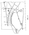
- FIG. 2 there is illustrated an acoustic-structural LPC splitter assembly according to the preferred embodiment of the present invention.
- the flowpath fairing is extended from splitter 22 to the fan exit guide vane (FEGV) interface 9, whereby there is formed fairing slip joint 21.
- FEGV fan exit guide vane
- flowpath fairing 1 becomes structural acoustic splitter 11.
- Structural acoustic splitter 11 is a load carrying member of full hoop construction. Structural acoustic splitter 11 is self supporting with regards to any attached acoustic treatment and provides support to the LPC inner case 17.
- the acoustic treatment is integral to structural acoustic splitter 11.
- structural acoustic splitter 11 may be formed of an acoustic material 53 with composite backing skin 51 bonded to one or both sides.
- the acoustic material 53 and/or the backing skin 51 may be comprised of metallic or composite material.
- the acoustic material 53 may be omitted entirely or sprayed or otherwise attached to an existing structural acoustic splitter 11.
- the structural acoustic splitter 11 improves LPC case concentricity, resulting in longer performance retention. Extending the flowpath fairing 1 to form structural acoustic splitter 11 also improves noise attenuation via an increase in acoustically treated surface area.
- low-pressure compressor bleed exhaust ports 2 are periodically cut through the structural acoustic splitter 11. By doing so, the metallic structure and bolts supporting these ports are eliminated. Low compressor bleed exhaust ports 2 may be glued in from the inner or outer diameter, bolted in, or otherwise fastened to structural acoustic splitter 11.
- the structural acoustic splitter 11 can still accommodate thermal growth along the engine axis by including an aft slip joint 21 at the FEGV interface 9. Positive circumferential, radial and axial restraint is still maintained by the conventional bolted joint 10.
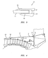
- Aft slip joint 21 is formed from full hoop slot 31 into which is inserted an end of structural acoustic splitter 11.
- a sacrificial wear material 33 Surrounding the end of structural acoustic splitter 11 and in contact with an inner surface 37 of full hoop slot 31 there is dispersed a sacrificial wear material 33.
- Sacrificial wear material 33 serves to prevent wear on structural acoustic splitter 11 and can be replaced when a quantity has been compromised sufficient to impede the performance of structural acoustic splitter 11.
- a lap seal 35 may be attached to structural acoustic splitter 11 and extend rearward to cover the interface between structural acoustic splitter 11 and full hoop slot 31.
- FIG. 4 there is illustrated an alternative embodiment of the present invention.
- a radial stiffener 41 is attached between the LPC inner case 17 and structural acoustic splitter 11. Radial stiffener 41 attaches to an underside of structural acoustic splitter 11 between aft slip joint 21 and bolted joint 10.
- the structural acoustic splitter 11 of the present invention weighs less than a standard splitter assembly due to reduced part count and a reduction in size of the LPC stator case support structure.
- the structural acoustic splitter 11 of the present invention is axially longer than a typical flowpath fairing 1 and provides a greater surface area for application of acoustic material, which will result in less fan noise.
- low-pressure low-compressor stage bleed exit ports radially flow core air into the bypass air stream and are positioned at discrete locations circumferentially around the cowl.
Landscapes
- Engineering & Computer Science (AREA)
- Chemical & Material Sciences (AREA)
- Combustion & Propulsion (AREA)
- Mechanical Engineering (AREA)
- General Engineering & Computer Science (AREA)
- Structures Of Non-Positive Displacement Pumps (AREA)
- Soundproofing, Sound Blocking, And Sound Damping (AREA)
- Details Of Audible-Bandwidth Transducers (AREA)
Claims (9)
- Ensemble d'aubage directeur de compresseur basse pression (LPC) acoustique structurel en combinaison avec une interface à pales de guidage de sortie de soufflante (FEGV) (9) et un aubage directeur (22) destiné à être utilisé dans un moteur, ledit ensemble d'aubage directeur de LPC acoustique structurel comprenant :un aubage directeur structurel acoustique (11), ledit aubage directeur structurel acoustique (11) ayant une première et une seconde extrémité, et une surface interne et externe ; etun joint coulissant (21) pour fixer ladite seconde extrémité dudit aubage directeur structurel acoustique (11) à l'interface FEGV (9) ;caractérisé en ce qu'il comprend en outre :un joint frontal (10) pour fixer ladite première extrémité dudit aubage directeur structurel acoustique (11) audit aubage directeur (22) ; et en ce queledit joint coulissant (21) comprend :une fente (31) ayant un premier et un second bord avant pour recevoir ladite seconde extrémité dudit aubage directeur structurel acoustique (11) ; etune matière sacrificielle (33) disposée autour d'une partie de ladite fente (31) en contact avec ladite seconde extrémité dudit aubage directeur structurel acoustique (11).
- Ensemble d'aubage directeur de LPC acoustique structurel selon la revendication 1, comprenant en outre une pluralité d'orifices de décharge (2) s'étendant à travers ledit aubage directeur structurel acoustique (11).
- Ensemble d'aubage directeur de LPC acoustique structurel selon la revendication 1 ou 2, dans lequel ladite fente (31) est construite sous forme de cercle complet.
- Ensemble d'aubage directeur de LPC acoustique structurel selon la revendication 1, 2 ou 3, dans lequel un joint de recouvrement (35) est fixé à ladite seconde extrémité dudit aubage directeur structurel acoustique (11) et s'étend pour couvrir ledit premier bord avant dudit joint coulissant (21).
- Ensemble d'aubage directeur de LPC acoustique structurel selon l'une quelconque des revendications précédentes, dans lequel ledit aubage directeur structurel acoustique (11) comprend :un matériau acoustique (53) ayant une première et une seconde surface ; etau moins une enveloppe dorsale structurelle (51) collée à ladite première ou seconde surface.
- Ensemble d'aubage directeur de LPC acoustique structurel selon la revendication 5, dans lequel ledit matériau acoustique (53) est un matériau métallique ou composite.
- Ensemble d'aubage directeur de LPC acoustique structurel selon la revendication 5 ou 6, dans lequel ladite enveloppe dorsale structurelle (51) est composée d'un matériau sélectionné dans le groupe consistant en matériaux métalliques et composites.
- Ensemble d'aubage directeur de LPC acoustique structurel selon l'une quelconque des revendications précédentes en combinaison en outre avec un carter interne de LPC (17), dans lequel ledit aubage directeur structurel acoustique (11) assure un support suffisant pour maintenir la concentricité du carter interne de LPC (17).
- Ensemble d'aubage directeur de LPC acoustique structurel selon l'une quelconque des revendications précédentes en combinaison en outre avec un carter interne de LPC (17), comprenant en outre un raidisseur radial (41) s'étendant radialement entre ledit aubage directeur structurel acoustique (11) et le carter interne de LPC (17).
Applications Claiming Priority (2)
| Application Number | Priority Date | Filing Date | Title |
|---|---|---|---|
| US261561 | 1994-06-17 | ||
| US10/261,561 US6766639B2 (en) | 2002-09-30 | 2002-09-30 | Acoustic-structural LPC splitter |
Publications (3)
| Publication Number | Publication Date |
|---|---|
| EP1403486A2 EP1403486A2 (fr) | 2004-03-31 |
| EP1403486A3 EP1403486A3 (fr) | 2004-11-24 |
| EP1403486B1 true EP1403486B1 (fr) | 2010-06-16 |
Family
ID=31977950
Family Applications (1)
| Application Number | Title | Priority Date | Filing Date |
|---|---|---|---|
| EP03256079A Expired - Lifetime EP1403486B1 (fr) | 2002-09-30 | 2003-09-26 | Séparateur de flux acoustique-structural pour compresseur à basse pression |
Country Status (4)
| Country | Link |
|---|---|
| US (1) | US6766639B2 (fr) |
| EP (1) | EP1403486B1 (fr) |
| JP (1) | JP3993153B2 (fr) |
| DE (1) | DE60332985D1 (fr) |
Families Citing this family (17)
| Publication number | Priority date | Publication date | Assignee | Title |
|---|---|---|---|---|
| US7249929B2 (en) * | 2003-11-13 | 2007-07-31 | United Technologies Corporation | Bleed housing |
| FR2872485B1 (fr) * | 2004-07-05 | 2006-09-15 | Snecma Moteurs Sa | Raidisseur pour compresseur basse pression d'un moteur d'aeronef |
| US7624581B2 (en) * | 2005-12-21 | 2009-12-01 | General Electric Company | Compact booster bleed turbofan |
| US7730715B2 (en) * | 2006-05-15 | 2010-06-08 | United Technologies Corporation | Fan frame |
| FR2902142B1 (fr) * | 2006-06-09 | 2008-09-05 | Snecma Sa | Systeme de decharge d'un compresseur a basse pression de turbomachine |
| US8262353B2 (en) * | 2007-11-30 | 2012-09-11 | General Electric Company | Decoupler system for rotor assemblies |
| EP2305960B1 (fr) * | 2009-09-28 | 2013-07-31 | Techspace Aero S.A. | Valve de purge dans le canal primaire du compresseur et procédé correspondant de suppression de phénomène de pompage |
| US8662831B2 (en) * | 2009-12-23 | 2014-03-04 | General Electric Company | Diaphragm shell structures for turbine engines |
| US20120070271A1 (en) * | 2010-09-21 | 2012-03-22 | Urban Justin R | Gas turbine engine with bleed duct for minimum reduction of bleed flow and minimum rejection of hail during hail ingestion events |
| US9140139B2 (en) | 2011-12-01 | 2015-09-22 | United Technologies Corporation | Structural joint for connecting a first component to a segmented second component |
| US20130192198A1 (en) * | 2012-01-31 | 2013-08-01 | Lisa I. Brilliant | Compressor flowpath |
| US8763753B2 (en) | 2012-02-10 | 2014-07-01 | General Electric Company | Acoustic panel and method of forming |
| US9546571B2 (en) | 2012-08-22 | 2017-01-17 | United Technologies Corporation | Mounting lug for connecting a vane to a turbine engine case |
| US9366185B2 (en) * | 2012-09-28 | 2016-06-14 | United Technologies Corporation | Flexible connection between a wall and a case of a turbine engine |
| US9534498B2 (en) | 2012-12-14 | 2017-01-03 | United Technologies Corporation | Overmolded vane platform |
| FR3005693B1 (fr) * | 2013-05-16 | 2017-12-22 | Snecma | Turbomachine d'aeronef a double flux comprenant une virole inter-veine a maintien aval simplifie |
| US10100843B2 (en) * | 2015-02-16 | 2018-10-16 | United Technologies Corporation | Gas turbine engine front center body architecture |
Family Cites Families (8)
| Publication number | Priority date | Publication date | Assignee | Title |
|---|---|---|---|---|
| US3477231A (en) * | 1967-12-26 | 1969-11-11 | Gen Electric | Noise reduction |
| US3542152A (en) * | 1968-04-08 | 1970-11-24 | Gen Electric | Sound suppression panel |
| US5307623A (en) * | 1991-05-28 | 1994-05-03 | General Electric Company | Apparatus and method for the diassembly of an ultra high bypass engine |
| US5222360A (en) * | 1991-10-30 | 1993-06-29 | General Electric Company | Apparatus for removably attaching a core frame to a vane frame with a stable mid ring |
| US5649419A (en) * | 1995-01-27 | 1997-07-22 | The Boeing Company | Rotating acoustically lined inlet splitter for a turbo-fan engine |
| US5782082A (en) * | 1996-06-13 | 1998-07-21 | The Boeing Company | Aircraft engine acoustic liner |
| US6182787B1 (en) * | 1999-01-12 | 2001-02-06 | General Electric Company | Rigid sandwich panel acoustic treatment |
| FR2831608B1 (fr) * | 2001-10-31 | 2004-01-02 | Snecma Moteurs | Dispositif de decharge dans un turbo reacteur a double flux |
-
2002
- 2002-09-30 US US10/261,561 patent/US6766639B2/en not_active Expired - Lifetime
-
2003
- 2003-09-26 EP EP03256079A patent/EP1403486B1/fr not_active Expired - Lifetime
- 2003-09-26 DE DE60332985T patent/DE60332985D1/de not_active Expired - Lifetime
- 2003-09-30 JP JP2003341551A patent/JP3993153B2/ja not_active Expired - Fee Related
Also Published As
| Publication number | Publication date |
|---|---|
| JP2004124943A (ja) | 2004-04-22 |
| DE60332985D1 (de) | 2010-07-29 |
| US6766639B2 (en) | 2004-07-27 |
| EP1403486A2 (fr) | 2004-03-31 |
| EP1403486A3 (fr) | 2004-11-24 |
| JP3993153B2 (ja) | 2007-10-17 |
| US20040060280A1 (en) | 2004-04-01 |
Similar Documents
| Publication | Publication Date | Title |
|---|---|---|
| US6766639B2 (en) | Acoustic-structural LPC splitter | |
| EP0834003B1 (fr) | Ensemble de confinement pour aubes de soufflante | |
| US6382905B1 (en) | Fan casing liner support | |
| EP3093240B1 (fr) | Entrée de nacelle présentant une extension de cylindre externe | |
| US8202041B2 (en) | Fan case for turbofan engine | |
| EP1083300B1 (fr) | Carter de soufflante avec structure de rétention à double paroi | |
| EP0816640B1 (fr) | Anneaux de rétention pour carter de turbomachine | |
| EP1852595B2 (fr) | Inverseur de poussée pour moteurs d'avion | |
| US8826669B2 (en) | Gas turbine exhaust case | |
| EP3447306B1 (fr) | Boîtier de confinement de soufflante pour moteur à turbine à gaz | |
| EP1095213B1 (fr) | Rotor de compresseur a basse pression et a soufflante integree, destine a un moteur a turbine a gaz | |
| EP3358174B1 (fr) | Ensemble d'échappement de turbine composite à matrice céramique pour moteur de turbine à gaz | |
| EP1857639A2 (fr) | Chassis de soufflante | |
| US4722184A (en) | Annular stator structure for a rotary machine | |
| EP2952696B1 (fr) | Ensemble turboréacteur à double flux avec cartouche de revêtement pour le carter de soufflante | |
| JP2008163950A (ja) | 案内ベーン及びそれを製作する方法 | |
| JPH0670378B2 (ja) | 遷移ダクトシ−ル構造体 | |
| US11084600B2 (en) | Nacelle inlet with reinforcement structure | |
| US20210054762A1 (en) | Gas turbine engine fan bumper | |
| EP4015777A1 (fr) | Installation de carénage de conduit de dérivation | |
| EP3760843B1 (fr) | Ensemble de conduits pour moteur de turbine à gaz | |
| EP3632791B1 (fr) | Entrée de nacelle à structure renforcée |
Legal Events
| Date | Code | Title | Description |
|---|---|---|---|
| PUAI | Public reference made under article 153(3) epc to a published international application that has entered the european phase |
Free format text: ORIGINAL CODE: 0009012 |
|
| AK | Designated contracting states |
Kind code of ref document: A2 Designated state(s): AT BE BG CH CY CZ DE DK EE ES FI FR GB GR HU IE IT LI LU MC NL PT RO SE SI SK TR |
|
| AX | Request for extension of the european patent |
Extension state: AL LT LV MK |
|
| PUAL | Search report despatched |
Free format text: ORIGINAL CODE: 0009013 |
|
| AK | Designated contracting states |
Kind code of ref document: A3 Designated state(s): AT BE BG CH CY CZ DE DK EE ES FI FR GB GR HU IE IT LI LU MC NL PT RO SE SI SK TR |
|
| AX | Request for extension of the european patent |
Extension state: AL LT LV MK |
|
| 17P | Request for examination filed |
Effective date: 20050105 |
|
| AKX | Designation fees paid |
Designated state(s): DE FR GB |
|
| 17Q | First examination report despatched |
Effective date: 20051103 |
|
| GRAP | Despatch of communication of intention to grant a patent |
Free format text: ORIGINAL CODE: EPIDOSNIGR1 |
|
| GRAS | Grant fee paid |
Free format text: ORIGINAL CODE: EPIDOSNIGR3 |
|
| GRAA | (expected) grant |
Free format text: ORIGINAL CODE: 0009210 |
|
| AK | Designated contracting states |
Kind code of ref document: B1 Designated state(s): DE FR GB |
|
| REF | Corresponds to: |
Ref document number: 60332985 Country of ref document: DE Date of ref document: 20100729 Kind code of ref document: P |
|
| PLBE | No opposition filed within time limit |
Free format text: ORIGINAL CODE: 0009261 |
|
| STAA | Information on the status of an ep patent application or granted ep patent |
Free format text: STATUS: NO OPPOSITION FILED WITHIN TIME LIMIT |
|
| 26N | No opposition filed |
Effective date: 20110317 |
|
| REG | Reference to a national code |
Ref country code: FR Ref legal event code: ST Effective date: 20110531 |
|
| REG | Reference to a national code |
Ref country code: DE Ref legal event code: R097 Ref document number: 60332985 Country of ref document: DE Effective date: 20110316 |
|
| PG25 | Lapsed in a contracting state [announced via postgrant information from national office to epo] |
Ref country code: FR Free format text: LAPSE BECAUSE OF NON-PAYMENT OF DUE FEES Effective date: 20100930 |
|
| REG | Reference to a national code |
Ref country code: DE Ref legal event code: R082 Ref document number: 60332985 Country of ref document: DE Representative=s name: SCHMITT-NILSON SCHRAUD WAIBEL WOHLFROM PATENTA, DE |
|
| REG | Reference to a national code |
Ref country code: DE Ref legal event code: R082 Ref document number: 60332985 Country of ref document: DE Representative=s name: SCHMITT-NILSON SCHRAUD WAIBEL WOHLFROM PATENTA, DE Ref country code: DE Ref legal event code: R081 Ref document number: 60332985 Country of ref document: DE Owner name: UNITED TECHNOLOGIES CORP. (N.D.GES.D. STAATES , US Free format text: FORMER OWNER: UNITED TECHNOLOGIES CORP., HARTFORD, CONN., US |
|
| PGFP | Annual fee paid to national office [announced via postgrant information from national office to epo] |
Ref country code: DE Payment date: 20190820 Year of fee payment: 17 |
|
| PGFP | Annual fee paid to national office [announced via postgrant information from national office to epo] |
Ref country code: GB Payment date: 20190820 Year of fee payment: 17 |
|
| REG | Reference to a national code |
Ref country code: DE Ref legal event code: R119 Ref document number: 60332985 Country of ref document: DE |
|
| GBPC | Gb: european patent ceased through non-payment of renewal fee |
Effective date: 20200926 |
|
| PG25 | Lapsed in a contracting state [announced via postgrant information from national office to epo] |
Ref country code: DE Free format text: LAPSE BECAUSE OF NON-PAYMENT OF DUE FEES Effective date: 20210401 |
|
| PG25 | Lapsed in a contracting state [announced via postgrant information from national office to epo] |
Ref country code: GB Free format text: LAPSE BECAUSE OF NON-PAYMENT OF DUE FEES Effective date: 20200926 |