EP1403516A2 - Regelventil für einen Verdichter variabler Verdrängung - Google Patents
Regelventil für einen Verdichter variabler Verdrängung Download PDFInfo
- Publication number
- EP1403516A2 EP1403516A2 EP20030021486 EP03021486A EP1403516A2 EP 1403516 A2 EP1403516 A2 EP 1403516A2 EP 20030021486 EP20030021486 EP 20030021486 EP 03021486 A EP03021486 A EP 03021486A EP 1403516 A2 EP1403516 A2 EP 1403516A2
- Authority
- EP
- European Patent Office
- Prior art keywords
- valve
- control valve
- downstream
- valve seat
- valve element
- Prior art date
- Legal status (The legal status is an assumption and is not a legal conclusion. Google has not performed a legal analysis and makes no representation as to the accuracy of the status listed.)
- Withdrawn
Links
Images








Classifications
-
- F—MECHANICAL ENGINEERING; LIGHTING; HEATING; WEAPONS; BLASTING
- F04—POSITIVE - DISPLACEMENT MACHINES FOR LIQUIDS; PUMPS FOR LIQUIDS OR ELASTIC FLUIDS
- F04B—POSITIVE-DISPLACEMENT MACHINES FOR LIQUIDS; PUMPS
- F04B27/00—Multi-cylinder pumps specially adapted for elastic fluids and characterised by number or arrangement of cylinders
- F04B27/08—Multi-cylinder pumps specially adapted for elastic fluids and characterised by number or arrangement of cylinders having cylinders coaxial with, or parallel or inclined to, main shaft axis
- F04B27/14—Control
- F04B27/16—Control of pumps with stationary cylinders
- F04B27/18—Control of pumps with stationary cylinders by varying the relative positions of a swash plate and a cylinder block
- F04B27/1804—Controlled by crankcase pressure
-
- F—MECHANICAL ENGINEERING; LIGHTING; HEATING; WEAPONS; BLASTING
- F04—POSITIVE - DISPLACEMENT MACHINES FOR LIQUIDS; PUMPS FOR LIQUIDS OR ELASTIC FLUIDS
- F04B—POSITIVE-DISPLACEMENT MACHINES FOR LIQUIDS; PUMPS
- F04B49/00—Control, e.g. of pump delivery, or pump pressure of, or safety measures for, machines, pumps, or pumping installations, not otherwise provided for, or of interest apart from, groups F04B1/00 - F04B47/00
- F04B49/22—Control, e.g. of pump delivery, or pump pressure of, or safety measures for, machines, pumps, or pumping installations, not otherwise provided for, or of interest apart from, groups F04B1/00 - F04B47/00 by means of valves
- F04B49/225—Control, e.g. of pump delivery, or pump pressure of, or safety measures for, machines, pumps, or pumping installations, not otherwise provided for, or of interest apart from, groups F04B1/00 - F04B47/00 by means of valves with throttling valves or valves varying the pump inlet opening or the outlet opening
-
- F—MECHANICAL ENGINEERING; LIGHTING; HEATING; WEAPONS; BLASTING
- F04—POSITIVE - DISPLACEMENT MACHINES FOR LIQUIDS; PUMPS FOR LIQUIDS OR ELASTIC FLUIDS
- F04B—POSITIVE-DISPLACEMENT MACHINES FOR LIQUIDS; PUMPS
- F04B27/00—Multi-cylinder pumps specially adapted for elastic fluids and characterised by number or arrangement of cylinders
- F04B27/08—Multi-cylinder pumps specially adapted for elastic fluids and characterised by number or arrangement of cylinders having cylinders coaxial with, or parallel or inclined to, main shaft axis
- F04B27/14—Control
- F04B27/16—Control of pumps with stationary cylinders
- F04B27/18—Control of pumps with stationary cylinders by varying the relative positions of a swash plate and a cylinder block
- F04B27/1804—Controlled by crankcase pressure
- F04B2027/1809—Controlled pressure
- F04B2027/1813—Crankcase pressure
-
- F—MECHANICAL ENGINEERING; LIGHTING; HEATING; WEAPONS; BLASTING
- F04—POSITIVE - DISPLACEMENT MACHINES FOR LIQUIDS; PUMPS FOR LIQUIDS OR ELASTIC FLUIDS
- F04B—POSITIVE-DISPLACEMENT MACHINES FOR LIQUIDS; PUMPS
- F04B27/00—Multi-cylinder pumps specially adapted for elastic fluids and characterised by number or arrangement of cylinders
- F04B27/08—Multi-cylinder pumps specially adapted for elastic fluids and characterised by number or arrangement of cylinders having cylinders coaxial with, or parallel or inclined to, main shaft axis
- F04B27/14—Control
- F04B27/16—Control of pumps with stationary cylinders
- F04B27/18—Control of pumps with stationary cylinders by varying the relative positions of a swash plate and a cylinder block
- F04B27/1804—Controlled by crankcase pressure
- F04B2027/1822—Valve-controlled fluid connection
- F04B2027/1827—Valve-controlled fluid connection between crankcase and discharge chamber
-
- F—MECHANICAL ENGINEERING; LIGHTING; HEATING; WEAPONS; BLASTING
- F04—POSITIVE - DISPLACEMENT MACHINES FOR LIQUIDS; PUMPS FOR LIQUIDS OR ELASTIC FLUIDS
- F04B—POSITIVE-DISPLACEMENT MACHINES FOR LIQUIDS; PUMPS
- F04B27/00—Multi-cylinder pumps specially adapted for elastic fluids and characterised by number or arrangement of cylinders
- F04B27/08—Multi-cylinder pumps specially adapted for elastic fluids and characterised by number or arrangement of cylinders having cylinders coaxial with, or parallel or inclined to, main shaft axis
- F04B27/14—Control
- F04B27/16—Control of pumps with stationary cylinders
- F04B27/18—Control of pumps with stationary cylinders by varying the relative positions of a swash plate and a cylinder block
- F04B27/1804—Controlled by crankcase pressure
- F04B2027/184—Valve controlling parameter
- F04B2027/185—Discharge pressure
-
- F—MECHANICAL ENGINEERING; LIGHTING; HEATING; WEAPONS; BLASTING
- F04—POSITIVE - DISPLACEMENT MACHINES FOR LIQUIDS; PUMPS FOR LIQUIDS OR ELASTIC FLUIDS
- F04B—POSITIVE-DISPLACEMENT MACHINES FOR LIQUIDS; PUMPS
- F04B27/00—Multi-cylinder pumps specially adapted for elastic fluids and characterised by number or arrangement of cylinders
- F04B27/08—Multi-cylinder pumps specially adapted for elastic fluids and characterised by number or arrangement of cylinders having cylinders coaxial with, or parallel or inclined to, main shaft axis
- F04B27/14—Control
- F04B27/16—Control of pumps with stationary cylinders
- F04B27/18—Control of pumps with stationary cylinders by varying the relative positions of a swash plate and a cylinder block
- F04B27/1804—Controlled by crankcase pressure
- F04B2027/184—Valve controlling parameter
- F04B2027/1854—External parameters
-
- F—MECHANICAL ENGINEERING; LIGHTING; HEATING; WEAPONS; BLASTING
- F04—POSITIVE - DISPLACEMENT MACHINES FOR LIQUIDS; PUMPS FOR LIQUIDS OR ELASTIC FLUIDS
- F04B—POSITIVE-DISPLACEMENT MACHINES FOR LIQUIDS; PUMPS
- F04B27/00—Multi-cylinder pumps specially adapted for elastic fluids and characterised by number or arrangement of cylinders
- F04B27/08—Multi-cylinder pumps specially adapted for elastic fluids and characterised by number or arrangement of cylinders having cylinders coaxial with, or parallel or inclined to, main shaft axis
- F04B27/14—Control
- F04B27/16—Control of pumps with stationary cylinders
- F04B27/18—Control of pumps with stationary cylinders by varying the relative positions of a swash plate and a cylinder block
- F04B27/1804—Controlled by crankcase pressure
- F04B2027/1863—Controlled by crankcase pressure with an auxiliary valve, controlled by
- F04B2027/1872—Discharge pressure
Definitions
- the present invention relates to a capacity control valve according to the preamble part of claim 1.
- Automotive air conditioning systems employ a compressor.
- a variable displacement compressor is used allowing to change the capacity independent from the engine speed.
- the rotation of an inclined wobble plate produces inclination depending piston strokes.
- the compressor capacity i.e., the amount of refrigerant being discharged from the compressor
- the compressor capacity can be varied by changing the wobble plate inclination angle by a part of the pressurized refrigerant introduced into the gastight crank chamber of the compressor.
- a change of the crank chamber pressure creates a state of balance between opposing pressures exerted on the both ends of each piston linked to the wobble plate and allows to vary the wobble plate inclination angle steplessly.
- a capacity control valve is installed either between the refrigerant outlet and the crank chamber or between the refrigerant inlet and the crank chamber.
- Known capacity control valves open or close such that a certain level of differential pressure between their inlet and outlet will be maintained. More specifically, one can set a desired differential pressure by supplying a capacity control valve with an appropriate control current from an external power source.
- the capacity control valve raises the pressure of refrigerant supplied to the crank chamber so as to reduce the compressor capacity.
- the capacity control valve decreases the crank chamber pressure so as to increase the compressor capacity.
- JP-A-2001-107854 (Fig. 3) describes a capacity control valve that regulates the flow of refrigerant being discharged from a variable displacement compressor.
- the known capacity control valve needs sensors to detect differential pressure, as well as a controller to control the capacity control valve accordingly. Those extra components push up the cost of variable displacement compressor.
- JP-A-2001-107854 describes that the flow of refrigerant that is taken into a suction chamber is determined indirectly by detecting differential pressure between two pressure monitoring points with sensors, and that the intake flow rate from the discharge chamber to the crank chamber is maintained at a constant level to regulate the flow discharged from the compressor.
- the present invention provides a capacity control valve containing the features of claim 1.
- the first control valve functions as a variable orifice for refrigerant, the cross-sectional area of which is set by the solenoid unit according to variations in a given external condition. Responsive to differential pressure developed across the variable orifice, the second control valve controls crank chamber pressure such that the differential pressure will be a specified level. By maintaining the level of differential pressure across the orifice with a certain cross-sectional area, the capacity control valve regulates the suction flow or discharge flow of the variable displacement compressor. Also, since its first and second control valves are formed in an integrated way, the capacity control valve detects differential pressure to control refrigerant flows without the need for extra pressure sensors. This feature enables to produce variable displacement compressors at lower costs.
- Another advantage is that a smaller solenoid can be used to set a required cross-sectional area of a refrigerant passageway because a small differential pressure will suffice.
- This feature eliminates the need for increased solenoid power even in a supercritical refrigeration cycle using high-pressure refrigerant, thus contributing to miniaturization of capacity control valves for variable displacement compressors.
- the proposed structure employs first and second control valves formed in an integrated way.
- the first control valve controls the cross-section area at a midway point between low-pressure refrigerant passage and suction chamber, or between discharge chamber and high-pressure refrigerant passage, according to a given external condition.
- the second control valve detects differential pressure between upstream end and downstream end of the first control valve and controls the crank chamber pressure in such a way that the differential pressure will be maintained at a specified level. This feature of the present invention enables us to construct a smaller variable displacement compressor at lower cost.
- the solenoid unit can drive the valve with a small power, and thus it is not necessary to increase its size to achieve the purpose.
- the present invention can easily be applied to refrigeration cycles using HFC-134a in a system that should operate with small differential pressure between discharge chamber and crank chamber, or crank chamber and suction chamber.
- the present invention can also be applied to those using high-pressure refrigerant in its supercritical region.
- a variable displacement compressor 1 as shown in Fig. 1 is composed of the following three sections: a driving section 100 that receives drive power from a vehicle engine (not shown); a refrigerant compressing section 200 including a gastight crank chamber 15; and a capacity controlling section 300 that controls discharge capacity.
- An outlet port 1a is connected to a condenser (or gas cooler) 3 through a high-pressure refrigerant line 2.
- the refrigerant is then routed from the condenser 3 to an expansion valve 4, an evaporator 5, and a low-pressure refrigerant line 6 in that order, and finally returns to an inlet port 1b (closed circuit for refrigeration cycle).
- a drive pulley 13 transmits rotational power to a bracket 14 and a shaft 12 protruding from a front housing 11.
- the crank chamber 15 is a closed space surrounded by the front housing 11 and by a cylinder block 16.
- the shaft 12 is rotatably installed in the crank chamber 15, across the length of the front housing 11 and the cylinder block 16.
- the drive pulley 13 is supported by an angular bearing 17 at the front housing 11.
- the rotation is directly transmitted to the variable displacement compressor 1, without an intervening clutch mechanisms (e.g., electromagnetic clutch).
- a lip seal 18 is placed between the front housing 11 and the front portion of the rotating shaft 12.
- a support member 19 is fixed to the shaft 12 in the crank chamber 15.
- a swash or wobble plate 20 is supported in such a way that it can be inclined at an oblique angle relative to the axis of the shaft 12.
- the swash plate 20 has a guide pin 22, whose spherical top portion is engaged with a support arm 21 protrudingly mounted on the rotational support member 19. The swash plate 20 rotates together with the rotating shaft 12.
- an inclination-reducing spring 23 urges the swash plate 20 in a direction to reduce the inclination angle.
- the maximum inclination is restricted by a protrusion 20a of the swash plate 20.
- the shaft 12 is rotatably supported at its rear end by a radial bearing 24 mounted into the cylinder block 16.
- the cylinder block 16 has a plurality of cylinder bores 16a housing single-headed pistons 25.
- the swash plate 20 engages with the head of each piston 25 via a shoe 26.
- a thrust bearing 28 Placed between the rotational support member 19 and the front housing 11 is a thrust bearing 28 which receives reaction forces caused by the compression and acting on the rotational support member 19 via the pistons 25 and the swash plate 20.
- the capacity controlling section 300 is separated from the refrigerant compressing section 200 by a valve plate 27.
- the capacity controlling section 300 has a rear housing 31 located next the valve plate 27 and a capacity control valve 30 in the rear housing 31.
- the rear housing 31 provides the following separate cavities adjacent to the valve plate 27: suction chambers 32, discharge chambers 33, and a communication passage 34.
- the suction chambers 32 are cavities containing a suction pressure Ps.
- the discharge chambers 33 contain a discharge pressure PdH and receive the refrigerant compressed by the refrigerant compressing section 200.
- the communication passage 34 communicates with the crank chamber 15, and contains a crank chamber pressure Pc.
- the rear housing 31 also provides the outlet and the inlet ports 1a, 1b as well as a cavity 35 for the capacity control valve 30.
- the rear housing 31 has several communication holes 36 to 39 formed in its body.
- the first communication hole 36 connects the inlet port 1b with the suction chambers 32.
- the second communication hole 37 connects the housing cavity 35 with the communication passage 34, which further leads to the crank chamber 15.
- the housing cavity 35 can also communicate with the discharge chambers 33 through the third communication hole 38.
- the fourth communication hole 39 permits the housing cavity 35 to communicate with the outlet port 1a.
- a suction relief valve 32v is placed at each cylinder port connecting to the suction chamber 32, on the side of the valve plate 27 adjacent to the cylinder bores 16a.
- a discharge relief valve 33v is placed similarly at each cylinder port connecting to its corresponding discharge chambers 33, but on the opposite side of the valve plate 27, remote from the cylinder bores 16a.
- the suction chambers 32, one for each cylinder bore 16a communicate with each other in the rear housing 31, as well as with the first communication hole 36.
- the discharge chambers 33 communicate with each other in the rear housing 31, as well as with the third communication hole 38.
- the refrigerant gas in the suction chamber 32 is sucked into each cylinder bore 16a through its corresponding suction relief valve 32v and then discharged from those cylinder bores 16a to their corresponding discharge chambers 33 through respective discharge relief valves 33v.
- crank chamber 15 While not shown in Fig. 1, there is an orifice of fixed cross-section between the crank chamber 15 and the suction chambers 32 to release refrigerant from the crank chamber 15 to the suction chambers 32.
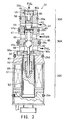
- the first embodiment of the capacity control valve 30 (Figs 1 and 2) is made up of a first control valve 30A, a second control valve 30B, and a solenoid unit 30C.
- the first control valve 30A has two ports 41 and 42 formed in a body 40.
- Port 41 receives the discharge pressure PdH from the discharge chambers 33 through the third communication hole 38 of the rear housing 31 shown in Fig. 1.
- Port 42 outputs refrigerant at discharge pressure PdL that has been reduced at the first control valve 30A, for delivery through the fourth communication hole 39 and a high-pressure refrigerant line 2.
- a bored valve hole 45 for communication of refrigerant, the upstream edge of which is intended to function as a first valve seat 45a.
- an e.g. ball-shaped first valve element (ball valve element) 46 is placed in an upstream space adjacent to the first valve seat 45a.
- the valve hole space communicating with the port 41 accommodates a coil spring 48 that urges the ball valve element 46 in the direction that it closes the passage, and the amount of that spring load can be adjusted by an adjustment screw 47 screwed into the body 40.
- the downstream side of the ball valve element 46 is in contact with one end of a shaft 49 that extends in the axial direction of the solenoid unit 30C through the valve hole of the first valve seat 45a.
- This shaft 49 is supported by a bearing 50a formed in the body 40, and the bearing 50a has a communication hole 50b to equalize the inside pressure of the solenoid unit 30C with the discharge pressure PdL.
- the solenoid unit 30C contains a solenoid coil 51 that has a cylindrical cavity, in which a sleeve 52 is fitted. A fixed core 53 is pressed into the sleeve 52.
- the sleeve 52 contains a plunger 54 that can slide in axial direction while being urged by a coil spring 55 in the downward direction in Fig. 2.
- the plunger 54 is fixed to the lower end of the shaft 49 running coaxially through the core 53.
- the plunger 54 When the solenoid coil 51 is in de-energized state, the plunger 54 is set away from the core 53 by coil spring 55, causing the shaft 49 extending from the plunger 54 to loose contact with the ball valve element 46.
- the first control valve 30A is fully closed because the freed ball valve element 46 is seated on the first valve seat 45a, being urged by another coil spring 48.
- the solenoid coil 51 When the solenoid coil 51 is energized, the plunger 54 is attracted by the magnetized core 53 to push the ball valve element 46 via the shaft 49 in the valve-opening direction.
- the amount of the thus caused movement, or the valve lift (or opening-degree) of the ball valve element 46 is proportional to the value of the supplied electrical current.
- control current determines the cross-sectional area of the refrigerant passageway of the first control valve 30A which functions as a variable orifice, and changes its cross-sectional size as specified by the control current to allow the discharged refrigerant to pass through.
- the solenoid unit 30C described above is intended, not for directly controlling a high-pressure refrigerant flow, but for controlling the first control valve 30A so that a small differential pressure will be produced depending on the discharge flow rate Qd of the refrigerant passing therethrough. Since only a small power is needed to achieve the purpose, it is possible to reduce the size of the solenoid unit 30C.
- the second control valve 30B has a body 40a screwed into the body 40 of the first control valve 30A so that the two control valves 30A and 30B are stacked in series.
- the body 40a has two ports 43 and 44.
- One port 43 is used to apply control pressure Pc to the crank chamber, and the other port 44 is used to introduce discharge pressure PdL that has been reduced at the first control valve 30A.
- the body 40a has an opening at its bottom end, which communicates with the port 41 to receive discharge pressure PdH of the discharge chambers 33 through a communication hole 47a formed on an adjustment screw 47.
- a second valve seat 56 is formed as an integral part of the body 40a. Placed opposite to this second valve seat 56 in the port 43 is a second valve element 57.
- the second valve element 57 is a taper-shaped member that is integrally formed with a cylindrical piston 58 which is axially movable within a cylinder that is bored on the axis of the body 40a.
- a coil spring 60 installed at an upper end portion of the piston 58 urges the second valve element 57 in the valve-closing direction.
- the respective spring load depends on how deep an adjustment screw 59 is screwed into the body 40a.
- the adjustment screw 59 has a central through hole 59a as a passage introducing the reduced discharge pressure PdL from the port 44 to the space above the piston 58.
- the second valve element 57 and the piston 58 thus receive different axial pressures at their both endfaces.
- the second valve element 57 receives discharge pressure PdH from the port 41, while the piston 58 receives discharge pressure PdL from the port 44.
- the then created differential pressure ⁇ P determines the lift of the second valve element 57. More specifically, the differential pressure ⁇ P is generated when refrigerant flows through a passage with a certain cross-sectional area as determined by the first control valve 30A. Then the second control valve 30B functions as a constant differential pressure valve that controls the amount of refrigerant flowing into the crank chamber 15 in such a way that the above differential pressure ⁇ P will be maintained at a constant level.
- O-rings are provided around the periphery of the capacity control valve 30, namely an O-ring 29a to seal the gap between the ports 44 and 43, an O-ring 29b between the ports 43 and 41, yet another O-ring 29c between the ports 41 and 42, another O-ring 29d between the port 42 and the solenoid unit 30C, and yet another O-ring 29e to seal the solenoid unit 30C against the surrounding atmosphere.
- the swash plate 20 When the shaft 12 is driven, the swash plate 20 will wobble to produce reciprocating motion of the pistons 25 linked to the outer regions of the swash plate 20. Refrigerant is sucked from the suction chambers 32 into the cylinder block 16, is compressed and is discharged into the discharge chambers 33.
- the solenoid unit 30C When the solenoid unit 30C is de-energized the first control valve 30A is fully closed. Refrigerant discharged to the discharge chambers 33 is entered to the crank chamber 15 in its entirety via the second control valve 30B. The variable displacement compressor 1 runs in the minimum capacity mode.
- the first control valve 30A When a predetermined amount of control current is supplied to the solenoid unit 30C, the first control valve 30A shows a predetermined opening degree (valve lift).
- the second valve element 57 and the piston 58 respond to the differential pressure ⁇ P across the first control valve 30A.
- the second control valve 30B controls the flow from the discharge chambers 33 to the crank chamber 15 such that the differential pressure ⁇ P will be maintained at a constant level. This control action may vary the capacity of the variable displacement compressor 1 as needed to regulate the discharge flow.
- the discharge flow rate is determined depending on how much refrigeration capacity is required in the present refrigeration cycle.
- the refrigeration capacity is calculated from various parameters, which include: engine rotation speed, vehicle speed, accelerator pedal position, indoor and outdoor temperatures, set temperatures, and monitoring signals supplied from various temperature and pressure sensors.
- the amount of the electrical current for the solenoid coil 51 is determined on the basis of this calculation result.
- the discharge flow rate is increased accordingly.
- This develops an increased differential pressure ⁇ P across the first control valve 30A.
- the second control valve 30B further lifts its valve element, so that more refrigerant will be supplied from the discharge chambers 33 to the crank chamber 15.
- the pressure Pc rises, and the variable displacement compressor 1 is controlled in an output-reducing condition.
- the compressor 1 now operates with a smaller discharge capacity, suppressing the discharge flow rate of refrigerant, and thus reducing the differential pressure ⁇ P.
- the discharge flow rate Qd of refrigerant is regulated by controlling the second control valve 30B so that the differential pressure across the orifice (i.e., the first control valve 30A being configured as a proportional solenoid valve) will be maintained at a constant level.
- the discharge flow rate will decrease and reduce the differential pressure across the first control valve 30A accordingly.
- the discharge pressure PdH falls, and the second control valve 30B operates such as to reduce the refrigerant flow from the discharge chambers 33 to the crank chamber 15.
- Pressure Pc in the crank chamber 15 falls and causes the compressor 1 to operate in a capacity-increasing condition, thus recovering the discharge. In this way, the discharge flow rate Qd of refrigerant is maintained at the constant level.
- the present invention combines the first control valve 30A that functions as a variable orifice controlled by the solenoid unit 30C and 'the second control valve 30B that controls the pressure in the crank chamber 15 in an integrated way, thus providing a compact, space-saving design for the capacity control functions (i.e., regulating the flow rate Qd of refrigerant discharged from the variable displacement compressor 1).
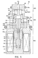
- the capacity control valve 30 of the second embodiment differs from the first embodiment of Fig. 2 in that the ball valve element 46 of its first control valve 30A is arranged such that it will allow more refrigerant to pass through when it is displaced following the stream of the refrigerant.
- the ball valve element 46, or the first valve element is placed on the downstream side of the first valve seat 45a.
- the plunger 54 and the core 53 have swapped their positions in the solenoid unit 30C.
- the first control valve 30A stays fully closed by the coil spring 55 when the solenoid unit 30C is not energized. Refrigerant entering the port 41 at discharge pressure PdH is led to the crank chamber 15 in its entirety through the second control valve 30B, meaning that the variable displacement compressor 1 now operates in the minimum capacity condition.
- the capacity control valve 30 of the third embodiment in Fig. 4 differs from Figs 2, 3 in that a taper-shaped valve element 61 is placed on the upstream side of the first valve seat 45a to receive a force in the valve-opening direction. Instead of port 44, the capacity control valve 30 in Fig. 4 has a communication hole 62 in the body 40 to serve the same purpose. For that reason, the port 41 for discharge pressure PdH and port 42 for discharge pressure PdL have swapped their positions in Fig. 4 compared to Fig. 3. Another difference is that the crank chamber 15 receives the discharge pressure PdL behind an orifice.
- the first control valve 30A in Fig. 4 has a port 41 formed in the body 40 to receive the discharge pressure PdH from the discharge chambers 33.
- Port 42 serves to supply the high-pressure refrigerant line 2 with discharge pressure PdL that is reduced by the first control valve 30A.
- the valve hole 45 communicates between the ports 41 and 42, and its upstream-side edge function as the first valve seat 45a.
- a taper-shaped first valve element 61 is placed in an upstream-side space, opposite to the first valve seat 45a.
- the first valve element 61 has an integrated circumferential flange 61 a.
- the flange 61a retains one end of a coil spring 48 that is placed around the first valve element 61 and abuts around the first valve seat 45a.
- the coil spring 48 urges the first valve element 61 in opening direction.
- the valve element 61 is coupled to an end of the axial shaft 49 of the solenoid unit 30C. With the solenoid unit 30C de-energized, the coil spring 55 seats the first valve element 61 on the first valve seat 45a.
- the shaft 49 is supported by a bearing 50a at its middle portion adjacent to the first control valve 30A, as well as by another bearing 50c at its bottom end.
- the bottom-end bearing 50c is press-fitted into the central bore of the fixed core 53.
- the second control valve 30B is coupled in series with the first control valve 30A, the space above the piston 58 being closed by a lid 59b.
- the body 40 has a communication hole 62 to communicate that space with the port 41, through which discharge pressure PdH acts on the back face of the piston 58. This arrangement reduces the needed number of ports of the body 40, thus making it easier to manufacture the capacity controlling section 300, and allows to eliminate some of the otherwise needed O-rings.
- the first control valve 30A sets a certain cross-sectional area for the refrigerant passageway in accordance with how much the solenoid unit 30C is energized.
- the second control valve 30B is responsive to differential pressure developed across the first control valve 30A to control the flow rate of refrigerant supplied from the discharge chambers 33 to the crank chamber 15.
- the capacity control valve 30 regulates the flow rate Qd that the variable displacement compressor 1 discharges.
- the capacity control valve 30 of Fig. 5 is distinct in the following points.
- the first control valve 30A employs a spool-shaped valve element 63 as the first valve element.
- the second control valve 30B uses a taper-shaped valve element 64 as a second valve element.
- a first valve seat 63a is provided as an integral part of the second valve element in the second control valve 30B.
- This first valve seat 63a is designed to set a required cross-section area for refrigerant passage while moving together with the second valve element.
- the second control valve 30B in Fig. 5 has a second valve seat 56 and its corresponding second valve element 64 with a tapered shape.
- the second valve seat 56 is formed as an integral part of the body 40, in the middle of a refrigerant passageway between the two ports 41 and 43, the former receiving refrigerant from the discharge chambers 33 and the latter delivering refrigerant to the crank chamber 15.
- the second valve element 64 is located in an upstream-side space (discharge pressure PdH).
- the second valve element 64 is urged by a coil spring 66 in the valve-opening direction.
- Integrally formed with the second valve element 64 is a pressure responsive member 64a, whose base portion detects differential pressure between two different discharge pressures PdH and PdL.
- the pressure responsive member 64a is installed inside the body 40 in a manner that it can come in contact with or move away from the second valve seat 56 according to the differential pressure acting thereon.
- the pressure responsive member 64a has a central cavity around its axis, the bottom end of which is open.
- the pressure responsive member 64a has also a hole 64b in its upper portion, which allows the discharge pressure PdH in the port 41 to reach the central cavity.
- the first control valve 30A has a first valve seat 63a at the rim of the bottom opening end of the pressure responsive member 64a.
- the value seat 63a cooperates with the spool-shaped valve element 63 located below the bottom opening.
- the first valve seat 63a and first valve element 63 set an appropriate cross-sectional area for a passageway that delivers refrigerant from one port 41 to another port 42 via the hole 64b of the pressure responsive member 64a.
- the valve element 63 is integrally formed with a pressure responsive piston 63p having the same cross-sectional area as the valve hole of the first valve seat 63a.
- a flange 63b is formed around this valve element 63, on a downstream-side portion remote from the first valve seat 63a. This flange 63b receives the force of the coil spring 48 urging the valve element 63 in the valve-opening direction.
- Another coil spring 60 is disposed between the pressure responsive piston 63p and the pressure responsive member 64a.
- the pressure responsive piston 63p is slidably supported in a plug 40b, which seals the bottom of the body 40.
- the pressure responsive piston 63p may also be pressed upward by the shaft 49 between the solenoid unit 30C and the bottom endface of the piston 63p.
- a pressure balancing hole 65 extends through the pressure responsive piston 63p to introduce the back pressure from the upstream-side cavity adjacent to the first valve seat 63a. This structure permits the discharge pressure PdH from the port 41 to act equally on both the bottom end of the pressure responsive piston 63p and the top end of the valve element 63. Those two opposing pressure forces cancel each other and the discharge pressure PdH never interferes with the operation of the solenoid unit 30C controlling the position of the valve element 63.
- the shaft 49 moves downward and allows the valve element 63 to leave the first valve seat 63a and to form a gap of a certain width around the first valve seat 63a.
- the refrigerant in the port 41 at discharge pressure PdH flows out of the port 42 through the first control valve 30A.
- the pressure responsive member 64a receives the differential pressure between discharge pressures PdH and PdL, which moves the second valve element 64 so that the differential pressure will become a predetermined level.
- the second control valve 30B controls the refrigerant being delivered from the port 43 to the crank chamber 15.
- the compressor 1 operates with a smaller displacement so as to recover the original discharge flow rate. If the refrigerant flow through the first control valve 30A decreases, the second control valve 30B is actuated in a valve-closing direction, thus reducing the refrigerant flow into the crank chamber 15. The compressor 1 operates with a larger displacement to regulate the discharge flow rate Qd.
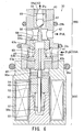
- the fifth embodiment of the capacity control valve 30 of Fig. 6 differs from the fourth embodiment (Fig. 5) in that the port 41 for discharge pressure PdH and the port 42 for discharge pressure PdL have swapped their positions.
- the fifth embodiment in Fig. 6 employs a ball valve element 67 for that purpose. This ball valve element 67 is located downstream of the second valve seat 56 and is loaded in valve-opening direction by a stem 68 extending through the valve hole and the first control valve 30A.
- the second control valve 30B has the second valve seat 56 formed as an integral part of the body 40.
- a ball valve element 67 is located in a downstream-side space adjacent to the second valve seat 56 and is urged by the coil spring 60 in valve-closing direction.
- the spring load can be adjusted by an adjustment screw 59 which has a central through hole 59a constituting the port 43 for delivery of refrigerant to the crank chamber 15 (control pressure Pc).
- the first control valve 30A has the first valve seat 63a at the bottom opening end of the pressure responsive member 64a which is integral with the shaft or stem 68.
- the upper end of the shaft or stem 68 contacts the ball valve element 67.
- the coil spring 55 urges the plunger 54 and shaft 49 in the upward direction to put the valve element 63 into the central opening of the pressure responsive member 64a.
- the first control valve 30A is fully closed, while the second control valve 30B is fully opened because of the differential pressure that acts on the pressure responsive member 64a.
- the shaft 49 moves downward and allows the valve element 63 to leave the first valve seat 63a and to form a gap of a certain width around the first valve seat 63a.
- the refrigerant in the port 41 at discharge pressure PdH flows out of the port 42 through the first control valve 30A.
- the pressure responsive member 64a receives differential pressure between discharge pressures PdH and PdL, which moves the ball valve element 67, relative to the second valve seat 56 so that the differential pressure will have a predetermined level.
- the second control valve 30B controls the flow rate of the refrigerant as delivered from the port 43 to the crank chamber 15.
- the compressor 1 operates with smaller displacement so as to recover its original discharge flow rate. If the refrigerant flow through the first control valve 30A decreases, the second control valve 30B is actuated in a valve-closing direction, thus reducing the refrigerant flow into the crank chamber 15. The compressor 1 operates with a larger displacement so as to regulate the discharge flow rate Qd.
- the capacity control valve 30 of the sixth embodiment in Fig. 7 differs from the fifth embodiment (Fig. 6) in that its first control valve 30A employs a taper-shaped valve element 61 as a first valve element located in an upstream-side space adjacent to the first valve seat 63a, being urged in the valve-opening direction.
- the coil spring 55 urges the plunger 54 and shaft 49 upward to seat the taper-shaped valve element 61 on the first valve seat 63a.
- the first control valve 30A is fully closed, while the second control valve 30B is fully opened because of the differential pressure that acts on the pressure responsive member 64a.
- the shaft 49 moves downward and allows the valve element 61 to leave the first valve seat 63a to form a gap of a certain width at the first valve seat 63a.
- the refrigerant from the port 41 at discharge pressure PdH flows out of the port 42 through the first control valve 30A.
- the pressure responsive member 64a receives the differential pressure between discharge pressures PdH and PdL, which moves the ball valve element 67 so that the differential pressure will have a predetermined level.
- the second control valve 30B controls the flow rate of the refrigerant being delivered from the port 43 to the crank chamber 15.
- valve element 67 opens further to supply more refrigerant into the crank chamber 15.
- the compressor 1 operates with a smaller displacement so as to recover its original discharge flow rate. If the refrigerant flow through the first control valve 30A decreases, the second control valve 30B is actuated in valve-closing direction reducing the refrigerant flow into the crank chamber 15. The compressor 1 operates with a larger displacement so as to regulate the discharge flow rate Qd.
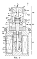
- the capacity control valve 30 of the seventh embodiment in Fig. 8 differs from the sixth embodiment (Fig. 7) in that its first valve element 61 is designed to cancel the back pressure in order to prevent the discharge pressure PdH from affecting operation of the first control valve 30A. This concept is described for the fifth embodiment (Fig. 6) already.
- the coil spring 55 urges the plunger 54 and shaft 49 in the upward direction to seat the taper-shaped valve element 61 on the first valve seat 63a.
- the first control valve 30A is fully closed, while the second control valve 30B is fully opened.
- the shaft 49 moves downward and allows the valve element 61 to leave the first valve seat 63a and form a gap of a certain width at the first valve seat 63a.
- the refrigerant at port 41 at discharge pressure PdH flows out of the port 42 through the first control valve 30A.
- the pressure responsive member 64a receives differential pressure between discharge pressures PdH and PdL and moves the valve element 67 so that the differential pressure will have a predetermined level.
- the second control valve 30B controls the flow rate at port 43 to the crank chamber 15.
- the compressor 1 operates with a smaller displacement so as to recover its original discharge flow rate. If the refrigerant flow through the first control valve 30A decreases, the second control valve 30B is actuated in a valve-closing direction to reduce the refrigerant flow into the crank chamber 15. The variable displacement compressor 1 operates with a larger displacement so as to regulate the discharge flow rate Qd.
- the capacity control valve 30 of the eighth embodiment in Fig. 9 differs from the fourth embodiment (Fig. 5) in that its first valve seat 45a is not designed to move, but is an integral part of the body 40 of the first control valve 30A. Another difference is that a plurality of ball valve elements 46 are employed to serve with several valve seats the function of the first valve element.
- the body 40 in Fig. 9 has a plurality of valve holes 45 bored along a pitch circle concentric with a cross section of the body 40 itself.
- the bottom-end edge of each valve hole 45 serves as the first valve seat 45a.
- Each ball valve element 46 is placed at a downstream-side space adjacent to each first valve seat 45a. All ball valve elements 46 rest on a downstream-side surface of a support member 70, which is urged by a coil spring 60 in the downward direction.
- the support member 70 also receives an upward force of the coil spring 55 in the solenoid unit 30C, via the plunger 54 and the shaft 49.
- the second control valve 30B has the pressure responsive member 64a urged upward by the coil spring 66. Since the pressure responsive member 64a is integral with the second valve element 64, the urging force of the coil spring 66 also acts on the second valve element 64 in the valve-closing direction.
- the pressure responsive member 64a, in combination with the second valve element 64, is supposed to be responsive to differential pressure ⁇ P between two different discharge pressures PdH and PdL, on the upstream and downstream ends of the first control valve 30A, respectively.
- the solenoid unit 30C When the solenoid unit 30C is de-energized, the coil spring 55 urges the plunger 54 and the shaft 49 in the upward direction and seats the ball valve elements 46 at the first valve seats 45a.
- the first control valve 30A is fully closed. With the discharge pressure PdH in the port 41, the maximum differential pressure acts on the pressure responsive member 64a, and fully opens the second control valve 30B.
- the compressor 1 operates in the minimum capacity condition.
- the compressor 1 operates with a smaller displacement so as to recover its original discharge flow rate. If the refrigerant flow through the first control valve 30A decreases, the second control valve 30B reduces the refrigerant flow into the crank chamber 15 because the pressure responsive member 64a impels the second valve element 64 in the valve-closing direction. The compressor 1 operates with a larger displacement so as to regulate the discharge flow rate Qd.
- the capacity control valve 30 of the ninth embodiment in Fig. 10 differs from the eighth embodiment (Fig. 9) in the structure of the first valve element and the first valve seat.
- the body 40 has a doughnut-shaped valve hole 45 hollowed along a circle that is concentric with a cross section of the body 40, and the bottom-end edge of the valve hole serves as the first valve seat 45a.
- the doughnut-shaped valve hole 45 does not go through the body 40 over the entire circumference, but some middle part of a floor of the body 40 remains solid at a few places. This measure connects the central portion of the floor to the circumferential portion of the body 40 in order to house the pressure responsive member 64a.
- a flat annular valve element 71 is disposed on the downstream side, together with a plug 40b that supports the flat valve element 71 axially movable.
- the solenoid unit 30C When the solenoid unit 30C is de-energized, the coil spring 55 urges the plunger 54 and the shaft 49 in the upward direction to abut the flat valve element 71 on the first valve seat 45a.
- the first control valve 30A is fully closed. With the discharge pressure PdH in the port 41, the maximum differential pressure acts on the pressure responsive member 64a fully opening the second control valve 30B.
- the compressor 1 operates in the minimum capacity condition.
- the compressor 1 operates with a smaller displacement so as to recover its original discharge flow rate. If the refrigerant flow through the first control valve 30A decreases, the second control valve 30B reduces the refrigerant flow into the crank chamber 15 because its pressure responsive member 64a impels the second valve element 64 in the valve-closing direction. The compressor 1 operates with a larger displacement so as to regulate the discharge flow rate Qd.
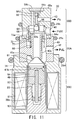
- the capacity control valve 30 of the tenth embodiment in Fig. 11 differs from the first embodiment (Fig. 2). The most prominent difference is that the tenth embodiment uses, in its first control valve 30A, a diaphragm 72 to detect differential pressure between upstream and downstream sides.
- an integral cylinder 40c is formed serving as the valve hole 45 interconnecting the ports 41 and 42.
- the bottom end of the cylinder 40c functions as the first valve seat 45a for the first control valve 30A.
- a taper-shaped valve element 61 is placed opposite the first valve seat 45a.
- This valve element 61 is integral with the plunger 54 of the solenoid unit 30C and has a circumferential groove 61b in the round periphery.
- the groove 61b receives a piston ring 74 slidably supporting the plunger 54 on the inner wall of the sleeve 52, and also centering the valve element 61 on the axis of the sleeve 52.
- a valve hole is bored between ports 41, 43.
- the bottom end of the valve hole is the second valve seat 56.
- the taper-shaped second valve element 64 is placed in the upstream-side space adjacent to the second valve seat 56.
- the taper-shaped second valve element 64 is placed in the upstream-side space adjacent to the second valve seat 56.
- Integrally formed on top of the second valve element 64 are a shaft 64c and a piston 64d.
- This piston 64d has the same outer diameter as the valve hole of the second valve seat 56.
- the endface of the piston 64d remote from the second valve element 64 receives, through a communication hole 62, discharge pressure PdH in the port 41, so that the second valve element 64 is actuated solely by the differential pressure between discharge pressures PdH and PdL, without being affected by the absolute value of discharge pressure PdH.
- the second valve element 64 is integral with a base member 64e, which is larger in diameter than the second valve element 64.
- the base member 64e has a hole 64
- a sliding member 73 surrounds the outer surface of the cylinder 40c in body 40 in a way that it can move in the vertical direction.
- This sliding member 73 is connected with the inner surface of the cavities of the bodies 40 and 40a via a diaphragm 72, which is a doughnut-shaped sheet with a center hole.
- the outer circumference of the diaphragm 72 is clamped between the bodies 40 and 40a.
- the body 40a is pressed into the body 40.
- the inner circumference of the diaphragm 72 is clamped between the sliding member 73 and a ring 73a.
- the base member 64e of the second valve element 64 may rest on the sliding member 73.
- Two coil springs 60 and 66 urge the members 64e and 73 such that they will keep contact.
- the diaphragm 72 receives differential pressure between the discharge pressure PdH at the port 41 and the discharge pressure PdL at the port 42. This differential pressure displaces the sliding member 73 in axial direction, causing the second valve element 64 to move toward or away from the second valve seat 56.
- the solenoid unit 30C When the solenoid unit 30C is de-energized, the coil spring 55 urges the plunger 54 upward to seat the valve element 61 sit on the first valve seat 45a.
- the first control valve 30A is fully closed. With the discharge pressure PdH present in the port 41, the maximum differential pressure acts on the diaphragm 72 to fully open the second control valve 30B.
- the compressor 1 operates in the minimum capacity condition.
- the plunger 54 moves downward allowing the valve element 61 to leave the first valve seat 45a and to form a gap of a certain width at the first valve seat 45a.
- Refrigerant in the port 41 at the discharge pressure PdH flows out of the port 42 through the hole 64b of the second valve element 64, the central cavity of the cylinder 40c, and the first control valve 30A.
- the diaphragm 72 receives the differential pressure between the two different discharge pressures PdH and PdL, and moves the sliding member 73 upward so that the differential pressure will reach a predetermined level.
- the second valve element 64 follows this movement of the sliding member 73, thus controlling the refrigerant at the discharge pressure PdH that flows through the second control valve 30B.
- the compressor 1 operates with a smaller displacement so as to recover its original discharge flow rate. If the refrigerant flow through the first control valve 30A decreases, the diaphragm 72 receives a reduced differential pressure and reduces the refrigerant flowing into the crank chamber 15 because its sliding member 73 impels the second valve element 64 in the valve-closing direction. The compressor 1 operates with a larger displacement so as to regulate the discharge flow rate Qd.
- the second control valve 30B is controlled to respond only to the differential pressure between the two different discharge pressures PdH and PdL, because the second valve element 64 is unaffected by variations of the discharge pressure PdH.
- the capacity control valve 30 of the eleventh embodiment of Fig. 12 differs from the tenth embodiment (Fig. 11) in that the taper-shaped valve element (first valve element) 61 in the first control valve 30A is disposed in an upstream-side space of the first valve seat 45b formed at the top end of the cylinder 40c. For this reason, in the solenoid unit 30C, the plunger 54 and core 53 have swapped their positions on the axis (relative to Fig. 11).
- the shaft 49 connects the first valve element 61 with the plunger 54 in the solenoid unit 30C.
- the first valve element 61 is urged by the coil spring 55 in the valve-closing direction.
- the eleventh embodiment operates basically in the same way as the tenth embodiment.
- the widened base member 64e of the second valve element 64 has at least one round hole 64f in a cylindrical skirt portion in addition to the hole 64b to deliver the discharge pressure PdH from the port 41 to the upstream side of the first valve element 61.
- variable displacement compressor 1 operates in the minimum capacity condition.
- the plunger 54 moves upward and allows the taper-shaped valve element 61 to leave the first valve seat 45b and form a gap of a certain width at the first valve seat 45b.
- Refrigerant in the port 41 at discharge pressure PdH flows out of the port 42 through the round hole 64f and the hole 64b of the second valve element 64, the first control valve 30A, and the central cavity of the cylinder 40c.
- the diaphragm 72 receives differential pressure between the two different discharge pressures PdH and PdL and moves the sliding member 73 upward so that the differential pressure will reach a predetermined level.
- the second valve element 64 follows this upward movement of the sliding member 73, thus controlling the flow rate of the refrigerant at discharge pressure PdH that flows through the second control valve 30B.
- the second valve element 64 is moved to further open and to supply more refrigerant into the crank chamber 15.
- the compressor 1 operates with a smaller displacement so as to recover its original discharge flow rate. If the refrigerant flow through the first control valve 30A decreases, the diaphragm 72 detects and responds to a reduced differential pressure.
- the sliding member 73 impels the second valve element 64 in the valve-closing direction.
- the second control valve 30B reduces the refrigerant supplied to the crank chamber 15, and the compressor 1 operates with a larger displacement so as to regulate the discharge flow rate Qd.
- the first control valve 30A is located between the discharge chambers 33 and crank chamber 15, and the pressure in the crank chamber 15 is controlled by varying the flow rate at discharge pressure PdL from the discharge chambers 33 into the crank chamber 15.
- the twelfth embodiment of Fig. 13 controls the flow rate returning from the crank chamber 15 back into the suction chambers 32.
- the variable displacement compressor 1 has an orifice of fixed cross-section in the middle of a passageway that delivers refrigerant from the discharge chambers 33 to the crank chamber 15.
- the first control valve 30A and solenoid unit 30C of the capacity control valve 30 of Fig. 13 have almost the same structure shown in the third embodiment of Fig. 4. An exception is that the first control valve 30A is designed to route the discharged refrigerant in the direction that the stream pushes the taper-shaped valve element 61 in opening direction away from the first valve seat 45a.
- two pistons 58 and 58a are integrally formed with the second valve element 57.
- the pistons 58 and 58a have the same outer diameter as the valve hole of the second valve seat 56.
- Discharge pressure PdH acts on the piston 58a and discharge pressure PdL propagates through a communication hole 62 and acts on one endface of the piston 58.
- Pressure Pc of the crank chamber 15 is led from the port 43 to an upstream-side cavity adjacent to the second valve element 57.
- the downstream-side room communicates with the suction chambers 32 at suction pressure Ps via the port 75.
- the second valve element 57 and piston 58 are responsive to the differential pressure ⁇ P developed across the first control valve 30A, which is functioning here as an orifice.
- the second control valve 30B thus controls the flow rate from the crank chamber 15 to the suction chambers 32 such that the differential pressure ⁇ P will be maintained at a constant level. This control action varies the capacity of the variable displacement compressor 1 so as to regulate the discharge flow rate.
- the coil spring 55 urges the plunger 54 and the shaft 49 upward to seat the first valve element 61 on the first valve seat 45a.
- the first control valve 30A is fully closed.
- the plunger 54 moves downward and allows the first valve element 61 to leave the first valve seat 45a and to form a gap of a certain width at the first valve seat 45a.
- Refrigerant in the port 41 at discharge pressure PdH flows out of the port 42 through the first control valve 30A.
- the second valve element 57 and the piston 58 receive differential pressure between the two different discharge pressures PdH and PdL, in addition to the force of the coil spring 60.
- the second valve element 57 moves to a point at which all those forces and pressures are in balance.
- the refrigerant in the crank chamber 15 at pressure Pc is allowed to flow back to the suction chambers 32.
- the second control valve 30B now may control the discharge capacity of the variable displacement compressor 1 by varying the crank chamber pressure Pc.
- the refrigerant flow through the first control valve 30A may increase due to, for example, sudden acceleration of the driving engine. Then, a larger differential pressure will occur across the valve 30A and will actuate the second control valve 30B to further close and to reduce the flow rate out of the crank chamber 15.
- the compressor 1 operates with a smaller displacement so as to recover its original discharge flow rate. If the refrigerant flow through the first control valve 30A decreases, the second control valve 30B is actuated in the valve-opening direction, thus increasing the flow rate out of the crank chamber 15.
- the compressor 1 operates with a larger displacement, thus regulating the discharge flow rate Qd.
- the third embodiment has a capacity control valve 30 controlling the flow rate into the crank chamber 15 (inflow control).
- the twelfth embodiment (Fig. 13) manipulates the flow rate out of the crank chamber 15 (outflow control).
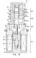
- the thirteenth embodiment of Fig. 14 relates to a capacity control valve 30 that employs both in-flow and out-flow control mechanisms.
- the capacity control valve 30 of Fig. 14 has a first control valve 30A placed in a passageway leading from the discharge chambers 33 to the solenoid unit 30C that governs the cross-sectional area of the passageway.
- the capacity control valve 30 of Fig. 14 has the second 30B and a third control valves 30D that both detect the differential pressure developed across the first control valve 30A and which control the pressure in the crank chamber 15 such that the differential pressure will reach a specified level.
- the second and third control valves 30B and 30D accommodate the following components in a common valve hole: a piston 58, a second valve element 57, and a third valve element 76, all integrally formed as a single member.
- One control edge formed in the valve hole serves as a third valve seat 77.
- the piston 58 has the same outer diameter as the valve seat 77.
- the second valve element 57 receives the discharge pressure PdH on its bottom endface, while the piston 58 receives the discharge pressure PdL through a communication hole 62 of the body 40.
- the upstream-side room adjacent to the second valve element 57 is at discharge pressure PdH introduced from the port 41.
- the downstream side communicates with the crank chamber 15 through another port 43a, the pressure at which is Pc1.
- the upstream-side space adjacent to the third valve element 76 receives pressure Pc2 from the crank chamber 15 via yet another port 43b.
- the downstream-side space adjacent to the third valve element 76 communicates with the suction chambers 32 at suction pressure Ps via still another port 75.
- the piston 58 and the second valve element 57 move together in response to the differential pressure ⁇ P across the first control valve 30A, which is functioning here as an orifice.
- the second and third control valves 30B and 30D act as a three-way valve that controls the inflow of refrigerant from the discharge chambers 33 into the crank chamber 15, simultaneously with the outflow from the crank chamber 15 to the suction chambers 32, so that the differential pressure ⁇ P will be maintained at a constant level.
- the capacity control valve 30 operates as follows. When the solenoid unit 30C is de-energized, the coil spring 55 urges the plunger 54 and the shaft 49 upward to seat the first valve element 61 on the first valve seat 45a. The first control valve 30A is fully closed.
- the plunger 54 moves downward causing the first valve element 61 to leave the first valve seat 45a and to form a gap of a certain width.
- Refrigerant in the port 41 at discharge pressure PdH flows out of the port 42 through the first control valve 30A.
- the unified valve member i.e., second valve element 57, third valve element 76, and the piston 58
- the second control valve 30B supplies the crank chamber 15 with refrigerant at discharge pressure PdH, and the third control valve 30D allows the refrigerant at pressure Pc to flow back into the suction chambers 32.
- the capacity control valve 30 varies the crank chamber pressure Pc in this way, thus being able to control the discharge capacity of the variable displacement compressor 1.
- the refrigerant flowing through the first control valve 30A may increase due to, for example, sudden acceleration of the driving engine. Then, a larger differential pressure will occur across the valve 30A. The increased differential pressure opens the second control valve 30B wider, while it actuates the third control valve 30D in valve-closing direction. This results in an increased inflow to the crank chamber 15, along with a decreased outflow from the crank chamber 15.
- the variable displacement compressor 1 operates with a smaller displacement so as to recover its original discharge flow rate. If the refrigerant flow through the first control valve 30A decreases, the second control valve 30B is actuated in valve-closing direction, thus producing a decreased inflow to the crank chamber 15. At the same time, the third control valve 30D is impelled in the valve-opening direction, increasing the outflow from the crank chamber 15.
- the compressor 1 now operates with a larger displacement, resulting in a regulated discharge flow rate Qd.
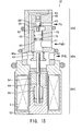
- the capacity control valve 30 of Fig. 15 is designed to control how much of the discharged refrigerant is supplied to the crank chamber 15. Another difference is that the second valve element 57 of the second control valve 30B is provided as a discrete component, and is not integrated with a pressure sensing member that responds to differential pressure across the first control valve 30A.
- a piston 58 is located inside the body 40.
- the communication hole 62 in the body 40 applies the discharge pressure PdL to the piston 58.
- a refrigerant passageway laterally branches halfway from the communication hole 62, to the port 43 for the crank chamber 15.
- the second valve seat 56 is formed as an integral part of the body 40.
- the second valve element 57 is integrally formed with the piston 58.
- the piston 58 receives the discharge pressure PdL on its distal end.
- a piston 78, a coil spring 79, and a spring seat 80 are installed coaxially with the second valve element 57 and the piston 58 in a space formed between the port 41 and the communication hole 62.
- the discharge pressure PdH is available in this space.
- a shaft integral with the second valve element 57 extends toward the piston 78 in a space that communicates with the communication hole 62.
- the piston 78 is forced against the shaft by the coil spring 79.
- Discharge pressure PdL does not affect the movement of the second valve element 57 and the piston 58 because their pressure-receiving areas are substantially equal.
- the piston 78 responds to the differential pressure ⁇ P developed across the first control valve 30A, which functions as an orifice.
- the second control valve 30B controls the flow rate from the discharge chambers 33 to the crank chamber 15 such that the differential pressure ⁇ P will be maintained at a constant level. This mechanism varies the capacity of the variable displacement compressor 1 so as to regulate the discharge flow rate.
- the coil spring 55 urges the plunger 54 and the shaft 49 to seat the first valve element 61 on the first valve seat 45a.
- the first control valve 30A is fully closed.
- the plunger 54 moves downward and allows the first valve element 61 to leave the first valve seat 45a and to form a gap of a certain width at the first valve seat 45a.
- Refrigerant in the port 41 at discharge pressure PdH flows out of the port 42 through the first control valve 30A.
- the piston 78 receives the differential pressure between the two different discharge pressures PdH and PdL while being pushed by two coil springs 60 and 79, and thus moves to a point at which all those forces and pressures are in balance.
- Refrigerant at discharge pressure PdH flows into the crank chamber 15.
- the second control valve 30B now controls the discharge capacity of the variable displacement compressor 1 by varying the crank chamber pressure Pc.
- the refrigerant flow through the first control valve 30A may increase due to, for example, sudden acceleration of the engine. Then, a larger differential pressure will occur across the valve 30A and will further open the second control valve 30B. This produces an increased inflow to the crank chamber 15, and as a result, the variable displacement compressor 1 operates with a smaller displacement, thus recovering its original discharge flow rate. If the refrigerant flow through the first control valve 30A decreases, the second control valve 30B is actuated in valve-closing direction to decreased the inflow to the crank chamber 15. The variable displacement compressor 1 operates with a larger displacement, resulting in a regulated discharge flow rate Qd.
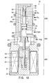
- the capacity control valve 30 of the fifteenth embodiment in Fig. 16 is similar to the twelfth embodiment (Fig. 13) and controls the outflow from the crank chamber 15 to the suction chambers 32, however, differs in that the second valve element 57 in its second control valve 30B is provided as a discrete component, not integrated with a pressure sensing member that responds to differential pressure across the first control valve 30A.
- the second control valve 30B employs the piston 78, the coil spring 79, and the spring seat 80.
- the ports 43 and 75 are disposed to communicate with the crank chamber 15 and suction chambers 32, respectively.
- a second valve seat 56 is formed as an integral part of the body 40.
- the second valve element 57 is installed in an upstream-side space near the port 43. Integrally formed with this second valve element 57 is the piston 58 with the same diameter as the valve hole of the second valve seat 56.
- Discharge pressure PdL propagates through the communication hole 62 of the body and acts on one endface of the piston 58.
- the second valve element 57 is integral with another piston 58a having nearly the same diameter as the valve hole of the second valve seat 56.
- This piston 58a is held in the body 40 in an airtight manner, movably in its axial direction, receiving discharge pressure PdL.
- the lower end of the piston 58a abuts on the piston 78.
- Discharge pressure PdL does not affect movement of the pistons 58a and 58 because their diameters are substantially the same.
- the piston 78 responds to the differential pressure ⁇ P across the first control valve 30A, functioning as an orifice.
- the second control valve 30B controls the outflow from the crank chamber 15 to the suction chambers 32 such that the differential pressure ⁇ P will be maintained at a constant level. This control action varies the capacity of the variable displacement compressor 1 to regulate the discharge flow rate.
- the coil spring 55 urges the plunger 54 and the shaft 49 to seat the first valve element 61 on the first valve seat 45a.
- the first control valve 30A is fully closed.
- the plunger 54 moves downward to allow the first valve element 61 to leave the first valve seat 45a and to form a gap of a certain width at the first valve seat 45a.
- Refrigerant in the port 41 at discharge pressure PdH flows out of the port 42 through the first control valve 30A.
- the piston 78 receives the differential pressure between discharge pressures PdH and PdL, while being pushed by the coil springs 60 and 79, and moves to a point at which all those forces and pressures are in balance.
- Refrigerant in the crank chamber 15 at pressure Pc is allowed to flow back into the suction chambers 32.
- the second control valve 30B now controls the discharge capacity of the variable displacement compressor 1 by varying the crank chamber pressure Pc.
- the refrigerant flow through the first control valve 30A may increase due to, for example, sudden acceleration of the driving engine. Then, a larger differential pressure will occur across the valve 30A and will actuate the second control valve 30B to further close and to reduce the flow rate out of the crank chamber 15 and to raise the crank chamber pressure Pc.
- the compressor 1 operates with a smaller displacement so as to recover its original discharge flow rate. If the refrigerant flow through the first control valve 30A decreases, the second control valve 30B is actuated in the valve-opening direction, increasing the outflow from the crank chamber 15. Since the crank chamber pressure Pc drops, the variable displacement compressor 1 now operates with a larger displacement, resulting in a regulated discharge flow rate Qd.
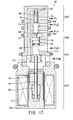
- the capacity control valve 30 of the sixteenth embodiment in Fig. 17 is similar to the thirteenth embodiment (Fig. 14), however, differs in that the second valve element 57 in the second control valve 30B is a discrete component, not integrated with a member that senses differential pressure across the first control valve 30A. As the pressure responsive member, the sixteenth embodiment in Fig. 17 has a similar structure to the fifteenth embodiment (Fig. 16).
- the piston 58, the second valve element 57, and the third valve element 76 are disposed in an integrated manner.
- the piston 58 has the same outer diameter as the valve holes of second and third valve seats 56 and 77 so as to avoid the effect of discharge pressure PdL acting thereon.
- the piston 58 and second valve element 57 move together in response to the differential pressure ⁇ P across the first control valve 30A, functioning as an orifice.
- the second and third control valves 30B and 30D serve as a three-way valve controlling the inflow from the discharge chambers 33 into the crank chamber 15, and simultaneously the outflow from the crank chamber 15 to the suction chambers 32, such that the differential pressure ⁇ P will be maintained at a constant level.
- the coil spring 55 urges the plunger 54 and the shaft 49 upward to seat the first valve element 61 on the first valve seat 45a.
- the first control valve 30A is fully closed.
- the plunger 54 moves downward to allow the first valve element 61 to leave the first valve seat 45a and to form a gap of a certain width.
- Refrigerant in the port 41 at discharge pressure PdH flows out of the port 42 through the first control valve 30A.
- the unified valve member i.e., second valve element 57, third valve element 76, and piston 58
- the second control valve 30B supplies refrigerant at pressure Pc1 to the crank chamber 15 by controlling the refrigerant at discharge pressure PdL, and at the same time, the third control valve 30D allows the refrigerant at pressure Pc2 in the crank chamber 15 to flow back into the suction chambers 32.
- the capacity control valve 30 varies the crank chamber pressure Pc in this way to control the discharge capacity of the variable displacement compressor 1.
- the refrigerant flow through the first control valve 30A may increase due to, for example, sudden acceleration of the driving engine. Then, a larger differential pressure will occur across that valve 30A which opens the second control valve 30B wider, while actuating the third control valve 30D in valve-closing direction. This control action produces an increased inflow to the crank chamber 15, together with a decreased outflow from the crank chamber 15.
- the compressor 1 operates with a smaller displacement so as to recover its original discharge flow rate. If the refrigerant flow through the first control valve 30A decreases, the second control valve 30B is actuated in the valve-closing direction, and the third control valve 30D in the valve-opening direction, thus producing a decreased inflow to the crank chamber 15 and an increased outflow from the crank chamber 15.
- the compressor 1 operates with a larger displacement, resulting in a regulated discharge flow rate Qd.
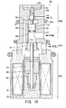
- the capacity control valve 30 of the seventeenth embodiment in Fig. 18 is designed to control how much of the discharged refrigerant to supply to the crank chamber 15.
- the second valve element 57 of the second control valve 30B is provided as a discrete component, not integrated with a member that responds to differential pressure across the first control valve 30A.
- the seventeenth embodiment is, however, different in that it has no back-pressure cancellation mechanism for the second valve element 57.
- the second control valve 30B in Fig. 18 is constructed as follows.
- the second valve element 57 is urged by the coil spring 60 in valve-closing direction.
- the discharge pressure PdL is routed through the communication hole 62 in the body 40 and acts only on the piston 78 and the second valve element 57.
- the upper end of the coil spring 60 is supported by a lid 59c having a vent.
- An O-ring 29b is used for sealing the capacity control valve 30 when installed in the variable displacement compressor 1.
- the upper space above the level of this O-ring 29b will be at pressure Pc, i.e., the pressure in the port 43, meaning that the same pressure Pc will be available in the cavity of the coil spring 60.
- the capacity control valve 30 of Fig. 18 bears close resemblance to the fourteenth embodiment (Fig. 15) in terms of the structure, except for the fact that the second valve element 57 is not free from back pressures.
- the capacity control valve 30 operates as the fourteenth embodiment. This similarity of the control operations also applies when the solenoid unit 30C is energized, or when the engine rotation speed varies.
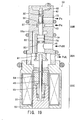
- the capacity control valve 30 of the eighteenth embodiment in Fig. 19 is designed to control the outflow of the crank chamber 15 to the suction chambers 32.
- the second valve element 57 of the second control valve 30B is a discrete component, not integrated with a member that senses differential pressure across the first control valve 30A.
- the eighteenth embodiments is, however, different in that it has no back-pressure cancellation mechanism for the second valve element 57.
- the second control valve 30B in Fig. 19 is constructed as follows.
- the second valve element 57 is urged against the piston 78 by the coil spring 60 in the valve-opening direction.
- the discharge pressure PdL is routed through the communication hole 62 such that it acts only on the piston 78 and on another piston that extends from the second valve element 57.
- the piston 58 is integrally formed with the second valve element 57, and the coil spring 60 is accommodated in a space between this piston 58 and the lid 59c having a vent.
- the coil spring space is pressurized at Ps through the vent in the lid 59c.
- the capacity control valve 30 of Fig. 19 bears close resemblance to the fifteenth embodiment (Fig. 16) in terms of the structure, except for the fact that the second valve element 57 is not free from back pressures.
- the solenoid unit 30C When the solenoid unit 30C is de-energized, the capacity control valve 30 operates in the same way as described in the fifteenth embodiment. This similarity in its control operations also applies when the solenoid unit 30C is energized and when the engine rotation speed varies.
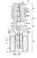
- the capacity control valve 30 of the nineteenth embodiment in Fig. 20 controls both inflow and outflow of refrigerant to/from the crank chamber 15, as the seventeenth embodiment (Fig. 18).
- the second and third control valves 30B and 30D are constructed as follows.
- the second valve element 57 and the third valve element 76 which constitute a three-way valve, are urged by the coil spring 60 in valve-closing direction and in the valve-opening direction, respectively, where discharge pressure PdL is routed through the communication hole 62 such that it acts only on the second valve element 57 and the piston 78.
- the piston 58 is integrally formed with the second and third valve elements 57 and 76.
- the coil spring 60 is accommodated in a space between the piston 58 and the lid 59c having a vent. The coil spring space is pressurized at Ps through the vent in the lid 59c.
- the capacity control valve 30 of Fig. 20 bears close resemblance to the sixteenth embodiment (Fig. 17) in terms of the structure, except for the fact that the second valve element 57 and third valve element 76 are not free from back pressures.
- the capacity control valve 30 of Fig. 20 operates as the sixteenth embodiment. This similarity also applies when the solenoid unit 30C is energized and as when the engine rotation speed varies.
- the capacity control valves 30 share a common concept.
- the first control valve 30A controls the cross-sectional area of a passageway for discharged refrigerant.
- the second control valve 30B (and the third control valve 30D if provided in several cases) controls the pressure Pc in the crank chamber 15 such that the differential pressure across the controlled passageway will be maintained at a specified level.
- the capacity control valves as described should not be limited to a structure that uses the differential pressure on the discharge side of the valves. Rather, there could be provided a structure using the differential pressure on the suction side.
- the first control valve 30A may control the cross-section area of a passageway into the compressor, and the second control valve 30B (and the third control valve 30D if provided) controls the pressure Pc in the crank chamber 15 such that the differential pressure across the controlled passageway will be maintained at a specified level.
Landscapes
- Engineering & Computer Science (AREA)
- Mechanical Engineering (AREA)
- General Engineering & Computer Science (AREA)
- Compressors, Vaccum Pumps And Other Relevant Systems (AREA)
- Control Of Positive-Displacement Pumps (AREA)
- Air-Conditioning For Vehicles (AREA)
Applications Claiming Priority (2)
| Application Number | Priority Date | Filing Date | Title |
|---|---|---|---|
| JP2002278764A JP4130566B2 (ja) | 2002-09-25 | 2002-09-25 | 可変容量圧縮機用容量制御弁 |
| JP2002278764 | 2002-09-25 |
Publications (2)
| Publication Number | Publication Date |
|---|---|
| EP1403516A2 true EP1403516A2 (de) | 2004-03-31 |
| EP1403516A3 EP1403516A3 (de) | 2009-03-18 |
Family
ID=31973268
Family Applications (1)
| Application Number | Title | Priority Date | Filing Date |
|---|---|---|---|
| EP03021486A Withdrawn EP1403516A3 (de) | 2002-09-25 | 2003-09-23 | Regelventil für einen Verdichter variabler Verdrängung |
Country Status (3)
| Country | Link |
|---|---|
| US (1) | US20040057840A1 (de) |
| EP (1) | EP1403516A3 (de) |
| JP (1) | JP4130566B2 (de) |
Cited By (1)
| Publication number | Priority date | Publication date | Assignee | Title |
|---|---|---|---|---|
| WO2007016486A1 (en) * | 2005-07-29 | 2007-02-08 | Wagner Spray Tech Corporation | Automatic inlet check valve release in a paint pump |
Families Citing this family (12)
| Publication number | Priority date | Publication date | Assignee | Title |
|---|---|---|---|---|
| JPWO2005024233A1 (ja) * | 2003-09-02 | 2006-11-02 | 株式会社豊田自動織機 | 容量可変型斜板式圧縮機 |
| JP2005351207A (ja) * | 2004-06-11 | 2005-12-22 | Tgk Co Ltd | 可変容量圧縮機用制御弁 |
| JP4580816B2 (ja) * | 2005-05-25 | 2010-11-17 | カルソニックカンセイ株式会社 | 可変容量コンプレッサのトルク算出装置およびトルク算出方法 |
| JP2006327386A (ja) * | 2005-05-25 | 2006-12-07 | Calsonic Kansei Corp | 車両用空調装置 |
| JP4572272B2 (ja) * | 2005-07-26 | 2010-11-04 | 株式会社テージーケー | 可変容量圧縮機用制御弁 |
| JP4925800B2 (ja) * | 2006-11-30 | 2012-05-09 | カルソニックカンセイ株式会社 | 可変容量コンプレッサの制御弁 |
| JP4833820B2 (ja) * | 2006-12-25 | 2011-12-07 | 株式会社鷺宮製作所 | 容量制御弁および容量可変型圧縮機並びに空気調和装置 |
| FR2933471B1 (fr) * | 2008-07-03 | 2013-02-15 | Vianney Rabhi | Vanne electro-hydraulique a levee de bille pour centrale hydraulique de moteur a taux de compression variable |
| US10006502B2 (en) * | 2016-03-01 | 2018-06-26 | Borgwarner Inc. | Position force controlled actuator |
| CN110462212B (zh) * | 2017-03-28 | 2021-05-07 | 伊格尔工业股份有限公司 | 容量控制阀 |
| KR102051661B1 (ko) | 2017-05-30 | 2019-12-04 | 한온시스템 주식회사 | 컨트롤 밸브 및 가변 용량식 압축기 |
| EP3677820B1 (de) | 2017-08-28 | 2025-07-16 | Eagle Industry Co., Ltd. | Elektromagnetisches ventil |
Citations (1)
| Publication number | Priority date | Publication date | Assignee | Title |
|---|---|---|---|---|
| JP2001107854A (ja) | 1999-08-04 | 2001-04-17 | Toyota Autom Loom Works Ltd | 空調装置並びに容量可変型圧縮機の制御方法及び制御弁 |
Family Cites Families (34)
| Publication number | Priority date | Publication date | Assignee | Title |
|---|---|---|---|---|
| JPH0631614B2 (ja) * | 1986-04-17 | 1994-04-27 | 株式会社豊田自動織機製作所 | 可変容量圧縮機 |
| JPH0216072Y2 (de) * | 1987-05-27 | 1990-05-01 | ||
| JPH0387573A (ja) * | 1989-08-31 | 1991-04-12 | Saginomiya Seisakusho Inc | 冷媒用制御弁 |
| JPH03168484A (ja) * | 1989-11-24 | 1991-07-22 | Toyota Autom Loom Works Ltd | 流量制御弁 |
| JP3089775B2 (ja) * | 1991-12-16 | 2000-09-18 | 株式会社豊田自動織機製作所 | 可変容量圧縮機 |
| JPH0828742A (ja) * | 1994-07-15 | 1996-02-02 | Japan Atom Energy Res Inst | 高速電磁バルブ |
| US5702235A (en) * | 1995-10-31 | 1997-12-30 | Tgk Company, Ltd. | Capacity control device for valiable-capacity compressor |
| JPH09287798A (ja) * | 1996-04-23 | 1997-11-04 | Chugoku Furoo Controls:Kk | 空調機ユニット及び該ユニットを組み込んだ空調システム |
| JP3616462B2 (ja) * | 1996-07-30 | 2005-02-02 | 株式会社鷺宮製作所 | 電磁弁 |
| JP3585150B2 (ja) * | 1997-01-21 | 2004-11-04 | 株式会社豊田自動織機 | 可変容量圧縮機用制御弁 |
| JP3582284B2 (ja) * | 1997-03-13 | 2004-10-27 | 株式会社豊田自動織機 | 冷凍回路及び圧縮機 |
| JP4209522B2 (ja) * | 1998-11-27 | 2009-01-14 | カルソニックカンセイ株式会社 | 斜板式可変容量圧縮機 |
| JP3925006B2 (ja) * | 1999-02-02 | 2007-06-06 | 株式会社豊田自動織機 | 容量可変型圧縮機の制御弁 |
| JP2000230481A (ja) * | 1999-02-10 | 2000-08-22 | Toyota Autom Loom Works Ltd | 容量可変型圧縮機のクランク圧制御機構 |
| JP3583951B2 (ja) * | 1999-06-07 | 2004-11-04 | 株式会社豊田自動織機 | 容量制御弁 |
| JP3413385B2 (ja) * | 1999-08-18 | 2003-06-03 | 太平洋工業株式会社 | 冷媒流路の切換弁 |
| JP2001153044A (ja) * | 1999-09-10 | 2001-06-05 | Toyota Autom Loom Works Ltd | 容量可変型圧縮機の制御弁 |
| JP3991556B2 (ja) * | 1999-10-04 | 2007-10-17 | 株式会社豊田自動織機 | 容量可変型圧縮機の制御弁 |
| JP2001108138A (ja) * | 1999-10-08 | 2001-04-20 | Kayaba Ind Co Ltd | 電磁圧力制御弁 |
| JP2001132632A (ja) * | 1999-11-10 | 2001-05-18 | Toyota Autom Loom Works Ltd | 容量可変型圧縮機の制御弁 |
| JP2001221158A (ja) * | 1999-11-30 | 2001-08-17 | Toyota Autom Loom Works Ltd | 容量可変型圧縮機の制御弁 |
| JP3840354B2 (ja) * | 1999-12-01 | 2006-11-01 | 株式会社テージーケー | 電気制御膨張弁 |
| JP4221893B2 (ja) * | 2000-02-28 | 2009-02-12 | 株式会社豊田自動織機 | 容量可変型圧縮機の容量制御装置及び圧縮機モジュール |
| JP3735512B2 (ja) * | 2000-05-10 | 2006-01-18 | 株式会社豊田自動織機 | 容量可変型圧縮機の制御弁 |
| JP4152567B2 (ja) * | 2000-05-31 | 2008-09-17 | 株式会社テージーケー | 定差圧弁 |
| JP2001349624A (ja) * | 2000-06-08 | 2001-12-21 | Toyota Industries Corp | 空調装置及び容量可変型圧縮機の容量制御弁 |
| JP4081965B2 (ja) * | 2000-07-07 | 2008-04-30 | 株式会社豊田自動織機 | 容量可変型圧縮機の容量制御機構 |
| JP2002285956A (ja) * | 2000-08-07 | 2002-10-03 | Toyota Industries Corp | 容量可変型圧縮機の制御弁 |
| JP2002155858A (ja) * | 2000-09-08 | 2002-05-31 | Toyota Industries Corp | 容量可変型圧縮機の制御弁 |
| JP2002219932A (ja) * | 2001-01-24 | 2002-08-06 | Denso Corp | 車両用冷凍サイクル装置 |
| JP2002250278A (ja) * | 2001-02-23 | 2002-09-06 | Zexel Valeo Climate Control Corp | 可変容量型圧縮機及びこの可変容量型圧縮機を備える冷房システム |
| DE60218659T2 (de) * | 2001-06-06 | 2007-06-21 | Tgk Co. Ltd., Hachioji | Verdichter mit variabler fördermenge |
| JP3943871B2 (ja) * | 2001-07-25 | 2007-07-11 | 株式会社テージーケー | 可変容量圧縮機および可変容量圧縮機用容量制御弁 |
| JP2003083243A (ja) * | 2001-09-05 | 2003-03-19 | Toyota Industries Corp | 容量可変型圧縮機の容量制御装置 |
-
2002
- 2002-09-25 JP JP2002278764A patent/JP4130566B2/ja not_active Expired - Fee Related
-
2003
- 2003-09-22 US US10/664,961 patent/US20040057840A1/en not_active Abandoned
- 2003-09-23 EP EP03021486A patent/EP1403516A3/de not_active Withdrawn
Patent Citations (1)
| Publication number | Priority date | Publication date | Assignee | Title |
|---|---|---|---|---|
| JP2001107854A (ja) | 1999-08-04 | 2001-04-17 | Toyota Autom Loom Works Ltd | 空調装置並びに容量可変型圧縮機の制御方法及び制御弁 |
Cited By (6)
| Publication number | Priority date | Publication date | Assignee | Title |
|---|---|---|---|---|
| WO2007016486A1 (en) * | 2005-07-29 | 2007-02-08 | Wagner Spray Tech Corporation | Automatic inlet check valve release in a paint pump |
| GB2441490A (en) * | 2005-07-29 | 2008-03-05 | Wagner Spray Tech Corp | Automatic inlet check valve release in a paint pump |
| US7540721B2 (en) | 2005-07-29 | 2009-06-02 | Wagner Spray Tech Corporation | Automatic inlet check valve release |
| GB2441490B (en) * | 2005-07-29 | 2011-03-02 | Wagner Spray Tech Corp | Automatic inlet check valve release in a paint pump |
| CN101228355B (zh) * | 2005-07-29 | 2012-09-26 | 瓦格纳喷涂技术有限公司 | 涂料泵中的自动进口止回阀释放装置和方法 |
| DE112006001910B4 (de) | 2005-07-29 | 2021-12-23 | Wagner Spray Tech Corp. | Automatische Freigabeeinrichtung für eine Farbpumpe mit einem Einlasssperrventil |
Also Published As
| Publication number | Publication date |
|---|---|
| JP4130566B2 (ja) | 2008-08-06 |
| EP1403516A3 (de) | 2009-03-18 |
| US20040057840A1 (en) | 2004-03-25 |
| JP2004116349A (ja) | 2004-04-15 |
Similar Documents
| Publication | Publication Date | Title |
|---|---|---|
| KR100233217B1 (ko) | 가변 용량 압축기용 제어 밸브 및 가변 용량 압축기 | |
| KR100392121B1 (ko) | 용량가변형 압축기의 용량제어기구 | |
| US6361283B1 (en) | Displacement control valve | |
| EP0848164B1 (de) | Regelventil für einen Kompressor mit veränderlicher Verdrängung | |
| US6626645B2 (en) | Control valve for variable capacity compressors | |
| US6234763B1 (en) | Variable displacement compressor | |
| US6354811B1 (en) | Control valve for variable displacement compressors | |
| US6398516B1 (en) | Variable displacement compressors and control valves for variable displacement compressors | |
| US20060086918A1 (en) | Control valve for variable displacement compressor | |
| EP1403516A2 (de) | Regelventil für einen Verdichter variabler Verdrängung | |
| US6682314B2 (en) | Control valve for variable displacement type compressor | |
| US6217290B1 (en) | Control valve for variable capacity compressors | |
| JP3899719B2 (ja) | 容量可変型圧縮機の制御弁 | |
| JP2002054561A (ja) | 容量可変型圧縮機の制御弁及び容量可変型圧縮機 | |
| US6589020B2 (en) | Control valve for variable displacement compressor | |
| US6783332B2 (en) | Control valve of variable displacement compressor with pressure sensing member | |
| JP4333047B2 (ja) | 容量可変型圧縮機の制御弁 | |
| JP4000767B2 (ja) | 容量可変型圧縮機の制御装置 | |
| JPH10103249A (ja) | 制御弁 |
Legal Events
| Date | Code | Title | Description |
|---|---|---|---|
| PUAI | Public reference made under article 153(3) epc to a published international application that has entered the european phase |
Free format text: ORIGINAL CODE: 0009012 |
|
| AK | Designated contracting states |
Kind code of ref document: A2 Designated state(s): AT BE BG CH CY CZ DE DK EE ES FI FR GB GR HU IE IT LI LU MC NL PT RO SE SI SK TR |
|
| AX | Request for extension of the european patent |
Extension state: AL LT LV MK |
|
| PUAL | Search report despatched |
Free format text: ORIGINAL CODE: 0009013 |
|
| AK | Designated contracting states |
Kind code of ref document: A3 Designated state(s): AT BE BG CH CY CZ DE DK EE ES FI FR GB GR HU IE IT LI LU MC NL PT RO SE SI SK TR |
|
| AX | Request for extension of the european patent |
Extension state: AL LT LV MK |
|
| AKX | Designation fees paid | ||
| STAA | Information on the status of an ep patent application or granted ep patent |
Free format text: STATUS: THE APPLICATION IS DEEMED TO BE WITHDRAWN |
|
| 18D | Application deemed to be withdrawn |
Effective date: 20090919 |
|
| REG | Reference to a national code |
Ref country code: DE Ref legal event code: 8566 |