EP1403592B1 - Luftaustauschsystem für die Belüftung wenigstens eines Raums eines Gebäudes - Google Patents
Luftaustauschsystem für die Belüftung wenigstens eines Raums eines Gebäudes Download PDFInfo
- Publication number
- EP1403592B1 EP1403592B1 EP03021155A EP03021155A EP1403592B1 EP 1403592 B1 EP1403592 B1 EP 1403592B1 EP 03021155 A EP03021155 A EP 03021155A EP 03021155 A EP03021155 A EP 03021155A EP 1403592 B1 EP1403592 B1 EP 1403592B1
- Authority
- EP
- European Patent Office
- Prior art keywords
- air
- air exchange
- exchange device
- exhaust
- wall
- Prior art date
- Legal status (The legal status is an assumption and is not a legal conclusion. Google has not performed a legal analysis and makes no representation as to the accuracy of the status listed.)
- Expired - Lifetime
Links
- 238000009423 ventilation Methods 0.000 title claims abstract description 12
- 238000001816 cooling Methods 0.000 claims description 7
- 238000010438 heat treatment Methods 0.000 claims description 5
- 238000000034 method Methods 0.000 claims 2
- 238000005192 partition Methods 0.000 description 5
- 239000002184 metal Substances 0.000 description 2
- 230000001737 promoting effect Effects 0.000 description 2
- 230000005494 condensation Effects 0.000 description 1
- 238000009833 condensation Methods 0.000 description 1
- 238000010276 construction Methods 0.000 description 1
- 230000004941 influx Effects 0.000 description 1
- 239000000463 material Substances 0.000 description 1
- 230000029058 respiratory gaseous exchange Effects 0.000 description 1
Images



Classifications
-
- F—MECHANICAL ENGINEERING; LIGHTING; HEATING; WEAPONS; BLASTING
- F24—HEATING; RANGES; VENTILATING
- F24F—AIR-CONDITIONING; AIR-HUMIDIFICATION; VENTILATION; USE OF AIR CURRENTS FOR SCREENING
- F24F12/00—Use of energy recovery systems in air conditioning, ventilation or screening
- F24F12/001—Use of energy recovery systems in air conditioning, ventilation or screening with heat-exchange between supplied and exhausted air
- F24F12/006—Use of energy recovery systems in air conditioning, ventilation or screening with heat-exchange between supplied and exhausted air using an air-to-air heat exchanger
-
- F—MECHANICAL ENGINEERING; LIGHTING; HEATING; WEAPONS; BLASTING
- F24—HEATING; RANGES; VENTILATING
- F24F—AIR-CONDITIONING; AIR-HUMIDIFICATION; VENTILATION; USE OF AIR CURRENTS FOR SCREENING
- F24F11/00—Control or safety arrangements
- F24F11/0008—Control or safety arrangements for air-humidification
-
- F—MECHANICAL ENGINEERING; LIGHTING; HEATING; WEAPONS; BLASTING
- F24—HEATING; RANGES; VENTILATING
- F24F—AIR-CONDITIONING; AIR-HUMIDIFICATION; VENTILATION; USE OF AIR CURRENTS FOR SCREENING
- F24F11/00—Control or safety arrangements
- F24F11/70—Control systems characterised by their outputs; Constructional details thereof
- F24F11/72—Control systems characterised by their outputs; Constructional details thereof for controlling the supply of treated air, e.g. its pressure
- F24F11/74—Control systems characterised by their outputs; Constructional details thereof for controlling the supply of treated air, e.g. its pressure for controlling air flow rate or air velocity
- F24F11/77—Control systems characterised by their outputs; Constructional details thereof for controlling the supply of treated air, e.g. its pressure for controlling air flow rate or air velocity by controlling the speed of ventilators
-
- F—MECHANICAL ENGINEERING; LIGHTING; HEATING; WEAPONS; BLASTING
- F24—HEATING; RANGES; VENTILATING
- F24F—AIR-CONDITIONING; AIR-HUMIDIFICATION; VENTILATION; USE OF AIR CURRENTS FOR SCREENING
- F24F7/00—Ventilation
- F24F7/007—Ventilation with forced flow
- F24F7/013—Ventilation with forced flow using wall or window fans, displacing air through the wall or window
-
- F—MECHANICAL ENGINEERING; LIGHTING; HEATING; WEAPONS; BLASTING
- F24—HEATING; RANGES; VENTILATING
- F24F—AIR-CONDITIONING; AIR-HUMIDIFICATION; VENTILATION; USE OF AIR CURRENTS FOR SCREENING
- F24F11/00—Control or safety arrangements
- F24F11/0001—Control or safety arrangements for ventilation
- F24F2011/0002—Control or safety arrangements for ventilation for admittance of outside air
-
- F—MECHANICAL ENGINEERING; LIGHTING; HEATING; WEAPONS; BLASTING
- F24—HEATING; RANGES; VENTILATING
- F24F—AIR-CONDITIONING; AIR-HUMIDIFICATION; VENTILATION; USE OF AIR CURRENTS FOR SCREENING
- F24F12/00—Use of energy recovery systems in air conditioning, ventilation or screening
- F24F12/001—Use of energy recovery systems in air conditioning, ventilation or screening with heat-exchange between supplied and exhausted air
- F24F2012/008—Use of energy recovery systems in air conditioning, ventilation or screening with heat-exchange between supplied and exhausted air cyclic routing supply and exhaust air
-
- F—MECHANICAL ENGINEERING; LIGHTING; HEATING; WEAPONS; BLASTING
- F24—HEATING; RANGES; VENTILATING
- F24F—AIR-CONDITIONING; AIR-HUMIDIFICATION; VENTILATION; USE OF AIR CURRENTS FOR SCREENING
- F24F2110/00—Control inputs relating to air properties
- F24F2110/30—Velocity
-
- F—MECHANICAL ENGINEERING; LIGHTING; HEATING; WEAPONS; BLASTING
- F24—HEATING; RANGES; VENTILATING
- F24F—AIR-CONDITIONING; AIR-HUMIDIFICATION; VENTILATION; USE OF AIR CURRENTS FOR SCREENING
- F24F2110/00—Control inputs relating to air properties
- F24F2110/40—Pressure, e.g. wind pressure
-
- Y—GENERAL TAGGING OF NEW TECHNOLOGICAL DEVELOPMENTS; GENERAL TAGGING OF CROSS-SECTIONAL TECHNOLOGIES SPANNING OVER SEVERAL SECTIONS OF THE IPC; TECHNICAL SUBJECTS COVERED BY FORMER USPC CROSS-REFERENCE ART COLLECTIONS [XRACs] AND DIGESTS
- Y02—TECHNOLOGIES OR APPLICATIONS FOR MITIGATION OR ADAPTATION AGAINST CLIMATE CHANGE
- Y02B—CLIMATE CHANGE MITIGATION TECHNOLOGIES RELATED TO BUILDINGS, e.g. HOUSING, HOUSE APPLIANCES OR RELATED END-USER APPLICATIONS
- Y02B30/00—Energy efficient heating, ventilation or air conditioning [HVAC]
- Y02B30/56—Heat recovery units
-
- Y—GENERAL TAGGING OF NEW TECHNOLOGICAL DEVELOPMENTS; GENERAL TAGGING OF CROSS-SECTIONAL TECHNOLOGIES SPANNING OVER SEVERAL SECTIONS OF THE IPC; TECHNICAL SUBJECTS COVERED BY FORMER USPC CROSS-REFERENCE ART COLLECTIONS [XRACs] AND DIGESTS
- Y02—TECHNOLOGIES OR APPLICATIONS FOR MITIGATION OR ADAPTATION AGAINST CLIMATE CHANGE
- Y02B—CLIMATE CHANGE MITIGATION TECHNOLOGIES RELATED TO BUILDINGS, e.g. HOUSING, HOUSE APPLIANCES OR RELATED END-USER APPLICATIONS
- Y02B30/00—Energy efficient heating, ventilation or air conditioning [HVAC]
- Y02B30/70—Efficient control or regulation technologies, e.g. for control of refrigerant flow, motor or heating
Definitions
- the invention relates to an air exchange system for the ventilation of at least one room of a building with at least one air exchange device.
- heat exchangers which transfer heat in the direction of a temperature gradient between the two air streams.
- tube bundle, finned tube, plate, spiral, spiral tube double-jacket and coil heat exchanger There are known tube bundle, finned tube, plate, spiral, spiral tube double-jacket and coil heat exchanger.
- Such heat exchangers are often components of air exchange devices, which are also referred to as recuperators or as recuperative devices.
- the WO 01/84057 A1 shows a ventilation device for ventilation from room to room or from area to area of a building.
- An inventive air exchange system for the ventilation of at least one room of a building has at least two air exchange devices. At least one of these air exchange devices includes a housing, an electrical supply air fan disposed in the housing for conveying a supply air flow from an outside of the building into or into a room of the building, and a heat exchanger disposed in the housing.
- the air exchange system has at least one further air exchange device comprising a housing, an electric exhaust fan disposed in the housing for conveying a stream of exhaust air from and out of a room of the building to the outside of the building, and a heat exchanger disposed in the housing.
- each air exchange device provided in the air exchange system already provides taken for itself for a removal of spent exhaust air and for an influx of fresh supply air.
- an air movement is created between that air exchange device which has only one supply air fan and the one air exchange device which only comprises one exhaust air fan. This air movement is directed from the air exchange device with the supply air fan to the air exchange device with the exhaust air fan. This air movement ensures that even areas that are not in the immediate vicinity of the air exchange devices are supplied with fresh outdoor air.
- the air exchange device is divided into a housing, in an arranged in the housing electric supply air fan for promoting a supply air from an outside of the building in the or in a room of the building, in a further arranged in the housing electric exhaust fan for promoting a stream of exhaust air from or out of a room of the building on the outside of the building and in a housing arranged in the heat exchanger through the heating side of the Supply air and through the cooling side of the exhaust air flow flows.
- a basic idea in this air exchange system according to the invention is that in at least one air exchange device of the supply air fan and the exhaust air fan are adjustable so that the supply air is greater than the exhaust air stream formed and that in at least one other air exchange device of the supply air fan and the exhaust air Fans are adjustable so that the exhaust air flow is greater than the supply air flow is formed.
- Such an adjustability of the volume flows of the air volumes supplied by the supply air fan and by the exhaust air fan allows the air exchange of the individual air exchange devices and thus the air exchange of the air exchange system to be adapted individually to the environment.
- air movement is created between the individual air exchange devices. As a result, an air exchange is ensured even in those areas that are not in the immediate vicinity of one of the air exchange devices.
- the intensity of the air movement between the individual air exchange devices can be adjusted accurately and as needed by changing the rotational frequencies of the fans and / or the angle of attack of the fan blades.
- the first air exchange device may operate, for example, with a ratio of the exhaust air flow volume to the supply air flow volume of 40% / 60% and the second air exchange device with a ratio of the exhaust air flow volume to the supply air flow volume of 60% / 40% become.
- a change of direction The air movement between the air exchange devices can be achieved by reversing the ratio of the exhaust air flow volume to the supply air flow volume in both air exchange devices.
- the invention also includes air exchange systems having three or more air exchange devices. Such air exchange systems are also referred to as network versions.
- the invention also relates to an above-described air exchange system having at least one outer wall of the building.
- the rear sides of the air exchange devices are attached to at least one outer wall of the building.
- On or in the outer wall pipe connections are provided, which extend to the outside of the building.
- Fresh unused external air into the air exchange devices and spent exhaust air from the air exchange devices can reach the outside of the building via these pipe connections. With such mounted air exchange devices, a direct and effective air exchange of the spent exhaust air is achieved with fresh outdoor air.
- At least one air exchange device is attached to a first outer wall and at least one further air exchange device is attached to a second outer wall.
- the building section lying between the two walls is continuously supplied with fresh and heated supply air.
- the rooms between the two outer walls of the building are also continuously flushed with fresh, heated outside air. It must be ensured that the air movement between these rooms is not interrupted, for example, by a closed door.
- At least one passage in particular a staircase, a door or a corridor and / or at least one further space is arranged between the first outer wall and the second outer wall, these are likewise continuously supplied with fresh, heated outside air. This is also called cross ventilation.
- the air exchange devices are connected to a control unit, in particular to a computer.
- a control unit in particular to a computer.
- the rotational frequencies of the fan wheels and / or the angle of attack of the fan blades for the supply air fan and exhaust air fan of the individual air exchange devices can be set individually and precisely.
- FIG. 1 shows a schematic representation of a plan view of an air exchange device 1 according to an embodiment.
- the air exchange device 1 is enclosed by a square housing 3. At the in FIG. 1 shown top view of the front of the housing 3 is removed.
- the housing 3 has plastic in the exemplary embodiment, but can also be manufactured from other materials.
- a square plate heat exchanger 2 is arranged, in particular of good heat-conducting metal, wherein in the plan view according to FIG. 1 only the top plate of the plate heat exchanger 2 is visible.
- the side length of the plate heat exchanger 2 corresponds to almost half the side length of the housing 3.
- the plate heat exchanger 2 is arranged at an angle of 45 ° with respect to the housing 3 is rotated.
- a circular outside air inlet opening 4 is provided in the bottom of the housing 3.
- a curved wall which terminates at the upper and at the lower end of the upper right side of the plate heat exchanger 2.
- a similarly shaped wall is provided, which terminates at the upper and at the lower end of the left upper side of the plate heat exchanger 2.
- an opening is provided which is arranged when placing the front of the housing 3 within this wall.
- an exhaust air fan housing 5 with a Fortluftradiallconer 6 and arranged between the exhaust air fan 6 and the plate heat exchanger 2 funnel 8 is provided on the right lower side of the plate heat exchanger 2.
- the funnel 8 sits on the entire width of the lower right side the plate heat exchanger 2 and tapers over a distance about one-eighth of the side length of the plate heat exchanger 2 by an angle of 30 °.
- the exhaust air radial fan 6 starts, from the plan view in FIG. 1 only the panel is recognizable.
- the axis of rotation of the exhaust air fan 6 is aligned perpendicular to the height of the center of the lower right side of the plate heat exchanger 2.
- the diameter or the width of the exhaust air ventilator 6 corresponds approximately to the outlet side of the funnel 8.
- the depth of the exhaust air ventilator 6 corresponds approximately to half its width.
- the exhaust air flywheel fan 6 is enclosed by an exhaust fan housing 5, which on its underside a in FIG. 1 Has shown in dashed lines, rectangular exhaust air outlet 7. This exhaust air outlet opening 7 is arranged offset from the middle of the exhaust air ventilation fan 6 starting slightly to the top right.
- Zu Kunststoffansaugradialliler 10 On the left lower side of the plate heat exchanger 2 is an enclosed by a thin air inlet fan housing 9 Zu Kunststoffansaugradialldesigner 10 at.
- the rotation axis of the Zu Kunststoffansaugradiallilers 10 is disposed orthogonal to the left lower side of the plate heat exchanger 2 at the level of the center.
- the diameter or width of the Zuutzansaugradiallilers 10 corresponds approximately to the side length of the plate heat exchanger 2, its depth corresponds to about half its width.
- Zu Kunststoffansaugradiallflecters 10 In the left upper portion of Zu povertyansaugradiallconers 10 is a rectangular Zu Kunststoffeinlouö réelle arranged through which a plurality of fan blades of Zu Kunststoffansaugradiallilers 10 can be seen. These are parallel to the axis of rotation of Zu Kunststoffansaugradiallillustallilers in the embodiment 10, but may also be oblique to this or curved.
- a first cut line A-A passes through the lower left and right upper corners of the housing 3.
- a further cut line B-B passes through the upper left and lower right corners of the housing 3.
- FIG. 2 shows a schematic, perspective view of the in FIG. 1 shown plate heat exchanger 2 and a graphical illustration of the plate heat exchanger 2 by flowing air streams according to the embodiment.
- the plate heat exchanger 2 comprises three stacked, square metal plates, which in FIG. 2 are each shown standing on a corner.
- the lower and middle plates of the plate heat exchanger 2 have a slit-like hot air inlet 102 on the upper left side and a slit-like cold air outlet 103 on the lower right side.
- the lower plate On the left lower and on the right upper side, the lower plate is connected to the middle plate of the plate heat exchanger 2 each having a continuous wall.
- On the right upper side of the plate heat exchanger 2 there is a slot-like cold air inlet 104 between the middle and upper plates.
- a wall is provided between the middle and the upper plate.
- an exhaust air flow 12 flows into the warm air inlet 102, flows through the plate heat exchanger 2 and exits on the opposite side as exhaust air stream 13 from the cold air outlet 103.
- the case of the exhaust air flow 12 through the area of the plate heat exchanger 2 is also referred to as a cooling side.
- An outside air flow 14 enters the plate heat exchanger 2 through the cold air inlet 104, flows through it and exits the hot air outlet 105 as a supply air flow 15 on the opposite side.
- the area of the plate heat exchanger 2 through which the outside air flow 14 flows is also called the heating side of the plate heat exchanger 2.
- FIG. 3 shows a schematic representation of a cross section along the section line AA attached to an outer wall 17 air exchange device 1 according to the embodiment. In FIG. 3 is considered the heating side of the plate heat exchanger 2.
- the air exchange device 1 lies with the back of their. Housing 3 at the front of the outer wall 17 and is accordingly in the building interior. From the cross-sectional view in FIG. 3 It can be seen that the diagonal height of the air exchange system 1 corresponds approximately to three times its depth.
- the interior of the housing 3 is divided into a topmost arranged outside air inlet area, in a centrally located plate heat exchanger area and in a lowermost Zu Kunststoffauslenfin Kunststoff.
- the outside air inlet opening 4 is formed on the rear side of the housing 3, to which a horizontal outside air supply pipe 18 connects on the outside wall side.
- the plate heat exchanger 2 is arranged, the three parallel, as shown in FIG FIG. 3 From top to bottom extending air ducts.
- the plate heat exchanger 2 shown here corresponds in principle to the plate heat exchanger 2 FIG. 2 , but has eight plates arranged one above the other.
- a supply air impeller 16 is disposed within the supply air fan housing 9.
- the supply air fan 16 is arranged horizontally in the middle.
- a Zuluftauslouö réelle 11 is provided in the front of the housing 3 and in the left side of the supply air fan housing 9, whose height corresponds to the width of the fan blades.
- the supply air fan housing starts at the left and at the right end of the underside of the plate heat exchanger 2, runs vertically downwards on both sides and has a horizontal underside directly in front of the underside of the housing 3.
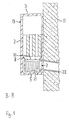
- FIG. 4 shows a schematic representation of a cross section along the section line BB of the attached to the outer wall 17 air exchange system 1 according to the embodiment.
- the cooling side of the plate heat exchanger 2 is considered.
- the interior of the housing 3 is divided into an upper exhaust air inlet area, a central plate heat exchanger area and a lower exhaust air outlet area.
- an exhaust air inlet opening 19 is provided on the front side of the housing 3.
- the plate heat exchanger region of the plate heat exchanger 2 is arranged, the four parallel, having vertically extending air ducts.
- the plate heat exchanger 2 shown here corresponds in principle to the plate heat exchanger 2 FIG. 2 , but has eight plates arranged one above the other.
- the exhaust air outlet area includes one in construction, in size, and in alignment with that in FIG FIG. 3 shown Zu Kunststofflutilizerrad 16 identical Fortllibraryllibraryerrad 21.
- the exhaust air fan 21 is centered within the exhaust fan housing 5 is arranged.
- an exhaust air outlet opening 7 At this exhaust air outlet 7 is an exhaust air outlet pipe 22, which extends slightly inclined to the right below. Centered on the top of the exhaust air fan housing 5, an exhaust air supply opening 20 is provided whose width corresponds to approximately one third of the total width of the exhaust air fan housing 5. Between the left and the right end of the underside of the plate heat exchanger 2 and the left and right sides of the top of the exhaust air fan housing 5, the hopper 8 is arranged.
- the exhaust air fan 6 and the exhaust air fan 21 sucks by the movement of the fan blades 23 at the same time to warm exhaust air from the building interior.
- This exhaust air flow 12 flows into the air ducts of the plate heat exchanger 2.
- the exhaust air stream 12 is cooled.
- the exhaust air stream 12 then passes through the funnel 8 and through the exhaust air supply opening 20 in the exhaust air fan housing 5.
- FIG. 5 shows a schematic plan view of a building section 23 with three attached to the inside of the outer wall 17 of this building section 23 air exchange devices 28, 29 and 30 according to a first embodiment.
- the building section 23 has a rectangular oblong shape and is divided into a first space 24, a second space 25, a third space 26 and a fourth space 27.
- the first space 24 has a rectangular shape, is located in the left quarter of the building section 23 and extends over the entire depth of the building section 23. The left, the front and the rear boundary of the first space 24 are formed by a portion of the outer wall 17. On the right side, the first space 24 is delimited by a straight partition wall, in whose front area a first door 241 is arranged, which connects the first space 24 with the fourth space 27.
- the fourth space 27 has a width of a good third of the total width of the building section 23 and a depth of approximately one third of the total depth of the building section 23.
- a portion of the outer wall 17 forms the front end of the fourth space 27.
- Behind the fourth space 27 is the second space 25, which is separated from the fourth space 27 by a straight partition.
- a second door 251 is arranged, which connects the fourth space 27 with the second space 25.
- Right outside the second space 25 and right of the fourth space 27 is the third space 26. It extends over the entire depth and over a third of the total width of the building portion 23.
- the third space 26 is defined by a straight partition of the second space 25 and separated from the fourth space 27, wherein in the front A third door 261 for connecting the third space 26 is arranged with the fourth space 27 of this partition wall.
- an entrance door 271 is provided which leads into the fourth room 27.
- a first air exchange device 28 is located in a left region of the rear wall of the first space 24.
- a second air exchange device 29 is provided in a right region of the rear wall of the second space 25.
- a third air exchange device 30 is disposed in a right portion of the rear wall of the third space 26.
- the air exchange devices 28 to 30 are each mounted with their back of the housing 3 to the inside of the outer wall 17.
- behind the air exchange devices 28 to 30 each extend an outside air supply pipe 18 and an exhaust air outlet pipe 22.
- the outside air supply pipes 18 are in FIG. 5 each shown in dashed lines.
- the air exchanging devices 28 to 30 are fixed to the outer wall 17 so that their outside air intake ports 4 abut respectively on the outside air supply pipe 18 and its exhaust air outlet port 7 on the exhaust air outlet pipe 22, respectively.
- the first air exchange device 28, the second air exchange device 29 and the third air exchange device 30 each promote a supply air flow 15 into the interior of the building section 23 and simultaneously promote a stream of exhaust air 13 from the interior of the building section 23 to the rear the building section 23 located outside of the building section 23rd
- the supply air fan 16 and the exhaust air fan 21 rotate at the same rotational frequency, so that the volume of the supply air 15 coincides with the volume of the exhaust air stream 13. With this mode of operation of the second air exchange device 29, a sufficient supply of the second space 25 is ensured with fresh heated outside air.
- the supply air impeller 16 of the first air exchange device 28 is operated at a 50% higher rotational frequency than the exhaust air impeller 21 of the first air exchange device 28.
- the funded by the first air exchange device 28 in the first space 24 supply air 15 is therefore greater by about 50% formed by the first air exchange device 28 more fresh supply air is conveyed into the first space 24, as spent exhaust air is conveyed out of it.
- the exhaust air impeller 21 of the third air exchange device 30 is operated at a rotational frequency that is 50% higher than the supply air impeller 16 of the third air exchange device 30. Accordingly, the volume of the exhaust air flow 13 conveyed out of the third space 26 is made larger by approximately 50% than that Volume of the supply air flow 15 conveyed from the outside of the building section 23 into the third space 26.
- the third air exchange device 28 thus conveys less fresh supply air into the third space 26, as spent exhaust air is transported out of him.
- FIG. 5 shown by arrows air movement between the first air exchange device 28 and the third air exchange device 30.
- the arrows that are in FIG. 5 between the second space 25 and the third space 26 do not pay attention.
- the result is an air flow which, starting from the first air exchange device 28, extends through the first space 24, through the fourth space 27 and through the third space 26 to the third air exchange device 30. This ensures that the first space 24 and the third space 26 and arranged between these two rooms fourth space 27 is supplied with fresh heated supply air.
- FIG. 5 a second variant of the second embodiment explained in which the first door 241, the second door 251 and the third door 261 are opened and the entrance door 271 are closed.
- both the first air exchange device 28 and the second air exchange device 29, the supply air impellers 16 each having a rotational frequency which is formed by about 25% higher than the rotational frequency of the exhaust air impellers 21. Accordingly, from the air exchange devices 28 and 29 respectively approximately 25% more supply air is conveyed into the interior of the building section 23, as outgoing air is conveyed out.
- the volume ratio of the supply air flow 15 to the exhaust air flow 13 in the case of the air exchange devices 28 and 29 is 55:45 in each case.
- the exhaust fan 21 of the third air exchange device 30 rotates at a rotational frequency which is greater by approximately 50%, than the rotational frequency of the supply air impeller 16 of the third air exchange device 30.
- the funded by the third air exchange device 30 in the third space 26 supply air 15 is therefore designed to be approximately 50% smaller than the simultaneously conveyed from the third space 26 to the outside of the building section 23 exhaust air stream 13.
- the ratio of the supply air flow 15 to the exhaust air stream 13 is approximately 40:60.
- This mode of operation of the air exchange devices 28-30 ensures supply of the rooms 24 to 27 with fresh, unused outside air.
- the fourth space 27 is vented, in which there is not directly an air exchange device.
- the air movement passes from the first air exchange device 28 through the first space 24, through the fourth space 27 and through the third space 26 to the third air exchange device 30 and from the second air exchange device 29 via the second space 25, over the fourth space 27 and over third space 26 to the third air exchange device 30.
- These air movements are in FIG. 5 represented by arrows.
- variants of the first embodiment can also larger building sections 23 with be ventilated the air exchange devices according to the invention.
- a far greater number of air exchange devices can be used, wherein an air exchange system with an even number of air exchange devices works very effectively.
Landscapes
- Engineering & Computer Science (AREA)
- Chemical & Material Sciences (AREA)
- Combustion & Propulsion (AREA)
- Mechanical Engineering (AREA)
- General Engineering & Computer Science (AREA)
- Physics & Mathematics (AREA)
- Fluid Mechanics (AREA)
- Ventilation (AREA)
- Building Environments (AREA)
- Central Air Conditioning (AREA)
Description
- Die Erfindung betrifft ein Luftaustauschsystem für die Belüftung wenigstens eines Raums eines Gebäudes mit wenigstens einer Luftaustauschvorrichtung.
- Zur Gewährleistung gleichbleibend hoher Atemluftqualität in Wohn- und Arbeitsräumen von Gebäuden wird oft ein Luftaustausch mit der Umwelt erzwungen. Dabei wird kühlere, unverbrauchte Außenluft in das Gebäudeinnere gefördert und gleichzeitig wärmere, verbrauchte Abluft aus dem Gebäudeinneren nach draußen gefördert. Aus Energieeffizienzgründen kann die Wärmeenergie der Abluft dazu verwendet werden, um die hineinströmende Außenluft zu erwärmen.
- Dabei kommen Wärmetauscher zum Einsatz, die Wärme in Richtung eines Temperaturgefälles zwischen den zwei Luftströmen übertragen. Es sind Rohrbündel-, Rippenrohr-, Platten-, Spiral-, Spiralrohr-Doppelmantel- und Wickelwärmetauscher bekannt. Solche Wärmetauscher sind häufig Bestandteile von Luftaustauschvorrichtungen, die auch als Rekuperatoren oder als Rekuperativgeräte bezeichnet werden.
- Die
WO 01/84057 A1 - Bei Gebäudeabschnitten mit mehreren Räumen, bei denen ein Luftaustausch mittelt einer dezentralen Luftaustauschvorrichtung mit einem Wärmetauscher vorgenommen wird, ergibt sich oft das Problem, daß dieser Luftaustausch nicht zufriedenstellend ist. Besonders diejenigen Räume, in denen sich die Luftaustauschvorrichtung nicht unmittelbar befindet, werden häufig nur unzureichend mit frischer und unverbrauchter Luft versorgt.
- Es ist daher Aufgabe der Erfindung, ein einfach handzuhabendes Luftaustauschsystem mit gutem Wirkungsgrad anzugeben, bei dem in allen zu belüftenden Räumen ein ausreichender Luftaustausch stattfindet.
- Diese Aufgabe wird durch den Gegenstand der unabhängigen Ansprüche gelöst. Vorteilhafte Ausgestaltungen ergeben sich aus den jeweiligen Unteransprüchen.
- Ein erfindungsgemäßes Luftaustauschsystem für die Belüftung wenigstens eines Raumes eines Gebäudes weist wenigstens zwei Luftaustauschvorrichtungen auf. Wenigstens eine von diesen Luftaustauschvorrichtungen beinhaltet ein Gehäuse, einen in dem Gehäuse angeordneten elektrischen Zuluft-Lüfter zur Förderung eines Zuluftstroms von einer Außenseite des Gebäudes in den bzw. in einen Raum des Gebäudes sowie einen in dem Gehäuse angeordneten Wärmetauscher. Das Luftaustauschsystem verfügt über wenigstens eine weitere Luftaustauschvorrichtung, die ein Gehäuse, einen in dem Gehäuse angeordneten elektrischen Fortluft-Lüfter zur Förderung eines Fortluftstroms aus dem bzw. aus einem Raum des Gebäudes auf die Außenseite des Gebäudes sowie einen in dem Gehäuse angeordneten Wärmetauscher aufweist. Durch die Abkühlseite der Wärmetauscher dieser Luftaustauschvorrichtungen fließt jeweils ein Fortluftstrom, durch die Erwärmseite der Wärmetauscher fließt jeweils ein Zuluftstrom.
- Gemäß einem Grundgedanken der Erfindung sorgt jede in dem Luftaustauschsystem vorgesehene Luftaustauschvorrichtung bereits für sich allein genommen für einen Abtransport von verbrauchter Fortluft sowie für ein Einströmen von frischer Zuluft. Gemäß einem weiteren Grundgedanken der Erfindung entsteht eine Luftbewegung zwischen derjenigen Luftaustauschvorrichtung, die lediglich einen Zuluft-Lüfter aufweist und derjenigen Luftaustauschvorrichtung, die lediglich einen Fortluft-Lüfter umfaßt. Diese Luftbewegung ist von der Luftaustauschvorrichtung mit dem Zuluft-Lüfter zu der Luftaustauschvorrichtung mit dem Fortluft-Lüfter gerichtet. Durch diese Luftbewegung wird sichergestellt, daß auch Bereiche, die nicht in unmittelbarer Nähe der Luftaustauschvorrichtungen liegen, mit frischer Außenluft versorgt werden.
- Durch ein derartiges Luftaustauschsystem wird ein zufriedenstellender Luftaustausch mit einem guten Wirkungsgrad erreicht.
- Ein weiteres erfindungsgemäßes Luftaustauschsystem für die Belüftung wenigstens eines Raumes eines Gebäudes verfügt über wenigstens zwei Luftaustauschvorrichtungen der folgenden Art. Die Luftaustauschvorrichtung gliedert sich in ein Gehäuse, in einen in dem Gehäuse angeordneten elektrischen Zuluft-Lüfter zur Förderung eines Zuluftstroms von einer Außenseite des Gebäudes in den bzw. in einen Raum des Gebäudes, in einen weiteren in dem Gehäuse angeordneten elektrischen Fortluft-Lüfter zur Förderung eines Fortluftstroms aus dem bzw. aus einem Raum des Gebäudes auf die Außenseite des Gebäudes sowie in einen in dem Gehäuse angeordneten Wärmetauscher, durch dessen Erwärmseite der Zuluftstrom und durch dessen Abkühlseite der Abluftstrom fließt.
- Ein Grundgedanke bei diesem erfindungsgemäßen Luftaustauschsystem besteht darin, daß bei wenigstens einer Luftaustauschvorrichtung der Zuluft-Lüfter und der Fortluft-Lüfter so einstellbar sind, daß der Zuluftstrom größer als der Fortluftstrom ausgebildet ist und daß bei wenigstens einer weiteren Luftaustauschvorrichtung der Zuluft-Lüfter und der Fortluft-Lüfter so einstellbar sind, daß der Fortluftstrom größer als der Zuluftstrom ausgebildet ist. Durch eine derartige Einstellbarkeit der Volumenströme der durch den Zuluft-Lüfter und durch den Fortluft-Lüfter geförderten Luftmengen kann der Luftaustausch der einzelnen Luftaustauschvorrichtungen und somit der Luftaustausch des Luftaustauschsystems individuell an die Umgebung angepaßt werden. Zusätzlich zu demjenigen Luftaustausch, den jede Luftaustauschvorrichtung für sich allein gesehen tätigt, wird eine Luftbewegung zwischen den einzelnen Luftaustauschvorrichtungen erzeugt. Dadurch wird ein Luftaustausch auch in denjenigen Bereichen sichergestellt, die sich nicht in unmittelbarer Umgebung einer der Luftaustauschvorrichtungen befinden.
- Die Intensität der Luftbewegung zwischen den einzelnen Luftaustauschvorrichtungen kann durch eine Veränderung der Drehfrequenzen der Lüfter und/oder der Anstellwinkel der Lüfterblätter genau und bedarfsgerecht eingestellt werden.
- Bei einer einfachen Version des erfindungsgemäßen Luftaustauschsystems, die zwei Luftaustauschvorrichtungen umfaßt, kann die erste Luftaustauschvorrichtung beispielsweise mit einem Verhältnis des Fortluftstromvolumens zum Zuluftstromvolumen von 40%/60% und die zweite Luftaustauschvorrichtung beispielsweise mit einem Verhältnis des Fortluftstromvolumens zum Zuluftstromvolumen von 60%/40% betrieben werden. Eine Richtungsänderung der Luftbewegung zwischen den Luftaustauschvorrichtungen kann dadurch erreicht werden, indem das Verhältnis des Fortluftstromvolumens zu dem Zuluftstromvolumen bei beiden Luftaustauschvorrichtungen umgekehrt wird.
- Von der Erfindung sind auch Luftaustauschsysteme umfaßt, die drei oder mehr Luftaustauschvorrichtungen aufweisen. Solche Luftaustauschsysteme werden auch als Netzwerkversionen bezeichnet.
- Die Erfindung betrifft auch ein vorstehend beschriebenes Luftaustauschsystem mit wenigstens einer Außenwand des Gebäudes. Dabei sind die Gehäuserückseiten der Luftaustauschvorrichtungen an wenigstens einer Außenwand des Gebäudes angebracht. An bzw. in der Außenwand sind Rohrverbindungen vorgesehen, die sich bis zu der Außenseite des Gebäudes erstrecken. Über diese Rohrverbindungen kann frische unverbrauchte Außenluft in die Luftaustauschvorrichtungen hinein und verbrauchte Fortluft aus den Luftaustauschvorrichtungen auf die Außenseite des Gebäudes gelangen. Mit derart angebrachten Luftaustauschvorrichtungen wird ein direkter und effektiver Luftaustausch der verbrauchten Abluft mit frischer Außenluft erreicht.
- Gemäß einer ersten Ausführungsform der Erfindung ist wenigstens eine Luftaustauschvorrichtung an einer ersten Außenwand und wenigstens eine weitere Luftaustauschvorrichtung an einer zweiten Außenwand angebracht. Wenn diese beiden Wände einander gegenüberliegen, so wird der zwischen den beiden Wänden liegende Gebäudeabschnitt kontinuierlich mit frischer und erwärmter Zuluft versorgt.
- Befinden sich die erste Außenwand sowie die zweite Außenwand in unterschiedlichen Räumen des Gebäudes, so werden die zwischen den beiden Außenwänden liegenden Räume des Gebäudes ebenfalls kontinuierlich mit frischer erwärmter Außenluft durchspült. Hierbei ist sicherzustellen, daß die Luftbewegung zwischen diesen Räumen nicht beispielsweise durch eine geschlossene Tür unterbrochen wird.
- Wenn zwischen der ersten Außenwand und der zweiten Außenwand wenigstens ein Durchgang, insbesondere eine Treppe, eine Tür oder ein Korridor und/oder wenigstens ein weiterer Raum angeordnet ist, so werden diese ebenfalls kontinuierlich mit frischer erwärmter Außenluft versorgt. Dies wird auch als Querlüftung bezeichnet.
- In einer vorteilhaften Weiterbildung der Erfindung sind die Luftaustauschvorrichtungen mit einer Steuerungseinheit, insbesondere mit einem Computer, verbunden. Über diese Steuerungseinheit können die Drehfrequenzen der Lüfterräder und/oder die Anstellwinkel der Lüfterblätter für die Zuluft-Lüfter und für die Fortluft-Lüfter der einzelnen Luftaustauschvorrichtungen individuell und präzise eingestellt werden.
- Die Erfindung ist in den Zeichnungen anhand eines Ausführungsbeispiels näher veranschaulicht.
- Figur 1
- zeigt eine schematische Darstellung einer Draufsicht auf eine Luftaustauschvorrichtung gemäß einem Ausführungsbeispiel,
- Figur 2
- zeigt eine schematische, perspektivische Darstellung des in
Figur 1 gezeigten Plattenwärmetauschers sowie eine grafische Veranschaulichung der den Plattenwärmetauscher durchfließenden Luftströme gemäß dem Ausführungsbeispiel, - Figur 3
- zeigt eine schematische Darstellung eines Querschnitts entlang der Schnittlinie A-A einer an einer Außenwand befestigten Luftaustauschvorrichtung gemäß dem Ausführungsbeispiel,
- Figur 4
- zeigt eine schematische Darstellung eines Querschnitts entlang der Schnittlinie B-B der an der Außenwand befestigten Luftaustauschvorrichtung gemäß dem Ausführungsbeispiel, und
- Figur 5
- zeigt einen schematischen Grundriß eines Gebäudeabschnitts mit drei an der Innenseite einer Außenwand dieses Gebäudeabschnitts befestigten in
Figur 1 gezeigten Luftaustauschvorrichtungen gemäß einem ersten Ausführungsbeispiel. -
Figur 1 zeigt eine schematische Darstellung einer Draufsicht auf eine Luftaustauschvorrichtung 1 gemäß einem Ausführungsbeispiel. - Die Luftaustauschvorrichtung 1 ist von einem quadratischen Gehäuse 3 umschlossen. Bei der in
Figur 1 gezeigten Draufsicht ist die Vorderseite des Gehäuses 3 abgenommen. Das Gehäuse 3 weist im Ausführungsbeispiel Kunststoff auf, ist aber auch aus anderen Materialien fertigbar. - Mittig in dem Gehäuse 3 ist ein quadratischer Plattenwärmetauscher 2 angeordnet, insbesondere aus gut wärmeleitendem Metall, wobei in der Draufsicht gemäß
Figur 1 nur die oberste Platte des Plattenwärmetauschers 2 sichtbar ist. Die Seitenlänge des Plattenwärmetauschers 2 entspricht knapp der Hälfte der Seitenlänge des Gehäuses 3. Der Plattenwärmetauscher 2 ist in einem Winkel von 45° bezogen auf das Gehäuse 3 gedreht angeordnet. - Oberhalb der rechten oberen Seite des Plattenwärmetauschers 2 ist eine kreisrunde Außenlufteinlaßöffnung 4 in der Unterseite des Gehäuses 3 vorgesehen. Um die Außenlufteinläßöffnung 4 ist eine auf der Unterseite des Gehäuses 3 aufsetzende, gekrümmte Wand vorgesehen, die am oberen sowie am unteren Ende der rechten oberen Seite des Plattenwärmetauschers 2 abschließt.
- Auf der linken oberen Seite des Plattenwärmetauschers 2 ist eine ähnlich geformte Wand vorgesehen, die am oberen sowie am unteren Ende der linken oberen Seite des Plattenwärmetauschers 2 abschließt. In der hier nicht gezeigten Vorderseite des Gehäuses 3 ist eine Öffnung vorgesehen, die beim Aufsetzen der Vorderseite auf das Gehäuse 3 innerhalb dieser Wand angeordnet ist.
- An der rechten unteren Seite des Plattenwärmetauschers 2 ist ein Fortluft-Lüftergehäuse 5 mit einem Fortluftradiallüfter 6 sowie ein zwischen dem Fortluftradiallüfter 6 und dem Plattenwärmetauscher 2 angeordneter Trichter 8 vorgesehen. Der Trichter 8 setzt auf der gesamten Breite der rechten unteren Seite des Plattenwärmetauschers 2 an und verjüngt sich auf einer Strecke etwa einem Achtel der Seitenlänge des Plattenwärmetauschers 2 um einen Winkel von 30°. Auf der gesamten Breite des Auslaßseite des Trichters 8 setzt der Fortluftradiallüfter 6 an, von dem in der Draufsicht in
Figur 1 lediglich die Verkleidung erkennbar ist. Die Drehachse des Fortluftradiallüfters 6 ist dabei senkrecht auf der Höhe der Mitte der rechten unteren Seite des Plattenwärmetauschers 2 ausgerichtet. Der Durchmesser bzw. die Breite des Fortluftradiallüfters 6 entspricht dabei in etwa der Auslaßseite des Trichters 8. Die Tiefe des Fortluftradiallüfters 6 entspricht ungefähr der Hälfte seiner Breite. Der Fortluftradiallüfter 6 ist von einem Fortluft-Lüftergehäuse 5 umschlossen, das auf seiner Unterseite eine inFigur 1 gestrichelt dargestellte, rechteckige Fortluftauslaßöffnung 7 aufweist. Diese Fortluftauslaßöffnung 7 ist dabei von der Mitte des Fortluftradiallüfters 6 ausgehend etwas nach rechts oben versetzt angeordnet. - An der linken unteren Seite des Plattenwärmetauschers 2 setzt ein von einem dünnwandigen Zuluft-Lüftergehäuse 9 umschlossener Zuluftansaugradiallüfter 10 an. Dabei ist die Drehachse des Zuluftansaugradiallüfters 10 orthogonal zu der linken unteren Seite des Plattenwärmetauschers 2 auf der Höhe deren Mitte angeordnet. Der Durchmesser bzw. die Breite des Zulaufansaugradiallüfters 10 entspricht in etwa der Seitenlänge des Plattenwärmetauschers 2, seine Tiefe entspricht ungefähr der Hälfte seiner Breite. In dem linken oberen Bereich des Zuluftansaugradiallüfters 10 ist eine rechteckige Zulufteinlaßöffnung angeordnet, durch die mehrere Lüfterschaufeln des Zuluftansaugradiallüfters 10 erkennbar sind. Diese sind im Ausführungsbeispiel parallel zur Drehachse des Zuluftansaugradiallüfters 10 angeordnet, können jedoch auch schräg zu dieser oder gekrümmt verlaufen.
- Ein erste Schnittlinie A-A verläuft durch die linke untere sowie durch die rechte obere Ecke des Gehäuses 3. Eine weitere Schnittlinie B-B verläuft durch die linke obere sowie durch die rechte untere Ecke des Gehäuses 3.
-
Figur 2 zeigt eine schematische, perspektivische Darstellung des inFigur 1 gezeigten Plattenwärmetauschers 2 sowie eine grafische Veranschaulichung der den Plattenwärmetauscher 2 durchfließenden Luftströme gemäß dem Ausführungsbeispiel. - Der Plattenwärmetauscher 2 umfaßt drei übereinander angeordnete, quadratische Metallplatten, die in
Figur 2 jeweils auf einer Ecke stehend dargestellt sind. Die untere und die mittlere Platte des Plattenwärmetauschers 2 weisen auf der linken oberen Seite einen schlitzartigen Warmlufteinlaß 102 und auf der rechten unteren Seite einen schlitzartigen Kaltluftauslaß 103 auf. Auf der linken unteren sowie auf der rechten oberen Seite ist die untere Platte mit der mittleren Platte des Plattenwärmetauschers 2 jeweils mit einer durchgehenden Wand verbunden. An der rechten oberen Seite des Plattenwärmetauschers 2 befindet sich zwischen der mittleren und der oberen Platte ein schlitzartiger Kaltlufteinlaß 104. An der linken unteren Seite des Plattenwärmetauschers 2 ist zwischen der mittleren und der oberen Platte des Plattenwärmetauschers 2 ein schlitzartiger Warmluftauslaß 105 vorgesehen. An der linken oberen sowie an der rechten unteren Seite des Plattenwärmetauschers 2 ist zwischen der mittleren und der oberen Platte jeweils eine Wand vorgesehen. - Gemäß der Darstellung in
Figur 2 fließt ein Abluftstrom 12 in den Warmlufteinlaß 102 hinein, durchströmt den Plattenwärmetauscher 2 und tritt auf der gegenüberliegenden Seite als Fortluftstrom 13 aus dem Kaltluftauslaß 103 aus. Der dabei von dem Abluftstrom 12 durchflossene Bereich des Plattenwärmetauschers 2 wird auch als Abkühlseite bezeichnet. Ein Außenluftstrom 14 tritt durch den Kaltlufteinlaß 104 in den Plattenwärmetauscher 2 ein, durchströmt diesen und tritt als Zuluftstrom 15 auf der gegenüberliegenden Seite aus dem Warmluftauslaß 105 aus. Der dabei von dem Außenluftstrom 14 durchflossenen Bereich des Plattenwärmetauschers 2 wird auch Erwärmseite des Plattenwärmetauschers 2 genannt. -
Figur 3 zeigt eine schematische Darstellung eines Querschnitts entlang der Schnittlinie A-A einer an einer Außenwand 17 befestigten Luftaustauschvorrichtung 1 gemäß dem Ausführungsbeispiel. InFigur 3 ist die Erwärmseite des Plattenwärmetauschers 2 betrachtet. - Die Luftaustauschvorrichtung 1 liegt mit der Rückseite ihres. Gehäuses 3 an der Vorderseite der Außenwand 17 an und befindet sich dementsprechend im Gebäudeinneren. Aus der Querschnittsdarstellung in
Figur 3 ist ersichtlich, daß die diagonale Höhe des Luftaustauschsystems 1 in etwa dem Dreifachen seiner Tiefe entspricht. Dabei gliedert sich das Innere des Gehäuses 3 in einen zuoberst angeordneten Außenlufteinlaßbereich, in einen mittig angeordneten Plattenwärmetauscherbereich und in einen zuunterst angeordneten Zuluftauslaßbereich. - In dem Außenlufteinlaßbereich ist an der Rückseite des Gehäuses 3 die Außenlufteinlaßöffnung 4 ausgebildet, an die sich außenwandseitig ein waagerechtes Außenluftzufuhrrohr 18 anschließt. In dem Plattenwärmetauscherbereich ist der Plattenwärmetauscher 2 angeordnet, der drei parallele, in der Darstellung gemäß
Figur 3 von oben nach unten verlaufende Luftführungen aufweist. Der hier gezeigte Plattenwärmetauscher 2 entspricht prinzipiell dem Plattenwärmetauscher 2 ausFigur 2 , weist jedoch acht übereinander angeordnete Platten auf. In dem Zuluftauslaßbereich ist ein Zuluft-Lüfterrad 16 innerhalb des Zuluft-Lüftergehäuses 9 angeordnet. Das Zuluft-Lüfterrad 16 ist dabei horizontal mittig angeordnet. Auf gleicher Höhe mit den Lüfterschaufeln des Zuluft-Lüfterrads 16 ist in der Vorderseite des Gehäuses 3 sowie in der linken Seite des Zuluft-Lüftergehäuses 9 eine Zuluftauslaßöffnung 11 vorgesehen, deren Höhe der Breite der Lüfterschaufeln entspricht. - Das Zuluft-Lüftergehäuse setzt auf dem linken sowie auf dem rechten Ende der Unterseite des Plattenwärmetauschers 2 an, verläuft beidseitig vertikal nach unten und weist unmittelbar vor der Unterseite des Gehäuses 3 eine waagerechte Unterseite auf.
-
Figur 4 zeigt eine schematische Darstellung eines Querschnitts entlang der Schnittlinie B-B des an der Außenwand 17 befestigten Luftaustauschsystems 1 gemäß dem Ausführungsbeispiel. InFigur 4 ist die Abkühlseite des Plattenwärmetauschers 2 betrachtet. - Das Innere des Gehäuses 3 gliedert sich dabei in einen oberen Ablufteinlaßbereich, in einen mittleren Plattenwärmetauscherbereich und in einen unteren Fortluftauslaßbereich. Im Ablufteinlaßbereich ist auf der Vorderseite des Gehäuses 3 eine Ablufteinlaßöffnung 19 vorgesehen. Im Plattenwärmetauscherbereich ist der Plattenwärmetauscher 2 angeordnet, der vier parallele, vertikal verlaufende Luftführungen aufweist. Der hier gezeigte Plattenwärmetauscher 2 entspricht prinzipiell dem Plattenwärmetauscher 2 aus
Figur 2 , weist jedoch acht übereinander angeordnete Platten auf. Der Fortluftauslaßbereich umfaßt einen hinsichtlich der Bauart, hinsichtlich der Größe und hinsichtlich der Ausrichtung mit dem inFigur 3 gezeigten Zuluftlüfterrad 16 identisches Fortlüftlüfterrad 21. Das Fortluft-Lüfterrad 21 ist zentriert innerhalb des Fortluft-Lüftergehäuses 5 angeordnet. Horizontal auf gleicher Höhe mit dem Fortluft-Lüfterrad 21 weist das Fortluft-Lüftergehäuse 5 auf der rechten Seite sowie das Gehäuse 3 auf seiner Rückseite jeweils eine Fortluftauslaßöffnung 7 auf. An dieser Fortluftauslaßöffnung 7 setzt ein Fortluftauslaßrohr 22 an, das leicht nach rechts unten geneigt verläuft. Mittig auf der Oberseite des Fortluft-Lüftergehäuses 5 ist eine Fortluftzuführungsöffnung 20 vorgesehen, deren Breite ungefähr einem Drittel der Gesamtbreite des Fortluft-Lüftergehäuses 5 entspricht. Zwischen dem linken und dem rechten Ende der Unterseite des Plattenwärmetauschers 2 und der linken und rechten Seite der Oberseite des Fortluft-Lüftergehäuses 5 ist der Trichter 8 angeordnet. - Im folgenden wird die Funktionsweise der Luftaustauschvorrichtung 1 näher erläutert.
- Wie in
Figur 2 beschrieben, besteht zwischen dem Abluftstrom 12 und dem Außenluftstrom 14 ein Temperaturgefälle, das im Betrieb der Luftaustauschvorrichtung 1 durch den Plattenwärmetauscher 2 reduziert wird. Dabei wird der Abluftstrom 12 abgekühlt und der Außenluftstrom 14 erwärmt. Der Abluftstrom 12 sondert bei der Abkühlung Kondenswasser ab, das an der Abkühlseite des Plattenwärmetauschers 2, insbesondere an dem Kaltluftauslaß 103 auftritt. - Wie in
Figur 1 sowie inFigur 3 dargestellt, wird durch den Zuluftansaugradiallüfter 10 bzw. durch das Zuluftlüfterrad 16 kalte Außenluft angesaugt. Dieser Außenluftstrom 14 tritt durch das inFigur 3 gezeigte Außenluftzufuhrrohr 18 in die Luftaustauschvorrichtung 1 ein. Dann strömt der Außenluftstrom 14 durch die Luftführungen des Plattenwärmetauschers 2 und wird dabei erwärmt. Anschließend fließt die nun als Zuluftstrom 15 bezeichnete, erwärmte Luft durch die Zuluftauslaßöffnung 11 auf der Gehäusevorderseite 26 in das Gebäudeinnere. - Wie in
Figur 1 und inFigur 4 ersichtlich, saugt der Fortluftradiallüfter 6 bzw. das Fortluft-Lüfterrad 21 durch die Bewegung der Lüfterschaufeln 23 gleichzeitig dazu warme Abluft aus dem Gebäudeinneren an. Dieser Abluftstrom 12 fließt in die Luftführungen des Plattenwärmetauschers 2. Beim Durchströmen des Plattenwärmetauschers 2 wird der Abluftstrom 12 gekühlt. Der Abluftstrom 12 gelangt danach durch den Trichter 8 und durch die Fortluftzuführungsöffnung 20 in das Fortluft-Lüftergehäuse 5. Von dort aus wird die nun als Fortluftstrom 13 bezeichnete Luft - in Folge der Bewegung des Fortluft-Lüfterrads 21 sowie in Folge der Druckdifferenz, die zwischen dem Innenraum des Fortluft-Lüfterrads 21 und dem außerhalb der Fortluftauslaßöffnung 7 gelegenen Bereich herrscht - durch die Fortluftauslaßöffnung 7 aus der Luftaustauschvorrichtung 1 sowie durch das Fortluftauslaßrohr 22 auf eine Außenseite des Gebäudes befördert. -
Figur 5 zeigt einen schematischen Grundriß eines Gebäudeabschnitts 23 mit drei an der Innenseite der Außenwand 17 dieses Gebäudeabschnitts 23 befestigten Luftaustauschvorrichtungen 28, 29 und 30 gemäß einem ersten Ausführungsbeispiel. - Der Gebäudeabschnitt 23 weist eine rechteckige längliche Form auf und gliedert sich in einen ersten Raum 24, in einen zweiten Raum 25, in einen dritten Raum 26 sowie in einen vierten Raum 27. Der erste Raum 24 weist eine rechteckige Form auf, befindet sich in dem linken Viertel des Gebäudeabschnitts 23 und erstreckt sich über die gesamte Tiefe des Gebäudeabschnitts 23. Die linke, die vordere und die hintere Begrenzung des ersten Raums 24 werden von einem Abschnitt der Außenwand 17 gebildet. Auf der rechten Seite wird der erste Raum 24 von einer gerade verlaufenden Zwischenwand begrenzt, in deren vorderem Bereich eine erste Tür 241 angeordnet ist, die den ersten Raum 24 mit dem vierten Raum 27 verbindet. Der vierte Raum 27 weist eine Breite von einem guten Drittel der Gesamtbreite des Gebäudeabschnitts 23 und eine Tiefe von ungefähr einem Drittel der Gesamttiefe des Gebäudeabschnitts 23 auf. Ein Abschnitt der Außenwand 17 bildet das vordere Ende des vierten Raums 27. Hinter dem vierten Raum 27 befindet sich der zweite Raum 25, der von dem vierten Raum 27 durch eine gerade verlaufende Zwischenwand getrennt ist. In dem rechten Bereich dieser Zwischenwand ist eine zweite Tür 251 angeordnet, die den vierten Raum 27 mit dem zweiten Raum 25 verbindet. Rechterhalb des zweiten Raums 25 und rechterhalb des vierten Raums 27 befindet sich der dritte Raum 26. Dieser erstreckt sich über die gesamte Tiefe und über ein gutes Drittel der Gesamtbreite des Gebäudeabschnitts 23. Der dritte Raum 26 ist durch eine gerade verlaufende Zwischenwand von dem zweiten Raum 25 und von dem vierten Raum 27 getrennt, wobei in dem vorderen Bereich dieser Zwischenwand eine dritte Tür 261 zur Verbindung des dritten Raums 26 mit dem vierten Raum 27 angeordnet ist. An der Vorderseite des Gebäudeabschnitts 23 ist eine Eingangstür 271 vorgesehen, die in den vierten Raum 27 führt.
- Eine erste Luftaustauschvorrichtung 28 befindet sich in einem linken Bereich der hinteren Wand des ersten Raums 24. Eine zweite Luftaustauschvorrichtung 29 ist in einem rechten Bereich der hinteren Wand des zweiten Raums 25 vorgesehen. Eine dritte Luftaustauschvorrichtung 30 ist in einem rechten Bereich der hinteren Wand des dritten Raums 26 angeordnet. Die Luftaustauschvorrichtungen 28 bis 30 sind jeweils mit ihrer Rückseite des Gehäuses 3 an die Innenseite der Außenwand 17 montiert. Dabei verlaufen hinter den Luftaustauschvorrichtungen 28 bis 30 jeweils ein Außenluftzufuhrrohr 18 sowie ein Fortluftauslaßrohr 22. Die Außenluftzufuhrrohre 18 sind in
Figur 5 jeweils gestrichelt dargestellt. Die Luftaustauschvorrichtungen 28 bis 30 sind so an der Außenwand 17 befestigt, daß ihre Außenlufteinlaßöffnung 4 jeweils auf dem Außenluftzufuhrrohr 18 und ihre Fortluftauslaßöffnung 7 jeweils auf dem Fortluftauslaßrohr 22 anliegen. - Nachfolgend wird mit Bezug auf
Figur 5 zunächst eine erste Variante des ersten Ausführungsbeispiels beschrieben, bei dem die zweite Tür 251 und die Eingangstür 271 geschlossen und die erste Tür 241 sowie die dritte Tür 261 geöffnet sind. - Die erste Luftaustauschvorrichtung 28, die zweite Luftaustauschvorrichtung 29 sowie die dritte Luftaustauschvorrichtung 30 fördern jeweils einen Zuluftstrom 15 in das Innere des Gebäudeabschnitts 23 und fördern gleichzeitig einen Fortluftstrom 13 aus dem Inneren des Gebäudeabschnitts 23 auf die hinter dem Gebäudeabschnitt 23 gelegene Außenseite des Gebäudeabschnitts 23.
- Bei der zweiten Luftaustauschvorrichtung 29 drehen sich das Zuluft-Lüfterrad 16 und das Fortluft-Lüfterrad 21 mit derselben Drehfrequenz, so daß das Volumen des Zuluftstroms 15 mit dem Volumen des Fortluftstroms 13 übereinstimmt. Mit diesem Betriebsmodus der zweiten Luftaustauschvorrichtung 29 wird eine ausreichende Versorgung des zweiten Raums 25 mit frischer erwärmter Außenluft sichergestellt.
- Das Zuluft-Lüfterrad 16 der ersten Luftaustauschvorrichtung 28 wird mit einer um 50% höheren Drehfrequenz betrieben als das Fortluft-Lüfterrad 21 der ersten Luftaustauschvorrichtung 28. Der durch die erste Luftaustauschvorrichtung 28 in den ersten Raum 24 geförderte Zuluftstrom 15 ist demnach um ungefähr 50% größer ausgebildet als der aus dem ersten Raum 24 auf die Außenseite des Gebäudeabschnitts 23 geförderte Fortluftstrom 13. Durch die erste Luftaustauschvorrichtung 28 wird demnach mehr frische Zuluft in den ersten Raum 24 befördert, als verbrauchte Fortluft aus ihm hinausbefördert wird.
- Das Fortluft-Lüfterrad 21 der dritten Luftaustauschvorrichtung 30 wird mit einer um 50% höheren Drehfrequenz betrieben als das Zuluft-Lüfterrad 16 der dritten Luftaustauschvorrichtung 30. Dementsprechend ist das Volumen des aus dem dritten Raum 26 herausbeförderten Fortluftstroms 13 um ungefähr 50% größer ausgebildet als das Volumen des von der Außenseite des Gebäudeabschnitts 23 in den dritten Raum 26 hineinbeförderten Zuluftstroms 15. Durch die dritte Luftaustauschvorrichtung 28 wird somit weniger frische Zuluft in den dritten Raum 26 befördert, als verbrauchte Fortluft aus ihm hinausbefördert wird.
- In dem Gebäudeabschnitt 23 entwickelt sich eine in
Figur 5 mittels Pfeilen dargestellte Luftbewegung zwischen der ersten Luftaustauschvorrichtung 28 und der dritten Luftaustauschvorrichtung 30. Dabei sind die Pfeile, die inFigur 5 zwischen dem zweiten Raum 25 und dem dritten Raum 26 verlaufen, nicht zu beachten. Es entsteht ein Luftstrom, der sich, ausgehend von der ersten Luftaustauschvorrichtung 28, durch den ersten Raum 24, durch den vierten Raum 27 und durch den dritten Raum 26 bis zu der dritten Luftaustauschvorrichtung 30 erstreckt. Dadurch ist gewährleistet, daß der erste Raum 24 und der dritte Raum 26 sowie der zwischen diesen beiden Räumen angeordnete vierte Raum 27 mit frischer erwärmter Zuluft versorgt wird. - Im folgenden wird mit Bezug auf
Figur 5 eine zweite Variante des zweiten Ausführungsbeispiels erläutert, bei dem die erste Tür 241, die zweite Tür 251 und die dritte Tür 261 geöffnet und die Eingangstür 271 geschlossen sind. - Dabei arbeiten sowohl bei der ersten Luftaustauschvorrichtung 28 sowie bei der zweiten Luftaustauschvorrichtung 29 die Zuluft-Lüfterräder 16 jeweils mit einer Drehfrequenz, die um ungefähr 25% höher ausgebildet ist als die Drehfrequenz der Fortluft-Lüfterräder 21. Dementsprechend wird von den Luftaustauschvorrichtungen 28 und 29 jeweils ungefähr 25% mehr Zuluft in das Innere des Gebäudeabschnitts 23 befördert, als Abluft hinausbefördert wird. Das Volumenverhältnis des Zuluftstroms 15 zu dem Fortluftstrom 13 beträgt bei den Luftaustauschvorrichtungen 28 und 29 jeweils 55:45.
- Das Fortluft-Lüfterrad 21 der dritten Luftaustauschvorrichtung 30 dreht sich mit einer Drehfrequenz, die um ca. 50% größer ist, als die Drehfrequenz des Zuluft-Lüfterrads 16 der dritten Luftaustauschvorrichtung 30. Der von der dritten Luftaustauschvorrichtung 30 in den dritten Raum 26 geförderte Zuluftstrom 15 ist daher um ca. 50% geringer ausgebildet als der gleichzeitig aus dem dritten Raum 26 auf die Außenseite des Gebäudeabschnitts 23 beförderte Fortluftstrom 13. Das Verhältnis des Zuluftstroms 15 zu dem Fortluftstrom 13 beträgt ungefähr 40:60.
- Durch diesen Betriebsmodus der Luftaustauschvorrichtungen 28-30 wird eine Versorgung der Räume 24 bis 27 mit frischer unverbrauchter Außenluft gewährleistet. Dabei wird auch der vierte Raum 27 durchlüftet, in dem sich nicht unmittelbar eine Luftaustauschvorrichtung befindet. Die Luftbewegung verläuft von der ersten Luftaustauschvorrichtung 28 durch den ersten Raum 24, durch den vierten Raum 27 und durch den dritten Raum 26 zu der dritten Luftaustauschvorrichtung 30 sowie von der zweiten Luftaustauschvorrichtung 29 über den zweiten Raum 25, über den vierten Raum 27 und über den dritten Raum 26 zu der dritten Luftaustauschvorrichtung 30. Diese Luftbewegungen sind in
Figur 5 mittels Pfeilen dargestellt. - Diese Luftbewegungen können sehr einfach modifiziert werden, indem die Drehfrequenzen der Zuluft-Lüfterräder 16 sowie der Fortluft-Lüfterräder 21 der Luftaustauschvorrichtungen 28-30 verändert werden.
- In weiteren, hier nicht gezeigten Varianten des ersten Ausführungsbeispiels können auch größere Gebäudeabschnitte 23 mit den erfindungsgemäßen Luftaustauschvorrichtungen belüftet werden. Dabei kann auch eine weit größere Zahl von Luftaustauschvorrichtungen zum Einsatz kommen, wobei ein Luftaustauschsystem mit einer geraden Anzahl von Luftaustauschvorrichtungen besonders effektiv arbeitet.
-
- 1
- Luftaustauschvorrichtung
- 2
- Plattenwärmetauscher
- 3
- Gehäuse
- 4
- Außenlufteinlaßöffnung
- 5
- Fortluft-Lüftergehäuse
- 6
- Fortluftradiallüfter
- 7
- Fortluftauslaßöffnung
- 8
- Trichter
- 9
- Zuluft-Lüftergehäuse
- 10
- Zuluftansaugradiallüfter
- 11
- Zuluftauslaßöffnung
- 12
- Abluftstrom
- 13
- Fortluftstrom
- 14
- Außenluftstrom
- 15
- Zuluftstrom
- 102
- Warmlufteinlaß
- 103
- Kaltluftauslaß
- 104
- Kaltlufteinlaß
- 105
- Warmluftauslaß
- 16
- Zuluft-Lüfterrad
- 17
- Außenwand
- 18
- Außenluftzufuhrrohr
- 19
- Ablufteinlaßöffnung
- 20
- Fortluftzuführungsöffnung
- 21
- Fortluft-Lüfterrad
- 22
- Fortluftauslaßrohr
- 23
- Gebäudeabschnitt
- 24
- erster Raum
- 241
- erste Tür
- 25
- zweiter Raum
- 251
- zweite Tür
- 26
- dritter Raum
- 261
- dritte Tür
- 27
- vierter Raum
- 271
- Eingangstür
- 28
- erste Luftaustauschvorrichtung
- 29
- zweite Luftaustauschvorrichtung
- 30
- dritte Luftaustauschvorrichtung
Claims (8)
- Luftaustauschsystem für die Belüftung wenigstens eines Raums (24-27) eines Gebäudes (23) mit wenigstens zwei Luftaustauschvorrichtungen (28-30), die jeweils die folgenden Merkmale aufweisen:- ein Gehäuse (3),- ein in dem Gehäuse (3) angeordneter elektrischer Zuluft-Lüfter (16) zur Förderung eines Zuluftstroms (15),- ein weiterer in dem Gehäuse (3) angeordneter elektrischer Fortluft-Lüfter (21) zur Förderung eines Fortluftstroms (13),- ein in dem Gehäuse (3) angeordneter Wärmetauscher (2), durch dessen Erwärmseite der Zuluftstrom (15) und durch dessen Abkühlseite der Fortluftstrom (13) fließt,wobei das Luftaustauschsystem zum Erzeugen einer Luftbewegung zwischen wenigstens einer Luftaustauschvorrichtung und wenigstens einer weiteren Luftaustauschvorrichtung derart ausgebildet ist, dass bei der einen Luftaustauschvorrichtung (28,29) der Zuluft-Lüfter (16) und der Fortluft-Lüfter (21) so eingestellt sind, dass der Zuluftstrom (15) größer als der Fortluftstrom (13) ausgebildet ist, und
dass bei der weiteren Luftaustauschvorrichtung (30) der Zuluft-Lüfter (16) und der Fortluft-Lüfter (21) so eingestellt sind, dass der Fortluftstrom (13) größer als der Zuluftstrom (15) ausgebildet ist. - Luftaustauschsystem nach Anspruch 1 mit wenigstens einer Außenwand (17) des Gebäudes (23),
dadurch gekennzeichnet, daß
die Gehäuserückseiten der Luftaustauschvorrichtungen (28-30) an wenigstens einer Außenwand (17) angebracht sind und daß an bzw. in der Außenwand (17) wenigstens eine Rohrverbindung (18,22) zu der Außenseite des Gebäudes (23) vorgesehen ist. - Luftaustauschsystem nach Anspruch 2,
dadurch gekennzeichnet, daß
wenigstens eine Luftaustauschvorrichtung (28-30) an einer ersten Außenwand und wenigstens eine weitere Luftaustauschvorrichtung (28-30) an einer insbesondere gegenüber der ersten Außenwand liegenden zweiten Außenwand angebracht sind. - Luftaustauschsystem nach Anspruch 3,
dadurch gekennzeichnet, daß
sich die erste Außenwand (17) und die zweite Außenwand (17) in unterschiedlichen Räumen (24-26) des Gebäudes (23) befinden. - Luftaustauschsystem nach Anspruch 4,
dadurch gekennzeichnet, daß
zwischen der ersten Außenwand (17) und der zweiten Außenwand (17) wenigstens ein Durchgang und/oder wenigstens ein weiterer Raum (27) angeordnet ist. - Luftaustauschsystem nach Anspruch 2,
dadurch gekennzeichnet, daß
eine Steuerungseinheit vorgesehen ist, die derart mit wenigstens einer Luftaustauschvorrichtung (28-30) verbunden ist, daß die Drehfrequenz und/oder der Anstellwinkel der Lüfterblätter des Zuluft-Lüfters (16) und/oder die Drehfrequenz und/oder der Anstellwinkel der Lüfterblätter des Fortluft-Lüfters (21) veränderbar ist bzw. sind. - Gebäude (23) mit wenigstens einem Raum (24-27), wobei ein Luftaustauschsystem nach einem der vorhergehenden Ansprüche für die Belüftung vorgesehen ist.
- Verfahren zur Belüftung wenigstens eines Raums (24-27) eines Gebäudes (23) mit wenigstens zwei Luftaustauschvorrichtungen (28-30), wobei das Verfahren bei jeder Luftaustauschvorrichtung (28-30) die Förderung eines Zuluftstroms (15) in den Raum, die Förderung eines Fortluftstroms (13) aus dem Raum, sowie das Wärmetauschen des Zuluftstroms (15) mit dem Fortluftstrom (13) vorsieht,
wobei ferner bei wenigstens einer Luftaustauschvorrichtung (28, 29) der Zuluftstrom (15) größer als der Fortluftstrom (13) ausgebildet ist und wobei bei wenigstens einer weiteren Luftaustauschvorrichtung (30) der Fortluftstrom (13) größer als der Zuluftstrom (15) ausgebildet ist.
Priority Applications (2)
| Application Number | Priority Date | Filing Date | Title |
|---|---|---|---|
| EP16191049.2A EP3147581B1 (de) | 2002-09-24 | 2003-09-23 | Luftaustauschsystem für die belüftung wenigstens eines raums eines gebäudes |
| EP10185578.1A EP2306106B1 (de) | 2002-09-24 | 2003-09-23 | Luftaustauschsystem für die Belüftung wenigstens eines Raums eines Gebäudes |
Applications Claiming Priority (2)
| Application Number | Priority Date | Filing Date | Title |
|---|---|---|---|
| DE20214833U DE20214833U1 (de) | 2002-09-24 | 2002-09-24 | Luftaustauschsystem für die Belüftung wenigstens eines Raums eines Gebäudes |
| DE20214833U | 2002-09-24 |
Related Child Applications (4)
| Application Number | Title | Priority Date | Filing Date |
|---|---|---|---|
| EP16191049.2A Division EP3147581B1 (de) | 2002-09-24 | 2003-09-23 | Luftaustauschsystem für die belüftung wenigstens eines raums eines gebäudes |
| EP10185578.1A Division EP2306106B1 (de) | 2002-09-24 | 2003-09-23 | Luftaustauschsystem für die Belüftung wenigstens eines Raums eines Gebäudes |
| EP10185578.1A Previously-Filed-Application EP2306106B1 (de) | 2002-09-24 | 2003-09-23 | Luftaustauschsystem für die Belüftung wenigstens eines Raums eines Gebäudes |
| EP10185578.1 Division-Into | 2010-10-01 |
Publications (3)
| Publication Number | Publication Date |
|---|---|
| EP1403592A2 EP1403592A2 (de) | 2004-03-31 |
| EP1403592A3 EP1403592A3 (de) | 2004-05-26 |
| EP1403592B1 true EP1403592B1 (de) | 2011-04-06 |
Family
ID=29432792
Family Applications (3)
| Application Number | Title | Priority Date | Filing Date |
|---|---|---|---|
| EP10185578.1A Expired - Lifetime EP2306106B1 (de) | 2002-09-24 | 2003-09-23 | Luftaustauschsystem für die Belüftung wenigstens eines Raums eines Gebäudes |
| EP16191049.2A Expired - Lifetime EP3147581B1 (de) | 2002-09-24 | 2003-09-23 | Luftaustauschsystem für die belüftung wenigstens eines raums eines gebäudes |
| EP03021155A Expired - Lifetime EP1403592B1 (de) | 2002-09-24 | 2003-09-23 | Luftaustauschsystem für die Belüftung wenigstens eines Raums eines Gebäudes |
Family Applications Before (2)
| Application Number | Title | Priority Date | Filing Date |
|---|---|---|---|
| EP10185578.1A Expired - Lifetime EP2306106B1 (de) | 2002-09-24 | 2003-09-23 | Luftaustauschsystem für die Belüftung wenigstens eines Raums eines Gebäudes |
| EP16191049.2A Expired - Lifetime EP3147581B1 (de) | 2002-09-24 | 2003-09-23 | Luftaustauschsystem für die belüftung wenigstens eines raums eines gebäudes |
Country Status (3)
| Country | Link |
|---|---|
| EP (3) | EP2306106B1 (de) |
| AT (1) | ATE504788T1 (de) |
| DE (2) | DE20214833U1 (de) |
Families Citing this family (11)
| Publication number | Priority date | Publication date | Assignee | Title |
|---|---|---|---|---|
| DE20316486U1 (de) * | 2003-10-24 | 2004-12-02 | Meltem Wärmerückgewinnung GmbH & Co. KG | Luftaustauschsystem für die Entlüftung von Wohnmobilen und Caravans |
| DE10355841A1 (de) * | 2003-11-26 | 2005-06-30 | Erwin Müller GmbH | Wärmetauscher mit Feuchterückkühlung |
| FR2896855B1 (fr) * | 2006-01-31 | 2008-07-18 | Aldes Aeraulique Sa | Procede et systeme de ventilation d'une zone d'un batiment, et dispositif d'obturation d'une ouverture comprenant un tel systeme de ventilation |
| BE1017474A7 (nl) * | 2007-02-22 | 2008-10-07 | Lietaer Jan | Onbalans decentraal ventilatie systeem. |
| NL2005138C2 (en) * | 2010-07-23 | 2012-01-24 | Deerns Raadgevende Ingenieurs B V | Apparatus and method for cooling a substantially closed space. |
| DK179101B1 (en) * | 2010-08-23 | 2017-10-30 | Inventilate Holding Aps | A method for controlling a ventilation system for the ventilation of an enclosure and a ventilation system |
| DE102013006490A1 (de) * | 2013-04-16 | 2014-10-16 | Enersearch Gmbh | Modul mit einem Gehäuse für großflächige Wärmetauscherplatten und für die dazugehörige Lüftertechnik für die Montage an der Gebäudeaußenwand |
| DE102014103155A1 (de) * | 2014-03-10 | 2015-09-10 | Pluggit Gmbh | Verfahren zur Raumlüftung und Lüftungssystem hierfür |
| DE102015103594B3 (de) * | 2015-03-11 | 2016-03-31 | Hoval Aktiengesellschaft | Lüftungsgerät und Verfahren zur dezentralen Raumlüftung |
| CN111684210B (zh) | 2017-10-30 | 2022-04-15 | 布鲁雅尔公司 | 用于通风进气口的空气处理装置 |
| US12510264B2 (en) | 2020-07-24 | 2025-12-30 | Zehnder Group International Ag | Heat recovery unit |
Family Cites Families (19)
| Publication number | Priority date | Publication date | Assignee | Title |
|---|---|---|---|---|
| CH599510A5 (en) * | 1975-05-09 | 1978-05-31 | Mantel Gebr Ag | Heat recovery system with heat pump |
| US4284236A (en) * | 1978-05-17 | 1981-08-18 | Carrier Drysys Limited | Air conditioning system |
| DD142468A1 (de) * | 1979-03-12 | 1980-06-25 | Guenter Pfitzke | Verfahren zur lufttechnischen behandlung von gebaeuderaeumen |
| US4407185A (en) * | 1982-02-23 | 1983-10-04 | Borg-Warner Corporation | Return air flow control for variable air volume system |
| FR2529308B1 (fr) * | 1982-06-25 | 1987-06-05 | Godefroy Raymond | Groupe de ventilation pour des locaux |
| JPS63150548A (ja) * | 1986-12-16 | 1988-06-23 | Matsushita Seiko Co Ltd | 換気装置 |
| JPH089998B2 (ja) * | 1987-01-26 | 1996-01-31 | 臼井国際産業株式会社 | 送風フアン用ブレ−ド |
| FI83134C (fi) * | 1987-12-18 | 1991-05-27 | Ilmaterae Oy | Foerfarande och anordning foer reglering av luftstroemmar och tryck i luftkonditionering. |
| JP3347141B2 (ja) * | 1990-03-31 | 2002-11-20 | 株式会社東芝 | 送風システム |
| DE4430704A1 (de) * | 1994-08-30 | 1996-03-07 | Kulmbacher Klimageraete | Lüftungsgerät und Verfahren zu dessen Betreiben |
| DE19508252A1 (de) * | 1995-03-08 | 1996-09-12 | Zimmermann Lueftungs Und Waerm | Lüftungssystem mit Wärmerückgewinnung |
| JP3821531B2 (ja) * | 1997-03-28 | 2006-09-13 | 松下エコシステムズ株式会社 | 熱交換気ユニットの制御装置 |
| US5855320A (en) * | 1997-04-17 | 1999-01-05 | Nutech Energy Systems Inc. | Combined furnace and heat recovery system |
| WO1999035445A1 (en) * | 1997-12-30 | 1999-07-15 | Hydro-Quebec | Integrated heating and fresh air supply device for use with an air distribution system |
| DE10035829C2 (de) * | 1999-08-14 | 2002-07-18 | Ziehl Abegg Gmbh & Co Kg | Verfahren zum Betreiben einer Lüftungseinrichtung sowie Lüftungseinrichtung |
| EP1083391B1 (de) * | 1999-09-07 | 2006-12-20 | Lg Electronics Inc. | Axiallüfter für Klimaanlage |
| SE517000C2 (sv) * | 2000-03-17 | 2002-04-02 | Stifab Farex Ab | Anordning vid och förfarande för styrning av ventilationssystem |
| SE523865C2 (sv) * | 2000-05-02 | 2004-05-25 | Bengt Steneby | Ventilationsapparat för zonvis ventilation innefattande värmeväxlare för till- och frånluft samt sensorer för att bestämma luftflödenas relativa hastighetsavvikelse i resp kanal |
| DE20203758U1 (de) * | 2002-03-08 | 2003-04-24 | Meltem Wärmerückgewinnung GmbH & Co. KG, 82239 Alling | Luftaustauschsystem für die Belüftung eines Raums eines Gebäudes mit einem Wärmetauscher |
-
2002
- 2002-09-24 DE DE20214833U patent/DE20214833U1/de not_active Expired - Lifetime
-
2003
- 2003-09-23 DE DE50313596T patent/DE50313596D1/de not_active Expired - Lifetime
- 2003-09-23 EP EP10185578.1A patent/EP2306106B1/de not_active Expired - Lifetime
- 2003-09-23 AT AT03021155T patent/ATE504788T1/de active
- 2003-09-23 EP EP16191049.2A patent/EP3147581B1/de not_active Expired - Lifetime
- 2003-09-23 EP EP03021155A patent/EP1403592B1/de not_active Expired - Lifetime
Also Published As
| Publication number | Publication date |
|---|---|
| DE50313596D1 (de) | 2011-05-19 |
| EP3147581A1 (de) | 2017-03-29 |
| EP3147581B1 (de) | 2020-02-12 |
| DE20214833U1 (de) | 2003-11-06 |
| ATE504788T1 (de) | 2011-04-15 |
| EP2306106A2 (de) | 2011-04-06 |
| EP2306106B1 (de) | 2016-11-23 |
| EP2306106A3 (de) | 2012-06-20 |
| EP1403592A2 (de) | 2004-03-31 |
| EP1403592A3 (de) | 2004-05-26 |
Similar Documents
| Publication | Publication Date | Title |
|---|---|---|
| EP2812637B1 (de) | Lüftungsgerät für reinraumanwendungen | |
| EP1403592B1 (de) | Luftaustauschsystem für die Belüftung wenigstens eines Raums eines Gebäudes | |
| EP1832818B1 (de) | Lüftungsanlage | |
| WO2023089138A1 (de) | System zur klimatisierung von innenräumen eines gebäudes | |
| EP1488175B1 (de) | Luftaustauschsystem für die belüftung eines raums eines gebäudes mit einem wärmetauscher | |
| DE202008017463U1 (de) | Modulares Lüftungssystem | |
| EP0344492B1 (de) | Lüftungsvorrichtung zum gleichzeitigen Be- und Entlüften von Räumen | |
| DE19539811A1 (de) | Lüftungsvorrichtung | |
| EP1547455B1 (de) | Flaechiges kuehlaggregat mit gegenstromkuehlung | |
| DE3111360C2 (de) | Lüftungsvorrichtung für Räume mit zwei getrennten Strömungswegen zur Be- und Entlüftung | |
| DE60318504T2 (de) | Wärmetauscher für ventilator | |
| DE19834270A1 (de) | Ventilatorkonvektor | |
| CH657693A5 (de) | Lueftungsvorrichtung fuer einen raum mit zwei getrennten stroemungswegen zur belueftung und entlueftung. | |
| DE19835473A1 (de) | Belüftungsvorrichtung für ein Gebäude | |
| DE3013374C2 (de) | Lüftungsvorrichtung mit einem Wärmeübertrager zum Übertragen von Abluftwärme auf die Zuluft | |
| EP2597382B1 (de) | Lufttechnisches Gerät | |
| EP2637488B1 (de) | Klimagerät zur Kühlung von Elektronikgeräten oder Elektronikgeräteschränken mit Ausblasgitter | |
| EP2665350A2 (de) | Gebläseeinheit zur Kühlung von Aggregaten, wie elektrische/elektronische Baugruppen, Geräte und dergleichen | |
| DE3217137A1 (de) | Dachluefter | |
| EP1389717B1 (de) | Luftaustauschvorrichtung, insbesondere für einen Innenraum eines Gebäudes, mit einer Lufstromregelung | |
| EP0109128B1 (de) | Wärmeaustauschende Belüftungsvorrichtung für Wohn- oder Arbeitsräume mit einem Lüfterrad | |
| DE202021102189U1 (de) | Vorrichtung zum Klimatisieren von Räumen | |
| EP3086050A2 (de) | Dezentral einbaubare belüftungsvorrichtung | |
| DE102006024342A1 (de) | Wärmetauscher | |
| EP2135495A1 (de) | Verfahren und vorrichtung zum abführen von wärme bei computerarbeitsplätzen |
Legal Events
| Date | Code | Title | Description |
|---|---|---|---|
| PUAI | Public reference made under article 153(3) epc to a published international application that has entered the european phase |
Free format text: ORIGINAL CODE: 0009012 |
|
| AK | Designated contracting states |
Kind code of ref document: A2 Designated state(s): AT BE BG CH CY CZ DE DK EE ES FI FR GB GR HU IE IT LI LU MC NL PT RO SE SI SK TR |
|
| AX | Request for extension of the european patent |
Extension state: AL LT LV MK |
|
| PUAL | Search report despatched |
Free format text: ORIGINAL CODE: 0009013 |
|
| AK | Designated contracting states |
Kind code of ref document: A3 Designated state(s): AT BE BG CH CY CZ DE DK EE ES FI FR GB GR HU IE IT LI LU MC NL PT RO SE SI SK TR |
|
| AX | Request for extension of the european patent |
Extension state: AL LT LV MK |
|
| 17P | Request for examination filed |
Effective date: 20041124 |
|
| AKX | Designation fees paid |
Designated state(s): AT BE BG CH CY CZ DE DK EE ES FI FR GB GR HU IE IT LI LU MC NL PT RO SE SI SK TR |
|
| 17Q | First examination report despatched |
Effective date: 20050921 |
|
| GRAP | Despatch of communication of intention to grant a patent |
Free format text: ORIGINAL CODE: EPIDOSNIGR1 |
|
| RIN1 | Information on inventor provided before grant (corrected) |
Inventor name: REYNARTZ, ARMIN |
|
| GRAS | Grant fee paid |
Free format text: ORIGINAL CODE: EPIDOSNIGR3 |
|
| GRAA | (expected) grant |
Free format text: ORIGINAL CODE: 0009210 |
|
| AK | Designated contracting states |
Kind code of ref document: B1 Designated state(s): AT BE BG CH CY CZ DE DK EE ES FI FR GB GR HU IE IT LI LU MC NL PT RO SE SI SK TR |
|
| REG | Reference to a national code |
Ref country code: GB Ref legal event code: FG4D Free format text: NOT ENGLISH |
|
| REG | Reference to a national code |
Ref country code: CH Ref legal event code: EP |
|
| REG | Reference to a national code |
Ref country code: IE Ref legal event code: FG4D |
|
| REF | Corresponds to: |
Ref document number: 50313596 Country of ref document: DE Date of ref document: 20110519 Kind code of ref document: P |
|
| REG | Reference to a national code |
Ref country code: DE Ref legal event code: R096 Ref document number: 50313596 Country of ref document: DE Effective date: 20110519 |
|
| REG | Reference to a national code |
Ref country code: NL Ref legal event code: VDEP Effective date: 20110406 |
|
| PG25 | Lapsed in a contracting state [announced via postgrant information from national office to epo] |
Ref country code: SI Free format text: LAPSE BECAUSE OF FAILURE TO SUBMIT A TRANSLATION OF THE DESCRIPTION OR TO PAY THE FEE WITHIN THE PRESCRIBED TIME-LIMIT Effective date: 20110406 |
|
| REG | Reference to a national code |
Ref country code: CH Ref legal event code: NV Representative=s name: R. A. EGLI & CO. PATENTANWAELTE |
|
| REG | Reference to a national code |
Ref country code: IE Ref legal event code: FD4D |
|
| PG25 | Lapsed in a contracting state [announced via postgrant information from national office to epo] |
Ref country code: SE Free format text: LAPSE BECAUSE OF FAILURE TO SUBMIT A TRANSLATION OF THE DESCRIPTION OR TO PAY THE FEE WITHIN THE PRESCRIBED TIME-LIMIT Effective date: 20110406 Ref country code: PT Free format text: LAPSE BECAUSE OF FAILURE TO SUBMIT A TRANSLATION OF THE DESCRIPTION OR TO PAY THE FEE WITHIN THE PRESCRIBED TIME-LIMIT Effective date: 20110808 |
|
| PG25 | Lapsed in a contracting state [announced via postgrant information from national office to epo] |
Ref country code: ES Free format text: LAPSE BECAUSE OF FAILURE TO SUBMIT A TRANSLATION OF THE DESCRIPTION OR TO PAY THE FEE WITHIN THE PRESCRIBED TIME-LIMIT Effective date: 20110717 Ref country code: FI Free format text: LAPSE BECAUSE OF FAILURE TO SUBMIT A TRANSLATION OF THE DESCRIPTION OR TO PAY THE FEE WITHIN THE PRESCRIBED TIME-LIMIT Effective date: 20110406 Ref country code: CY Free format text: LAPSE BECAUSE OF FAILURE TO SUBMIT A TRANSLATION OF THE DESCRIPTION OR TO PAY THE FEE WITHIN THE PRESCRIBED TIME-LIMIT Effective date: 20110406 Ref country code: GR Free format text: LAPSE BECAUSE OF FAILURE TO SUBMIT A TRANSLATION OF THE DESCRIPTION OR TO PAY THE FEE WITHIN THE PRESCRIBED TIME-LIMIT Effective date: 20110707 |
|
| PG25 | Lapsed in a contracting state [announced via postgrant information from national office to epo] |
Ref country code: NL Free format text: LAPSE BECAUSE OF FAILURE TO SUBMIT A TRANSLATION OF THE DESCRIPTION OR TO PAY THE FEE WITHIN THE PRESCRIBED TIME-LIMIT Effective date: 20110406 |
|
| PG25 | Lapsed in a contracting state [announced via postgrant information from national office to epo] |
Ref country code: CZ Free format text: LAPSE BECAUSE OF FAILURE TO SUBMIT A TRANSLATION OF THE DESCRIPTION OR TO PAY THE FEE WITHIN THE PRESCRIBED TIME-LIMIT Effective date: 20110406 Ref country code: IE Free format text: LAPSE BECAUSE OF FAILURE TO SUBMIT A TRANSLATION OF THE DESCRIPTION OR TO PAY THE FEE WITHIN THE PRESCRIBED TIME-LIMIT Effective date: 20110406 Ref country code: EE Free format text: LAPSE BECAUSE OF FAILURE TO SUBMIT A TRANSLATION OF THE DESCRIPTION OR TO PAY THE FEE WITHIN THE PRESCRIBED TIME-LIMIT Effective date: 20110406 |
|
| PLBE | No opposition filed within time limit |
Free format text: ORIGINAL CODE: 0009261 |
|
| STAA | Information on the status of an ep patent application or granted ep patent |
Free format text: STATUS: NO OPPOSITION FILED WITHIN TIME LIMIT |
|
| PG25 | Lapsed in a contracting state [announced via postgrant information from national office to epo] |
Ref country code: SK Free format text: LAPSE BECAUSE OF FAILURE TO SUBMIT A TRANSLATION OF THE DESCRIPTION OR TO PAY THE FEE WITHIN THE PRESCRIBED TIME-LIMIT Effective date: 20110406 Ref country code: DK Free format text: LAPSE BECAUSE OF FAILURE TO SUBMIT A TRANSLATION OF THE DESCRIPTION OR TO PAY THE FEE WITHIN THE PRESCRIBED TIME-LIMIT Effective date: 20110406 Ref country code: RO Free format text: LAPSE BECAUSE OF FAILURE TO SUBMIT A TRANSLATION OF THE DESCRIPTION OR TO PAY THE FEE WITHIN THE PRESCRIBED TIME-LIMIT Effective date: 20110406 |
|
| 26N | No opposition filed |
Effective date: 20120110 |
|
| BERE | Be: lapsed |
Owner name: MELTEM WARMERUCKGEWINNUNG G.M.B.H. & CO. KG Effective date: 20110930 |
|
| PG25 | Lapsed in a contracting state [announced via postgrant information from national office to epo] |
Ref country code: MC Free format text: LAPSE BECAUSE OF NON-PAYMENT OF DUE FEES Effective date: 20110930 |
|
| REG | Reference to a national code |
Ref country code: DE Ref legal event code: R097 Ref document number: 50313596 Country of ref document: DE Effective date: 20120110 |
|
| GBPC | Gb: european patent ceased through non-payment of renewal fee |
Effective date: 20110923 |
|
| REG | Reference to a national code |
Ref country code: FR Ref legal event code: ST Effective date: 20120531 |
|
| PG25 | Lapsed in a contracting state [announced via postgrant information from national office to epo] |
Ref country code: BE Free format text: LAPSE BECAUSE OF NON-PAYMENT OF DUE FEES Effective date: 20110930 |
|
| PG25 | Lapsed in a contracting state [announced via postgrant information from national office to epo] |
Ref country code: GB Free format text: LAPSE BECAUSE OF NON-PAYMENT OF DUE FEES Effective date: 20110923 Ref country code: FR Free format text: LAPSE BECAUSE OF NON-PAYMENT OF DUE FEES Effective date: 20110930 |
|
| PG25 | Lapsed in a contracting state [announced via postgrant information from national office to epo] |
Ref country code: LU Free format text: LAPSE BECAUSE OF NON-PAYMENT OF DUE FEES Effective date: 20110923 |
|
| PG25 | Lapsed in a contracting state [announced via postgrant information from national office to epo] |
Ref country code: BG Free format text: LAPSE BECAUSE OF FAILURE TO SUBMIT A TRANSLATION OF THE DESCRIPTION OR TO PAY THE FEE WITHIN THE PRESCRIBED TIME-LIMIT Effective date: 20110706 |
|
| PG25 | Lapsed in a contracting state [announced via postgrant information from national office to epo] |
Ref country code: TR Free format text: LAPSE BECAUSE OF FAILURE TO SUBMIT A TRANSLATION OF THE DESCRIPTION OR TO PAY THE FEE WITHIN THE PRESCRIBED TIME-LIMIT Effective date: 20110406 |
|
| PG25 | Lapsed in a contracting state [announced via postgrant information from national office to epo] |
Ref country code: HU Free format text: LAPSE BECAUSE OF FAILURE TO SUBMIT A TRANSLATION OF THE DESCRIPTION OR TO PAY THE FEE WITHIN THE PRESCRIBED TIME-LIMIT Effective date: 20110406 |
|
| PG25 | Lapsed in a contracting state [announced via postgrant information from national office to epo] |
Ref country code: IT Free format text: LAPSE BECAUSE OF FAILURE TO SUBMIT A TRANSLATION OF THE DESCRIPTION OR TO PAY THE FEE WITHIN THE PRESCRIBED TIME-LIMIT Effective date: 20110406 |
|
| PGFP | Annual fee paid to national office [announced via postgrant information from national office to epo] |
Ref country code: AT Payment date: 20210929 Year of fee payment: 19 |
|
| PGFP | Annual fee paid to national office [announced via postgrant information from national office to epo] |
Ref country code: DE Payment date: 20210927 Year of fee payment: 19 |
|
| PGFP | Annual fee paid to national office [announced via postgrant information from national office to epo] |
Ref country code: CH Payment date: 20211022 Year of fee payment: 19 |
|
| REG | Reference to a national code |
Ref country code: DE Ref legal event code: R082 Ref document number: 50313596 Country of ref document: DE Representative=s name: SCHWEIGER, MARTIN, DIPL.-ING. UNIV., DE |
|
| REG | Reference to a national code |
Ref country code: DE Ref legal event code: R119 Ref document number: 50313596 Country of ref document: DE |
|
| REG | Reference to a national code |
Ref country code: CH Ref legal event code: PL |
|
| REG | Reference to a national code |
Ref country code: AT Ref legal event code: MM01 Ref document number: 504788 Country of ref document: AT Kind code of ref document: T Effective date: 20220923 |
|
| PG25 | Lapsed in a contracting state [announced via postgrant information from national office to epo] |
Ref country code: LI Free format text: LAPSE BECAUSE OF NON-PAYMENT OF DUE FEES Effective date: 20220930 Ref country code: DE Free format text: LAPSE BECAUSE OF NON-PAYMENT OF DUE FEES Effective date: 20230401 Ref country code: CH Free format text: LAPSE BECAUSE OF NON-PAYMENT OF DUE FEES Effective date: 20220930 Ref country code: AT Free format text: LAPSE BECAUSE OF NON-PAYMENT OF DUE FEES Effective date: 20220923 |