EP1403689A2 - Rétroéclairage pour affichage à cristaux liquides en couleur avec conversion de la longueur d'onde émise par une source lumineuse - Google Patents
Rétroéclairage pour affichage à cristaux liquides en couleur avec conversion de la longueur d'onde émise par une source lumineuse Download PDFInfo
- Publication number
- EP1403689A2 EP1403689A2 EP03103418A EP03103418A EP1403689A2 EP 1403689 A2 EP1403689 A2 EP 1403689A2 EP 03103418 A EP03103418 A EP 03103418A EP 03103418 A EP03103418 A EP 03103418A EP 1403689 A2 EP1403689 A2 EP 1403689A2
- Authority
- EP
- European Patent Office
- Prior art keywords
- light
- wavelength
- emitting diode
- light source
- converting material
- Prior art date
- Legal status (The legal status is an assumption and is not a legal conclusion. Google has not performed a legal analysis and makes no representation as to the accuracy of the status listed.)
- Withdrawn
Links
Images

Classifications
-
- C—CHEMISTRY; METALLURGY
- C09—DYES; PAINTS; POLISHES; NATURAL RESINS; ADHESIVES; COMPOSITIONS NOT OTHERWISE PROVIDED FOR; APPLICATIONS OF MATERIALS NOT OTHERWISE PROVIDED FOR
- C09K—MATERIALS FOR MISCELLANEOUS APPLICATIONS, NOT PROVIDED FOR ELSEWHERE
- C09K11/00—Luminescent materials, e.g. electroluminescent or chemiluminescent
- C09K11/08—Luminescent materials, e.g. electroluminescent or chemiluminescent containing inorganic luminescent materials
- C09K11/77—Luminescent materials, e.g. electroluminescent or chemiluminescent containing inorganic luminescent materials containing rare earth metals
- C09K11/7783—Luminescent materials, e.g. electroluminescent or chemiluminescent containing inorganic luminescent materials containing rare earth metals containing two or more rare earth metals one of which being europium
- C09K11/7784—Chalcogenides
- C09K11/7786—Chalcogenides with alkaline earth metals
-
- G—PHYSICS
- G02—OPTICS
- G02F—OPTICAL DEVICES OR ARRANGEMENTS FOR THE CONTROL OF LIGHT BY MODIFICATION OF THE OPTICAL PROPERTIES OF THE MEDIA OF THE ELEMENTS INVOLVED THEREIN; NON-LINEAR OPTICS; FREQUENCY-CHANGING OF LIGHT; OPTICAL LOGIC ELEMENTS; OPTICAL ANALOGUE/DIGITAL CONVERTERS
- G02F1/00—Devices or arrangements for the control of the intensity, colour, phase, polarisation or direction of light arriving from an independent light source, e.g. switching, gating or modulating; Non-linear optics
- G02F1/01—Devices or arrangements for the control of the intensity, colour, phase, polarisation or direction of light arriving from an independent light source, e.g. switching, gating or modulating; Non-linear optics for the control of the intensity, phase, polarisation or colour
- G02F1/13—Devices or arrangements for the control of the intensity, colour, phase, polarisation or direction of light arriving from an independent light source, e.g. switching, gating or modulating; Non-linear optics for the control of the intensity, phase, polarisation or colour based on liquid crystals, e.g. single liquid crystal display cells
- G02F1/133—Constructional arrangements; Operation of liquid crystal cells; Circuit arrangements
- G02F1/1333—Constructional arrangements; Manufacturing methods
- G02F1/1335—Structural association of cells with optical devices, e.g. polarisers or reflectors
- G02F1/1336—Illuminating devices
- G02F1/133602—Direct backlight
- G02F1/133603—Direct backlight with LEDs
-
- G—PHYSICS
- G02—OPTICS
- G02F—OPTICAL DEVICES OR ARRANGEMENTS FOR THE CONTROL OF LIGHT BY MODIFICATION OF THE OPTICAL PROPERTIES OF THE MEDIA OF THE ELEMENTS INVOLVED THEREIN; NON-LINEAR OPTICS; FREQUENCY-CHANGING OF LIGHT; OPTICAL LOGIC ELEMENTS; OPTICAL ANALOGUE/DIGITAL CONVERTERS
- G02F1/00—Devices or arrangements for the control of the intensity, colour, phase, polarisation or direction of light arriving from an independent light source, e.g. switching, gating or modulating; Non-linear optics
- G02F1/01—Devices or arrangements for the control of the intensity, colour, phase, polarisation or direction of light arriving from an independent light source, e.g. switching, gating or modulating; Non-linear optics for the control of the intensity, phase, polarisation or colour
- G02F1/13—Devices or arrangements for the control of the intensity, colour, phase, polarisation or direction of light arriving from an independent light source, e.g. switching, gating or modulating; Non-linear optics for the control of the intensity, phase, polarisation or colour based on liquid crystals, e.g. single liquid crystal display cells
- G02F1/133—Constructional arrangements; Operation of liquid crystal cells; Circuit arrangements
- G02F1/1333—Constructional arrangements; Manufacturing methods
- G02F1/1335—Structural association of cells with optical devices, e.g. polarisers or reflectors
- G02F1/1336—Illuminating devices
- G02F1/133614—Illuminating devices using photoluminescence, e.g. phosphors illuminated by UV or blue light
-
- H—ELECTRICITY
- H10—SEMICONDUCTOR DEVICES; ELECTRIC SOLID-STATE DEVICES NOT OTHERWISE PROVIDED FOR
- H10W—GENERIC PACKAGES, INTERCONNECTIONS, CONNECTORS OR OTHER CONSTRUCTIONAL DETAILS OF DEVICES COVERED BY CLASS H10
- H10W72/00—Interconnections or connectors in packages
- H10W72/20—Bump connectors, e.g. solder bumps or copper pillars; Dummy bumps; Thermal bumps
Definitions
- the present invention is directed to a color, transmissive LCD that requires backlighting, where the backlighting contains red, green, and blue components.
- LCDs Liquid crystal displays
- PDAs personal digital assistants
- LCDs can be monochrome or color and can be transmissive or reflective.
- the present invention deals with a color, transmissive or reflective LCD that requires backlighting.
- a backlight for an LCD uses as a light source at least one red light source, at least one green light source, and at least one blue light source, wherein one of the red, green, and blue light sources comprises a light emitting diode capable of emitting light at a first wavelength and a wavelength-converting material capable of absorbing light of the first wavelength and emitting light at a second wavelength.
- the green light source comprises a light emitting diode capable of emitting light at a first wavelength and a wavelength-converting material capable of absorbing light of the first wavelength and emitting green light.
- the wavelength-converting material is a strontium thiogallate phosphor or a nitridosilicate phosphor.
- the first wavelength is about the same as light emitted by the blue light source, or is barely visible to the human eye.
- a wavelength-converted light emitting diode as a green light source in an LCD may offer several advantages. First, since the wavelength-converting material emits light at the same wavelength for a range of pump wavelengths, the color saturation of the LCD can be maintained without the need for each LED to emit the same color light. Second, the color of light emitted by the wavelength-converting material does not vary greatly with temperature or driving current.
- Fig. 1 is a cross sectional view of a portion of a color, transmissive LCD according to an embodiment of the present invention.
- LCD 10 includes an array 27 of red, blue, and green light emitting diodes for providing backlight to the LCD.
- the number of LEDs in the array depends on the size of the display and the required brightness. Often, the array will have more green LEDs than red LEDs, and more red LEDs than blue LEDs.
- a single light source may generate more than one color of light. In some embodiments, more than three colors of light may be used.
- the wavelengths of the light sources are chosen to maximize the viewing experience which may include transmission characteristics of color filters used in the system.
- the LEDs in array 27 may be arranged, for example, in a line along an edge of mixing light guide 26, which is optically coupled to one edge of the display. If high brightness is required, additional arrays 27 and mixing light guides 26 may be provided on other edges of the display.
- the light produced by the array of light emitting diodes must be mixed such that the combined light appears white.
- LED array 27 is coupled to a mixing light guide 26. The mixed light is reflected by a mirror 28 into a light guide 12.
- a suitable structure for mixing LED light in an LCD is described in "Collimator Cavity Design For LCD Backlight With LEDs," filed in the European Patent Office on June 1, 2001, Application No.
- Homogenous white light must be provided to the back surface of the display.
- a popular technique for providing such homogenous white light is to optically couple the mixed light from the LED array to a light guide 12, such as by optically coupling output of the mixing light guide to one or more edges of a sheet of clear plastic.
- the sheet has deformities that bend the light approximately normal to the top surface of the sheet so that light is emitted from the surface. Examples of such deformities include ridges in the bottom surface, reflective particles embedded in the plastic sheet, or a roughening of the top or bottom surface of the sheet.
- the deformities cause a quasi-uniform plane of light to be emitted out the front surface of the light guide.
- a non-specular reflector may be placed behind the back surface of the light guide to improve brightness and uniformity.
- LCD 10 includes two sheets of glass separated by liquid crystal layer 20.
- the glass sheet closest to LED array 27 includes a polarizing filter 14 and TFT array 16.
- Polarizing filter 14 linearly polarizes the white light.
- the polarized white light is then transmitted to a transparent thin film transistor (TFT) array 16 having one transistor for each pixel.
- TFT arrays are extremely well known.
- TFT array 16 Above TFT array 16 is a liquid crystal layer 20, and above the liquid crystal layer 20 is a transparent conductive layer 22 connected to ground.
- the absence of an electrical field across a pixel area of the liquid crystal layer 20 causes light passing through that pixel area to have its polarization rotated orthogonal to the incoming polarization.
- An electrical field across a pixel area of the liquid crystal layer 20 causes the liquid crystals to align and not affect the polarity of light.
- Selectively energizing the transistors controls the localized electrical fields across the liquid crystal layer 20. Both normally open (white) and normally closed (black) shutters are used in different displays.
- the glass sheet furthest from LED array 27 includes an RGB filter 18 and a polarizing filter 24.
- Light output from the TFT array 16 is filtered by RGB pixel filter 18.
- the RGB pixel filter 18 may be comprised of a red filter layer, a green filter layer, and a blue filter layer. The layers may be deposited as thin films.
- the red filter layer contains an array of red light filter areas coinciding with the red pixel areas of the display. The remaining portions of the red filter are clear to allow other light to pass. Accordingly, the RGB pixel filter 18 provides a filter for each R, G, and B pixel in the display. The filters used in RGB pixel filter 18 depend on the wavelengths used in the light source.
- a polarizing filter 24 only passes polarized light orthogonal to the light output from the polarizing filter 14. Therefore, the polarizing filter 24 only passes light that has been polarized by a non-energized pixel area in the liquid crystal layer 20 and absorbs light that passes through the energized portions of the liquid crystal layer 20.
- the magnitudes of the electric fields across the liquid crystal layer 20 controls the brightness of the individual R, G, and B components to create any color. In this manner, any color image may be presented to the viewer by selectively energizing the various transistors in the TFT array 16.
- LCDs substitute a passive conductor grid for the TFT array 16, where energizing a particular row conductor and column conductor energizes a pixel area of the liquid crystal layer at the cross point.
- Other types of display systems use reflective "Digital Light Valves” (available from Texas Instruments) in place of LCDs to take light from a light source and create an image.
- At least one of the LEDs in the backlight LED array is a wavelength-converted LEDs.
- the wavelength-converted LEDs are the green light sources.
- other light sources may be wavelength-converted LEDs.
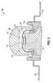
- Fig. 2 illustrates an example of a packaged wavelength-converted green LED suitable for use in LCD 10 of Fig. 1.
- LED die 116 which may be, for example, a 111-nitride light emitting device, is mounted on a submount 118. The submount is supported by a pedestal 110 and is electrically connected to leads 112 by wires 122.
- a lens 120 covers LED die 116.
- the space 114 between LED die 116 and lens 120 is filled with a wavelength-converting material 115.
- the wavelength-converting material may be mixed with another material, such as silicone or epoxy, which has an index of refraction selected to maximize extraction of light from lens 120.
- Fig. 3 illustrates an alternative embodiment of a wavelength converted green LED.
- 111-nitride n-type region 40, active region 38, and p-type region 36 are fabricated on a substrate such as SiC or sapphire.
- Contacts 34 are connected to n-type region 40 and p-type region 36.
- the device is mounted on a submount 30 with interconnects 32 which may be, for example, solder.
- interconnects 32 which may be, for example, solder.
- a reasonable conformal wavelength-converting layer 44 is formed over the top and side surfaces of the LED.
- Wavelength-converting layer 44 may be formed by, for example, stenciling or electrophoretic deposition. Stenciling is described in "Stenciling Phosphor Coatings On Flip Chip Phosphor-LED Devices," U. S. Application Serial No.
- the device shown in Fig. 3 may be packaged in a package similar to that shown in Fig. 2.
- the wavelength-converting material is located in an area of the package that is distant from the LED die, for example, as a coating on the inside or outside of lens 120, or within the material that forms lens 120, in order to reduce the amount of heat to which the wavelength-converting material is exposed.
- Wavelength-converting material 115, 44 is selected to absorb the light emitted by the active region of the LED die and emit green light at a wavelength suitable for use in an LCD.
- the LED die may emit, for example, blue light having a wavelength between about 420 nm and about 460 nm.
- the LED die may emit UV light, for example having a wavelength between about 380 nm and about 420 nm.
- a UV filter may be positioned between the wavelength-converting material and the viewer to prevent UV light from exiting the system towards the viewer.
- Wavelength-converting material 115, 44 may be, for example, a strontium thiogallate phosphor, such as SrGa 2 S 4 :Eu 2+ having a dominant wavelength of about 542 nm, a nitridosilicate phosphor, or any other suitable green-emitting phosphor.
- a strontium thiogallate phosphor such as SrGa 2 S 4 :Eu 2+ having a dominant wavelength of about 542 nm
- a nitridosilicate phosphor or any other suitable green-emitting phosphor.
- an LED die coated with a green-emitting phosphor as the green source in an LCD offers several advantages over the use of an LED die that directly emits green light. It is difficult to fabricate devices which emit exactly the same green color. Generally, green LEDs can range in color from bluish green to yellowish green. Variations in color between different green LEDs in a backlight for an LCD can lead to less saturated colors than would be possible if all LEDs emitted the same green color. Thus, each green LED used as a backlight must emit the same color. Selection of LEDs which emit the same color green light is expensive, as only a few of the green LEDs are useable. In addition, the color emitted by green LEDs can change with temperature and/or driving current. Temperature changes may cause variation in the viewing experience of the display because the color of the direct light changes with temperature and/or because the transmission of the color filters does not change with temperature in the same manner as the LED.
- the LEDs coated with green-emitting phosphors may eliminate the problems encountered with green LEDs.
- the green-emitting phosphor may be selected such that a relatively broad range of pump wavelengths will result in emission of green light, eliminating the need for each LED to emit the same color light, while preserving color uniformity in the display.
- the green-emitting phosphor may be selected for high temperature stability, such as SrGa 2 S 4 :Eu 2+ , eliminating temperature-induced variations in color.
- the thickness of the wavelength-converting material surrounding or coating an LED is selected such that a portion of light emitted by the active region of the LED exits the wavelength-converting layer unconverted
- the wavelength-converting layer must be thick, which can result in increased back-scattering of light in the wavelength-converting layer. Back-scattering increases the likelihood that light will be lost through absorption by semiconductor layers in the LED chip or other portions of the device, which can reduce the total lumen output of the device. Leakage of unconverted light from the active region of the LED mixes with the light emitted by the wavelength-converting material and changes the apparent color of light emitted by the device. In the LCD illustrated in Fig.
- RGB pixel filter 18 most leakage of unconverted light is filtered out by RGB pixel filter 18.
- the effect of leakage of unconverted light can also be minimized by selecting an LED that emits light that is either the same color as the blue LEDs used to make blue light in the backlight (for example, between about 440 nm and about 460 nm), or is such a short wavelength that it is barely visible to the human eye (for example, between about 420 nm and about 440 nm).
- Green phosphor-converted LEDs with the pump wavelength matched to the blue LEDs in the backlight or barely visible to the human eye may also be used in LCDs that do not require RGB pixel filters. Examples of such LCDs are described in "Backlight For A Color LCD," U. S. Application Serial No. 09/854,014, which is incorporated herein by reference.
Landscapes
- Physics & Mathematics (AREA)
- Chemical & Material Sciences (AREA)
- Nonlinear Science (AREA)
- Optics & Photonics (AREA)
- Crystallography & Structural Chemistry (AREA)
- General Physics & Mathematics (AREA)
- Mathematical Physics (AREA)
- Inorganic Chemistry (AREA)
- Engineering & Computer Science (AREA)
- Materials Engineering (AREA)
- Organic Chemistry (AREA)
- Liquid Crystal (AREA)
- Led Device Packages (AREA)
- Planar Illumination Modules (AREA)
- Led Devices (AREA)
Applications Claiming Priority (2)
| Application Number | Priority Date | Filing Date | Title |
|---|---|---|---|
| US10/256,706 US20040061810A1 (en) | 2002-09-27 | 2002-09-27 | Backlight for a color LCD using wavelength-converted light emitting devices |
| US256706 | 2002-09-27 |
Publications (2)
| Publication Number | Publication Date |
|---|---|
| EP1403689A2 true EP1403689A2 (fr) | 2004-03-31 |
| EP1403689A3 EP1403689A3 (fr) | 2005-01-26 |
Family
ID=31977872
Family Applications (1)
| Application Number | Title | Priority Date | Filing Date |
|---|---|---|---|
| EP03103418A Withdrawn EP1403689A3 (fr) | 2002-09-27 | 2003-09-17 | Rétroéclairage pour affichage à cristaux liquides en couleur avec conversion de la longueur d'onde émise par une source lumineuse |
Country Status (4)
| Country | Link |
|---|---|
| US (1) | US20040061810A1 (fr) |
| EP (1) | EP1403689A3 (fr) |
| JP (1) | JP2004118205A (fr) |
| TW (1) | TW200411290A (fr) |
Cited By (5)
| Publication number | Priority date | Publication date | Assignee | Title |
|---|---|---|---|---|
| GB2410612A (en) * | 2004-01-21 | 2005-08-03 | Agilent Technologies Inc | White light and colour controlled LEDs |
| GB2425393A (en) * | 2005-04-18 | 2006-10-25 | Agilent Technologies Inc | Display panel including wavelength converting material |
| GB2442505A (en) * | 2006-10-04 | 2008-04-09 | Sharp Kk | A display with a primary light source for illuminating a nanophosphor re-emission material |
| WO2009000257A3 (fr) * | 2007-06-26 | 2009-02-19 | Osram Opto Semiconductors Gmbh | Puce semi-conductrice optoélectronique |
| DE102008015941A1 (de) * | 2007-12-21 | 2009-06-25 | Osram Opto Semiconductors Gmbh | Beleuchtungseinrichtung |
Families Citing this family (30)
| Publication number | Priority date | Publication date | Assignee | Title |
|---|---|---|---|---|
| US6974229B2 (en) * | 2003-05-21 | 2005-12-13 | Lumileds Lighting U.S., Llc | Devices for creating brightness profiles |
| KR101001040B1 (ko) * | 2003-06-30 | 2010-12-14 | 엘지디스플레이 주식회사 | 액정표시모듈과 그의 구동장치 |
| JP4701642B2 (ja) | 2004-07-05 | 2011-06-15 | 日本電気株式会社 | 表示装置 |
| US7390437B2 (en) * | 2004-08-04 | 2008-06-24 | Intematix Corporation | Aluminate-based blue phosphors |
| US7128432B1 (en) | 2004-09-07 | 2006-10-31 | Sauer-Danfoss Inc. | Backlighted display assembly for an LCD |
| US7724321B2 (en) * | 2004-09-24 | 2010-05-25 | Epistar Corporation | Liquid crystal display |
| KR101116629B1 (ko) | 2004-10-12 | 2012-03-07 | 엘지디스플레이 주식회사 | 백라이트 유닛 및 이를 이용한 액정표시장치 |
| JP4411186B2 (ja) | 2004-11-08 | 2010-02-10 | Nec液晶テクノロジー株式会社 | 液晶表示装置 |
| US7419839B2 (en) * | 2004-11-12 | 2008-09-02 | Philips Lumileds Lighting Company, Llc | Bonding an optical element to a light emitting device |
| US7541728B2 (en) * | 2005-01-14 | 2009-06-02 | Intematix Corporation | Display device with aluminate-based green phosphors |
| TW200636357A (en) * | 2005-04-11 | 2006-10-16 | Chi Lin Technoloogy Co Ltd | Apparatus for mixing light beams and backlight module having the same |
| JP5057692B2 (ja) * | 2005-04-27 | 2012-10-24 | サムソン エルイーディー カンパニーリミテッド. | 発光ダイオードを利用したバックライトユニット |
| US20060285037A1 (en) * | 2005-06-21 | 2006-12-21 | Chi Lin Technology Co., Ltd. | Apparatus for mixing light beams and backlight module having the same |
| JP4816437B2 (ja) * | 2006-01-04 | 2011-11-16 | 日本電気株式会社 | 光源装置およびそれを用いた液晶表示装置 |
| JP2007288139A (ja) * | 2006-03-24 | 2007-11-01 | Sumitomo Chemical Co Ltd | モノシリック発光デバイス及びその駆動方法 |
| US7488087B2 (en) * | 2006-05-19 | 2009-02-10 | Honeywell International Inc. | Light guide and display including a light guide |
| KR20140146210A (ko) * | 2006-06-02 | 2014-12-24 | 히타치가세이가부시끼가이샤 | 광반도체소자 탑재용 패키지 및 이것을 이용한 광반도체장치 |
| TW200842455A (en) * | 2007-04-16 | 2008-11-01 | Chi Lin Technology Co Ltd | Light mixing and guiding device |
| US7859175B2 (en) * | 2007-05-18 | 2010-12-28 | Seiko Instruments Inc. | Illuminating device, display device and optical film |
| US20100181590A1 (en) * | 2007-06-25 | 2010-07-22 | Jen-Shyan Chen | Light-emitting diode illuminating apparatus |
| US8585273B2 (en) * | 2007-07-31 | 2013-11-19 | Rambus Delaware Llc | Illumination assembly including wavelength converting material |
| US20090034230A1 (en) | 2007-07-31 | 2009-02-05 | Luminus Devices, Inc. | Illumination assembly including wavelength converting material having spatially varying density |
| KR100990640B1 (ko) * | 2008-05-29 | 2010-10-29 | 삼성엘이디 주식회사 | 확산렌즈 및 확산렌즈를 이용한 발광소자 조립체 |
| GB2463266B (en) * | 2008-09-05 | 2011-07-27 | Plastic Logic Ltd | Electronic document reader |
| JP5395097B2 (ja) * | 2009-01-13 | 2014-01-22 | 株式会社小糸製作所 | 発光モジュールおよび灯具ユニット |
| JP2011211047A (ja) * | 2010-03-30 | 2011-10-20 | Sharp Corp | 表示装置、表示装置の製造方法および表示装置の駆動方法 |
| US20170139105A1 (en) * | 2015-11-17 | 2017-05-18 | Glo Ab | Integrated back light unit with remote phosphor |
| US10600354B2 (en) | 2016-04-22 | 2020-03-24 | Glo Ab | Small pitch direct view display and method of making thereof |
| TW202119652A (zh) * | 2019-10-31 | 2021-05-16 | 隆達電子股份有限公司 | 顯示裝置及其製造方法 |
| US12463077B2 (en) | 2019-10-31 | 2025-11-04 | Lextar Electronics Corporation | Method of manufacturing display device |
Family Cites Families (21)
| Publication number | Priority date | Publication date | Assignee | Title |
|---|---|---|---|---|
| US5315418A (en) * | 1992-06-17 | 1994-05-24 | Xerox Corporation | Two path liquid crystal light valve color display with light coupling lens array disposed along the red-green light path |
| US5396406A (en) * | 1993-02-01 | 1995-03-07 | Display Technology Industries | Thin high efficiency illumination system for display devices |
| US20020001050A1 (en) * | 1993-06-30 | 2002-01-03 | Pope Edward J.A. | Fluorescent liquid crystal displays and methods of making same |
| US6218774B1 (en) * | 1993-06-30 | 2001-04-17 | Edward J. A. Pope | Photoluminescent/electroluminescent display screen |
| US5613751A (en) * | 1995-06-27 | 1997-03-25 | Lumitex, Inc. | Light emitting panel assemblies |
| JP3419280B2 (ja) * | 1996-11-05 | 2003-06-23 | 日亜化学工業株式会社 | 発光装置 |
| JP3466433B2 (ja) * | 1996-11-12 | 2003-11-10 | シャープ株式会社 | 液晶表示装置 |
| DE59814117D1 (de) * | 1997-03-03 | 2007-12-20 | Philips Intellectual Property | Weisse lumineszenzdiode |
| JP3585097B2 (ja) * | 1998-06-04 | 2004-11-04 | セイコーエプソン株式会社 | 光源装置,光学装置および液晶表示装置 |
| JP2000031548A (ja) * | 1998-07-09 | 2000-01-28 | Stanley Electric Co Ltd | 面実装型発光ダイオードおよびその製造方法 |
| KR100450542B1 (ko) * | 1998-10-29 | 2004-10-01 | 가부시키가이샤 히타치세이사쿠쇼 | 조명 장치 및 이를 이용한 액정 표시 장치 |
| US6212213B1 (en) * | 1999-01-29 | 2001-04-03 | Agilent Technologies, Inc. | Projector light source utilizing a solid state green light source |
| US6273589B1 (en) * | 1999-01-29 | 2001-08-14 | Agilent Technologies, Inc. | Solid state illumination source utilizing dichroic reflectors |
| EP1142033A1 (fr) * | 1999-09-27 | 2001-10-10 | LumiLeds Lighting U.S., LLC | Dispositif a diode emetteur de lumiere produisant une lumiere blanche par totale conversion au phosphore |
| EP1104799A1 (fr) * | 1999-11-30 | 2001-06-06 | Patent-Treuhand-Gesellschaft für elektrische Glühlampen mbH | Materiau luminescent émetteur de lumière rouge |
| JP3301752B2 (ja) * | 2000-03-31 | 2002-07-15 | 三菱電機株式会社 | フロントライト、反射型液晶表示装置および携帯情報端末 |
| JP2002217454A (ja) * | 2001-01-19 | 2002-08-02 | Matsushita Electric Ind Co Ltd | Ledアレー及びこれを用いたled表示装置 |
| JP2002245825A (ja) * | 2001-02-15 | 2002-08-30 | Nec Corp | バックライト、液晶表示装置及び電子機器 |
| JP3940596B2 (ja) * | 2001-05-24 | 2007-07-04 | 松下電器産業株式会社 | 照明光源 |
| DE10146719A1 (de) * | 2001-09-20 | 2003-04-17 | Patent Treuhand Ges Fuer Elektrische Gluehlampen Mbh | Beleuchtungseinheit mit mindestens einer LED als Lichtquelle |
| US6809471B2 (en) * | 2002-06-28 | 2004-10-26 | General Electric Company | Phosphors containing oxides of alkaline-earth and Group-IIIB metals and light sources incorporating the same |
-
2002
- 2002-09-27 US US10/256,706 patent/US20040061810A1/en not_active Abandoned
-
2003
- 2003-09-17 EP EP03103418A patent/EP1403689A3/fr not_active Withdrawn
- 2003-09-24 TW TW092126347A patent/TW200411290A/zh unknown
- 2003-09-29 JP JP2003337370A patent/JP2004118205A/ja active Pending
Cited By (11)
| Publication number | Priority date | Publication date | Assignee | Title |
|---|---|---|---|---|
| GB2410612A (en) * | 2004-01-21 | 2005-08-03 | Agilent Technologies Inc | White light and colour controlled LEDs |
| GB2425393A (en) * | 2005-04-18 | 2006-10-25 | Agilent Technologies Inc | Display panel including wavelength converting material |
| US7535524B2 (en) | 2005-04-18 | 2009-05-19 | Avago Technologies Ecbu Ip (Singapore) Pte. Ltd. | Display panel with wavelength converting material and control interface to switchably control independent projection or non-projection of primary and secondary IMAGES |
| GB2425393B (en) * | 2005-04-18 | 2011-06-29 | Agilent Technologies Inc | Display panel |
| GB2442505A (en) * | 2006-10-04 | 2008-04-09 | Sharp Kk | A display with a primary light source for illuminating a nanophosphor re-emission material |
| EP1909134A3 (fr) * | 2006-10-04 | 2008-12-17 | Sharp Kabushiki Kaisha | Affichage |
| US7686493B2 (en) | 2006-10-04 | 2010-03-30 | Sharp Kabushiki Kaisha | Display |
| WO2009000257A3 (fr) * | 2007-06-26 | 2009-02-19 | Osram Opto Semiconductors Gmbh | Puce semi-conductrice optoélectronique |
| US8299484B2 (en) | 2007-06-26 | 2012-10-30 | Osram Opto Semiconductors Gmbh | Optoelectronic semiconductor chip |
| DE102008015941A1 (de) * | 2007-12-21 | 2009-06-25 | Osram Opto Semiconductors Gmbh | Beleuchtungseinrichtung |
| US8716729B2 (en) | 2007-12-21 | 2014-05-06 | Osram Opto Semiconductors Gmbh | Lighting device |
Also Published As
| Publication number | Publication date |
|---|---|
| US20040061810A1 (en) | 2004-04-01 |
| JP2004118205A (ja) | 2004-04-15 |
| EP1403689A3 (fr) | 2005-01-26 |
| TW200411290A (en) | 2004-07-01 |
Similar Documents
| Publication | Publication Date | Title |
|---|---|---|
| EP1403689A2 (fr) | Rétroéclairage pour affichage à cristaux liquides en couleur avec conversion de la longueur d'onde émise par une source lumineuse | |
| US7248310B2 (en) | Flat panel energized by blue LED for generating white light | |
| CN1983590B (zh) | 高亮度发光二极管和使用其的液晶显示装置 | |
| JP5938213B2 (ja) | 波長変換半導体発光装置及びフィルタを含む光源 | |
| JP6496023B2 (ja) | 表示装置及びテレビ受信装置 | |
| JP2010092705A (ja) | 照明装置及びこれを用いた表示装置 | |
| US10763401B2 (en) | Backlight unit and display apparatus including the same | |
| US8226257B2 (en) | Backlight unit and display including the same | |
| WO2011105146A1 (fr) | Dispositif d'affichage et dispositif de réception de télévision | |
| CN108073005A (zh) | 显示设备 | |
| JP2008227423A (ja) | 光源装置及び液晶表示装置 | |
| KR20120056001A (ko) | 백라이트 유닛 및 액정표시장치 | |
| KR20150080135A (ko) | 액정표시장치 | |
| US20170068127A1 (en) | Optical filter and photoluminescence display employing the same | |
| JP7683340B2 (ja) | ブラックマトリクス基板、及びブラックマトリクス基板を備えた表示装置 | |
| KR101946263B1 (ko) | 액정표시장치 | |
| KR20130058264A (ko) | 액정표시장치 | |
| KR20160080486A (ko) | 발광다이오드 패키지 및 이를 포함하는 백라이트 유닛 | |
| KR20100132149A (ko) | 편광 광원 및 형광체 필터를 채택한 액정 디스플레이 | |
| KR101684611B1 (ko) | 액정표시장치 | |
| KR102449134B1 (ko) | 투명 액정표시장치 | |
| JP5444919B2 (ja) | 照明装置、及び液晶表示装置 | |
| KR101757751B1 (ko) | 엘이디 어셈블리 및 이를 포함하는 액정표시장치 | |
| KR101717652B1 (ko) | 컬러필터층 및 이를 구비한 액정표시소자 | |
| KR101943958B1 (ko) | 발광 다이오드 패키지 및 이를 구비한 백라이트 유닛 |
Legal Events
| Date | Code | Title | Description |
|---|---|---|---|
| PUAI | Public reference made under article 153(3) epc to a published international application that has entered the european phase |
Free format text: ORIGINAL CODE: 0009012 |
|
| AK | Designated contracting states |
Kind code of ref document: A2 Designated state(s): AT BE BG CH CY CZ DE DK EE ES FI FR GB GR HU IE IT LI LU MC NL PT RO SE SI SK TR |
|
| AX | Request for extension of the european patent |
Extension state: AL LT LV MK |
|
| PUAL | Search report despatched |
Free format text: ORIGINAL CODE: 0009013 |
|
| AK | Designated contracting states |
Kind code of ref document: A3 Designated state(s): AT BE BG CH CY CZ DE DK EE ES FI FR GB GR HU IE IT LI LU MC NL PT RO SE SI SK TR |
|
| AX | Request for extension of the european patent |
Extension state: AL LT LV MK |
|
| RIC1 | Information provided on ipc code assigned before grant |
Ipc: 7H 01L 33/00 B Ipc: 7C 09K 11/08 B Ipc: 7G 02F 1/13357A |
|
| 17P | Request for examination filed |
Effective date: 20050726 |
|
| AKX | Designation fees paid |
Designated state(s): DE |
|
| STAA | Information on the status of an ep patent application or granted ep patent |
Free format text: STATUS: THE APPLICATION IS DEEMED TO BE WITHDRAWN |
|
| 18D | Application deemed to be withdrawn |
Effective date: 20060607 |
|
| R18D | Application deemed to be withdrawn (corrected) |
Effective date: 20060808 |