EP1403864A2 - Appareil électronique et procédé anti-choc - Google Patents
Appareil électronique et procédé anti-choc Download PDFInfo
- Publication number
- EP1403864A2 EP1403864A2 EP03021017A EP03021017A EP1403864A2 EP 1403864 A2 EP1403864 A2 EP 1403864A2 EP 03021017 A EP03021017 A EP 03021017A EP 03021017 A EP03021017 A EP 03021017A EP 1403864 A2 EP1403864 A2 EP 1403864A2
- Authority
- EP
- European Patent Office
- Prior art keywords
- signal
- disk device
- sensor
- electronic apparatus
- head
- Prior art date
- Legal status (The legal status is an assumption and is not a legal conclusion. Google has not performed a legal analysis and makes no representation as to the accuracy of the status listed.)
- Withdrawn
Links
Images


Classifications
-
- G—PHYSICS
- G11—INFORMATION STORAGE
- G11B—INFORMATION STORAGE BASED ON RELATIVE MOVEMENT BETWEEN RECORD CARRIER AND TRANSDUCER
- G11B19/00—Driving, starting, stopping record carriers not specifically of filamentary or web form, or of supports therefor; Control thereof; Control of operating function ; Driving both disc and head
- G11B19/02—Control of operating function, e.g. switching from recording to reproducing
- G11B19/04—Arrangements for preventing, inhibiting, or warning against double recording on the same blank or against other recording or reproducing malfunctions
-
- G—PHYSICS
- G11—INFORMATION STORAGE
- G11B—INFORMATION STORAGE BASED ON RELATIVE MOVEMENT BETWEEN RECORD CARRIER AND TRANSDUCER
- G11B5/00—Recording by magnetisation or demagnetisation of a record carrier; Reproducing by magnetic means; Record carriers therefor
- G11B5/48—Disposition or mounting of heads or head supports relative to record carriers ; arrangements of heads, e.g. for scanning the record carrier to increase the relative speed
- G11B5/54—Disposition or mounting of heads or head supports relative to record carriers ; arrangements of heads, e.g. for scanning the record carrier to increase the relative speed with provision for moving the head into or out of its operative position or across tracks
Definitions
- the present invention relates to a shockproof technique that takes a measure against any shock acting when an electronic apparatus which incorporates, e.g., a magnetic disk device is dropped.
- PDAs personal digital assistants
- Jpn. Pat. Appln. KOKAI Publication Nos. 2000-14783, 2000-67770, and the like describe a shockproof method in a magnetic disk device.
- a magnetic disk device itself incorporates a fall sensor and a mechanism for retracting the magnetic head on the basis of the detection result of the fall sensor.
- each individual magnetic disk device must have a fall sensor and its control mechanism.
- the fall sensor and control mechanism become superfluous. That is, this mechanism is unnecessary unless it is operated while built into a portable device which is likely to fall, and merely increases cost.
- two different types of magnetic disk devices with and without such a mechanism must be manufactured.
- Jpn. Pat. Appln. KOKAI Publication Nos. 2000-339893 and 6-203505 since a fall sensor, a control unit for retracting a magnetic head, and the like are provided on the electronic apparatus side, the above-mentioned inefficiency is avoided.
- Jpn. Pat. Appln. KOKAI Publication Nos. 2000-339893 and 6-203505 upon detecting the fall of the apparatus itself, a magnetic head retraction (unload) command is issued to a magnetic disk device.
- the magnetic disk device cannot accept any command during data write, read, or seek access. That is, even when an unload command is added, and is immediately issued upon detection of a fall, if another command process is in progress, the magnetic head is unloaded after that process, and the apparatus may crash against the ground before the magnetic head is completely unloaded.
- the present invention has been made in consideration of the above situation, and has as its object to provide an electronic apparatus which can quickly and reliably move a magnetic head of a magnetic disk device to an unload area, and a shockproof method for an electronic apparatus.
- the present invention provides an electronic apparatus characterized by comprising a disk device having a head, a sensor which detects a fall, and control means for controlling the disk device to move the head to an unload area using a signal which is independent from commands that are processed by the disk device in an order in which they are accepted, when the sensor detects the fall.
- the present invention provides an electronic apparatus which can quickly and reliably move a magnetic head of a magnetic disk device to an unload area, and a shockproof method for an electronic apparatus.
- FIG. 1 is a view for explaining the use environment of an electronic apparatus according to an embodiment of the present invention.
- an electronic apparatus 1 of this embodiment is a storage device which incorporates a battery and has a wireless communication function.
- the storage device effects wireless communication with such information apparatuses as a personal computer 2, portable game machine 3, digital video camera 4, and PDA 5.
- This electronic apparatus 1 and information apparatuses 2 to 5 comprise Bluetooth modules, and effect wireless data communication via those Bluetooth modules.
- the maximum wireless communication range of the Bluetooth modules is about 100 m.
- a Bluetooth link is automatically established to allow data exchange.
- the electronic apparatus 1 also has a USB connector that receives a USB cable, and comprises a wired communication function that effects wired data communication via this USB connector.
- FIG. 2 is a block diagram showing the arrangement of this electronic apparatus 1.
- this electronic apparatus 1 has an engine unit 11, Bluetooth wireless unit 12, power supply unit 13, setup operation unit 14, and data storage unit 15.
- the engine unit 11 controls the overall electronic apparatus 1.
- a CPU 21 as a core of this engine unit 11 is connected to an EEPROM 22 via a bus 26.
- the EEPROM 22 stores various kinds of control information including threshold value data A (to be described later).
- the CPU 21 is connected to a CPU bus/PCI bus bridge 25 via a CPU bus 27.
- a flash memory 23 is connected to the CPU bus/PCI bus bridge 25 via a memory bus 28, and a DRAM 24 is also connected to it via a memory bus 29.
- the flash memory 23 stores various programs which include shockproof control program B (to be described later) that describe the operation sequence of the CPU 21.
- the DRAM 24 is used as a work memory of the CPU 21.
- the DRAM 24 is used as a buffer area of the data storage unit 15.
- the CPU bus/PCI bus bridge 25 is an interface bridge between the CPU bus 27 and a PCI bus 41, and is connected to a display controller 31 via a bus 30.
- the display controller 31 executes display control of an LCD 33 which is connected to it via a bus 32.
- the PCI bus 41 is connected to an ISA bus 43 via a PCI/ISA bridge 42.
- the PCI bus 41 is connected to the Bluetooth wireless unit 12 and a USB interface 44 via a USB host controller 46.
- a USB connector 45 used to connect an information apparatus via a cable is connected to the USB interface 44.
- the Bluetooth wireless unit 12 comprises a baseband LSI 51, flash memory 52, antenna 54, and RF unit 53.
- the baseband LSI 51 is connected to the USB host controller 46, and controls a Bluetooth wireless function.
- the flash memory 52 stores a program to be executed by the baseband LSI 51.
- the RF unit 53 controls an RF signal between the baseband LSI 51 and antenna 54.
- the data storage unit 15 is connected to the PCI bus 41.
- the data storage unit 15 has an IDE interface controller 61 and a magnetic disk drive device (to be referred to as an HDD hereinafter) 63.
- the IDE interface controller 61 is connected via the PCI bus 41.
- the HDD 63 is connected to the IDE interface controller 61 via an IDE interface 62.
- the HDD 63 rotates a magnetic disk 631 at high speed, and brings a read/write magnetic head 633 provided on the distal end of an arm 632 closer to the surface of the magnetic disk 631, thus reading/writing data. Therefore, when the HDD experiences a shock during its operation, these components are damaged.
- the HDD 63 has a mechanism for retracting the magnetic head 633 to a predetermined position (ramp mechanism 634) as a so-called shockproof mechanism.
- FIG. 4 shows the state wherein the magnetic head 633 is retracted to the ramp mechanism 634.
- This electronic apparatus 1 is characterized by quickly and reliably activating this shockproof mechanism, and such characteristic feature will be explained later.
- the power supply unit 13 is connected to the PCI bus 41.
- the power supply unit 13 comprises a power supply controller 71 and a power supply control circuit 73.
- the power supply controller 71 is connected to the PCI bus 41.
- the power supply control circuit 73 is connected to the power supply controller 71.
- a battery 74 and AC input 75 are connected to the power supply control circuit 73.
- the battery 74 supplies electric power.
- the AC input 75 supplies electric power. Electric power from the battery 74 or AC input 75 is supplied to components required to operate the electronic apparatus 1, e.g., the engine unit 11, wireless unit 12, data storage unit 15, and the like.
- the setup operation unit 14 is connected to the ISA bus 43.
- the setup operation unit 14 includes an I/O controller 81, and a button 82 and rotary switch 83.
- the I/O controller 81 is connected to the ISA bus 43.
- the button 82 and rotary switch 83 are connected to the I/O controller 81.
- the button 82 and rotary switch 83 are used to set up the operation environment of the electronic apparatus 1 and to start up the apparatus. Threshold value data A described above is set up using this setup operation unit 14.
- a real-time clock (RTC) 91 is connected to the ISA bus 43.
- the RTC 91 is a timing module which operates on its own built-in battery, and measures the system time using a plurality of registers.
- an agravity sensor 92 and low-pass filter 93 are provided to this electronic apparatus 1.
- the agravity sensor 92 is a mechanical switch, which is opened in an agravity state, and has a structure shown in, e.g., FIG. 5.
- the agravity sensor 92 In a normal state, the agravity sensor 92 is set so that an inner iron ball 921 contacts the inner wall of a surrounding case 922 as a conductor. As a result, signal lines X and Y are electrically connected.
- the iron ball 921 separates from the inner wall of the surrounding case 922 and, as a result, signal lines X and Y are disconnected.
- This agravity sensor 92 is opened every time a shock that is light enough to continue the system operation acts. As a result, the sensor 92 is repeatedly opened/closed within a short period, and generates a so-called chattering signal.
- the low-pass filter 93 is provided to absorb the chattering signal generated by the agravity sensor 92.
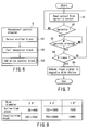
- FIG. 6 shows functional blocks of this shockproof control program B.
- shockproof control program B has respective processing blocks, i.e., a sensor monitor block 101, fall detection block 102, and HDD drive control block 103.
- the sensor monitor block 101 monitors if an open signal that has passed through the low-pass filter 93 is output from the agravity sensor 92. Upon detection of the output open signal, the sensor monitor block 101 informs the fall detection block 102 accordingly.
- the fall detection block 102 detects if the associated apparatus is falling. Upon reception of information from the sensor monitor block 101, the block 102 checks if that information continues. If the information continues, the fall detection block 102 checks M seconds later if that information continues. When this information is repeatedly detected N times, the fall detection block 102 determines that the associated apparatus is falling.
- M and N are given by threshold value data A in the EEPROM 22. For example, an agravity state in daily life (e.g., during walking) continues 100 ms or less at longest. Hence, if an agravity state continues 100 ms or longer, since falling can be determined, a combination of M and N is set to have, e.g., 100 ms as a threshold value. By setting M and N using threshold value data A in the EEPROM 22, various use environments can be flexibly coped with. When it is determined that the associated apparatus is falling, the fall detection block 102 informs the HDD drive control block 103 accordingly.
- the HDD drive control block 103 effects control to retract the magnetic head 632 of the HDD 63 to the ramp mechanism 633 against a shock upon crash.
- the block 103 Upon receiving information from the fall detection block 102, the block 103 instructs the IDE interface controller 61 to transmit an unload signal to the HDD 63.
- the HDD drive control block 103 uses a reset signal independent from general commands such as a read signal, write signal, and the like, which are processed in the order they are accepted. With this signal, the unload process can be quickly and reliably executed irrespective of the operation state of the HDD 63.
- FIG. 7 is a flowchart showing the operation sequence of shockproof control of the HDD 63 executed by shockproof control program B.
- Shockproof control program B reads out the output from the agravity sensor 92 via the low-pass filter 93 (step S1). If this output indicates a closed state, i.e., it does not sense any agravity (NO in step S2), shockproof control program B determines that the associated apparatus is not falling (step S3).
- shockproof control program B waits for M seconds given by threshold value data A (step S4), and then repeats processes from step S1. If this repetition continues N times given by threshold value data A (YES in step S5), shockproof control program B determines that the associated apparatus is falling, and outputs an unload signal to the HDD 63 (step S6).
- the electronic apparatus 1 of this embodiment controls the HDD 63 to unload using the reset signal, the magnetic head 632 of the HDD 63 can be quickly and reliably retracted to the ramp mechanism 633.
- an HDD can withstand shocks to degrees shown in FIG. 8.
- a 1.8" HDD can withstand an active-time(operating) shock up to 200G, and an inactive-time(non-operating) shock up to 1000G.
- it is required as shockproof specifications to provide a shock-absorbing mechanism for absorbing an active-time(operating) shock to be 200G or less, and an inactive-time(non-operating) shock to be 1000G or less.
- absorption of the former active-time(operating) shock is in question here.
- a shock-absorbing mechanism which has excessive shock-absorption power results in increases in cost and size.
- FIG. 9 is a block diagram showing the arrangement of an electronic apparatus 1 of the second embodiment.
- a signal line 64 that exchanges with the HDD 63 an unload signal as a signal independent from general commands such as a read signal, write signal, and the like, which are processed in the order they are accepted, is added.
- the HDD drive control block 103 Upon receiving information from the fall detection block 102, the HDD drive control block 103 transmits a signal which is defined in advance as an unload signal with the HDD 63 via the signal line 64 to the HDD 63 in place of instructing the IDE interface controller 61 to transmit a reset signal to the HDD 63.
- the magnetic head 632 of the HDD 63 can be quickly and reliably retracted to the ramp mechanism 633, and a shock-absorbing mechanism having appropriate shock absorbing power can be arranged, although a signal that deviates from the interface standard must be used.
Landscapes
- Signal Processing For Digital Recording And Reproducing (AREA)
- Moving Of Head For Track Selection And Changing (AREA)
- Adjustment Of The Magnetic Head Position Track Following On Tapes (AREA)
- Supporting Of Heads In Record-Carrier Devices (AREA)
- Power Sources (AREA)
Applications Claiming Priority (2)
| Application Number | Priority Date | Filing Date | Title |
|---|---|---|---|
| JP2002287118A JP2004127364A (ja) | 2002-09-30 | 2002-09-30 | 電子機器および衝撃対策方法 |
| JP2002287118 | 2002-09-30 |
Publications (2)
| Publication Number | Publication Date |
|---|---|
| EP1403864A2 true EP1403864A2 (fr) | 2004-03-31 |
| EP1403864A3 EP1403864A3 (fr) | 2004-07-07 |
Family
ID=31973435
Family Applications (1)
| Application Number | Title | Priority Date | Filing Date |
|---|---|---|---|
| EP03021017A Withdrawn EP1403864A3 (fr) | 2002-09-30 | 2003-09-17 | Appareil électronique et procédé anti-choc |
Country Status (4)
| Country | Link |
|---|---|
| US (1) | US20040125490A1 (fr) |
| EP (1) | EP1403864A3 (fr) |
| JP (1) | JP2004127364A (fr) |
| CN (1) | CN1240053C (fr) |
Families Citing this family (13)
| Publication number | Priority date | Publication date | Assignee | Title |
|---|---|---|---|---|
| JP2005346741A (ja) * | 2004-05-31 | 2005-12-15 | Toshiba Corp | ディスク記憶装置及び同装置に適用される緊急ヘッド退避制御回路 |
| US7190540B2 (en) * | 2004-06-03 | 2007-03-13 | Sony Corporation | Portable apparatus having head retracting function and head retracting method |
| EP1630726B1 (fr) * | 2004-08-18 | 2009-09-23 | Sony Corporation | Carte à mémoire, procédé de commande de carte mémoire, procédé de commande d'accès pour carte mémoire et programmes informatiques associés |
| JP4519626B2 (ja) | 2004-12-17 | 2010-08-04 | 株式会社東芝 | 電子機器およびディスク保護方法 |
| CN1897140B (zh) * | 2005-07-13 | 2012-07-18 | 日本胜利株式会社 | 记录再生装置 |
| US8762601B2 (en) * | 2005-11-14 | 2014-06-24 | Lenovo (Singapore) Pte. Ltd. | Apparatus, system, and method for buffering write data in response to motion |
| US7733595B2 (en) | 2006-01-06 | 2010-06-08 | Lucas Andrew A | Hard disk drive with external sensor interface, system for use thereof and method |
| US7430452B2 (en) * | 2006-01-17 | 2008-09-30 | Lenovo (Singapore) Pte. Ltd. | Apparatus, system, and method for selectivity protecting a motion sensitive component in a computerized device |
| JP4868951B2 (ja) * | 2006-06-09 | 2012-02-01 | 東芝ストレージデバイス株式会社 | 制御装置、記憶装置およびヘッド退避方法 |
| KR100734322B1 (ko) | 2006-06-27 | 2007-07-02 | 삼성전자주식회사 | 하드디스크 드라이브의 기록 제어 방법 및 이에 적합한장치 |
| JP2008108291A (ja) * | 2006-10-23 | 2008-05-08 | Hitachi Global Storage Technologies Netherlands Bv | ディスク・ドライブ装置及びそのヘッド退避方法 |
| JP5159819B2 (ja) * | 2010-03-29 | 2013-03-13 | 株式会社東芝 | 電子機器 |
| JP2012033266A (ja) * | 2011-11-16 | 2012-02-16 | Toshiba Corp | 電子機器 |
Family Cites Families (12)
| Publication number | Priority date | Publication date | Assignee | Title |
|---|---|---|---|---|
| DE3929082A1 (de) * | 1988-12-09 | 1990-06-13 | Teves Gmbh Alfred | Beschleunigungssensor mit einseitig eingespanntem biegebalken |
| US5227929A (en) * | 1990-11-26 | 1993-07-13 | International Business Machines Corporation | Portable computer hard disk protective reflex system |
| US5835298A (en) * | 1996-08-16 | 1998-11-10 | Telxon Corporation | Hard drive protection system and method |
| US5982573A (en) * | 1993-12-15 | 1999-11-09 | Hewlett-Packard Company | Disk drive and method for minimizing shock-induced damage |
| US6046877A (en) * | 1995-02-16 | 2000-04-04 | Mobile Storage Technology, Inc. | Protection apparatus and method for hard disk drive unit of a portable computer |
| US5721457A (en) * | 1995-04-28 | 1998-02-24 | International Business Machines Corporation | Shock isolation system with write inhibit |
| CA2330512C (fr) * | 2000-01-12 | 2003-12-30 | Ubukata Industries Co., Ltd. | Detecteur de chute libre |
| JP2001273707A (ja) * | 2000-03-28 | 2001-10-05 | Internatl Business Mach Corp <Ibm> | 回転記憶装置および情報記録方法 |
| JP4491114B2 (ja) * | 2000-06-23 | 2010-06-30 | 株式会社日立グローバルストレージテクノロジーズ | 落下感知センサ及びこれを用いた情報処理装置 |
| US6520013B1 (en) * | 2000-10-02 | 2003-02-18 | Apple Computer, Inc. | Method and apparatus for detecting free fall |
| JP3787491B2 (ja) * | 2000-11-20 | 2006-06-21 | 株式会社日立グローバルストレージテクノロジーズ | 磁気ディスク装置 |
| TW568322U (en) * | 2001-08-16 | 2003-12-21 | Acer Inc | Shock absorber module |
-
2002
- 2002-09-30 JP JP2002287118A patent/JP2004127364A/ja active Pending
-
2003
- 2003-09-17 EP EP03021017A patent/EP1403864A3/fr not_active Withdrawn
- 2003-09-29 CN CN03160166.9A patent/CN1240053C/zh not_active Expired - Fee Related
- 2003-09-30 US US10/673,169 patent/US20040125490A1/en not_active Abandoned
Also Published As
| Publication number | Publication date |
|---|---|
| EP1403864A3 (fr) | 2004-07-07 |
| US20040125490A1 (en) | 2004-07-01 |
| CN1506941A (zh) | 2004-06-23 |
| JP2004127364A (ja) | 2004-04-22 |
| CN1240053C (zh) | 2006-02-01 |
Similar Documents
| Publication | Publication Date | Title |
|---|---|---|
| EP1403864A2 (fr) | Appareil électronique et procédé anti-choc | |
| US7744423B2 (en) | USB connector conversion device | |
| US7882375B2 (en) | Power off controllers and memory storage apparatus including the same and methods for operating the same | |
| JP4471389B2 (ja) | デュアル加速度センサシステム | |
| US8081237B2 (en) | Data recording apparatus and method for protecting hard disk drive and computer program | |
| US5475271A (en) | Power source control system for electronic device and expansion unit connected thereto | |
| US20030175560A1 (en) | Upgradable smart battery pack | |
| US20140306529A1 (en) | Dynamic charging of a rechargeable battery | |
| KR20140039657A (ko) | 호스트 장치, 사용자 단말 장치, 이들을 이용한 충전 방법 및 통신 방법 | |
| US20040225836A1 (en) | Portable USB storage device capable of being set to device mode or host mode | |
| EP1742071A1 (fr) | Dispositif électronique et procédé de détection de chute | |
| JP2003263240A (ja) | 電子機器および衝撃対策方法 | |
| US20030051178A1 (en) | Mechanism for wireless modem power control | |
| JP3824511B2 (ja) | コンピュータ装置および無線通信モジュールの制御方法 | |
| KR101871427B1 (ko) | 데이터 보호 및 복구 기능을 갖는 usb 메모리 장치 | |
| US20120120586A1 (en) | Device, and device mounting apparatus | |
| JP2007101406A (ja) | 落下検出方法及び携帯端末装置 | |
| US20190138486A1 (en) | Hot unplug predictions based on latch positions | |
| JP2004355775A (ja) | ハードディスクユニット及びその落下基準時間の設定又は確認方法 | |
| US20100259847A1 (en) | Portable apparatus having electronic control system and control method thereof | |
| KR101491149B1 (ko) | 무선랜 단말장치 및 접속 방법 | |
| EP4250172B1 (fr) | Dispositif électronique | |
| KR20090007555U (ko) | 충전기 겸용 데이터 저장 장치 | |
| JP2006268925A (ja) | データ保護システム、データ保護装置 | |
| KR101314379B1 (ko) | Usb 허브를 겸비한 usb 메모리 스틱장치 및 그 구동방법 |
Legal Events
| Date | Code | Title | Description |
|---|---|---|---|
| PUAI | Public reference made under article 153(3) epc to a published international application that has entered the european phase |
Free format text: ORIGINAL CODE: 0009012 |
|
| 17P | Request for examination filed |
Effective date: 20030917 |
|
| AK | Designated contracting states |
Kind code of ref document: A2 Designated state(s): AT BE BG CH CY CZ DE DK EE ES FI FR GB GR HU IE IT LI LU MC NL PT RO SE SI SK TR |
|
| AX | Request for extension of the european patent |
Extension state: AL LT LV MK |
|
| PUAL | Search report despatched |
Free format text: ORIGINAL CODE: 0009013 |
|
| AK | Designated contracting states |
Kind code of ref document: A3 Designated state(s): AT BE BG CH CY CZ DE DK EE ES FI FR GB GR HU IE IT LI LU MC NL PT RO SE SI SK TR |
|
| AX | Request for extension of the european patent |
Extension state: AL LT LV MK |
|
| RIC1 | Information provided on ipc code assigned before grant |
Ipc: 7G 11B 5/55 B Ipc: 7G 11B 5/54 B Ipc: 7H 01H 35/14 B Ipc: 7G 11B 19/04 A |
|
| 17Q | First examination report despatched |
Effective date: 20040922 |
|
| AKX | Designation fees paid |
Designated state(s): DE FR GB |
|
| STAA | Information on the status of an ep patent application or granted ep patent |
Free format text: STATUS: THE APPLICATION IS DEEMED TO BE WITHDRAWN |
|
| 18D | Application deemed to be withdrawn |
Effective date: 20060713 |