EP1403890B1 - Positionsschalter - Google Patents
Positionsschalter Download PDFInfo
- Publication number
- EP1403890B1 EP1403890B1 EP03021431A EP03021431A EP1403890B1 EP 1403890 B1 EP1403890 B1 EP 1403890B1 EP 03021431 A EP03021431 A EP 03021431A EP 03021431 A EP03021431 A EP 03021431A EP 1403890 B1 EP1403890 B1 EP 1403890B1
- Authority
- EP
- European Patent Office
- Prior art keywords
- housing
- contact
- position switch
- switch according
- terminals
- Prior art date
- Legal status (The legal status is an assumption and is not a legal conclusion. Google has not performed a legal analysis and makes no representation as to the accuracy of the status listed.)
- Expired - Lifetime
Links
- 238000003780 insertion Methods 0.000 claims abstract description 15
- 230000037431 insertion Effects 0.000 claims abstract description 15
- 239000004020 conductor Substances 0.000 description 5
- 238000011161 development Methods 0.000 description 3
- 230000018109 developmental process Effects 0.000 description 3
- 230000015572 biosynthetic process Effects 0.000 description 2
- 238000005755 formation reaction Methods 0.000 description 2
- 238000005096 rolling process Methods 0.000 description 2
- 230000004308 accommodation Effects 0.000 description 1
- 230000001419 dependent effect Effects 0.000 description 1
- 230000000694 effects Effects 0.000 description 1
- 230000002401 inhibitory effect Effects 0.000 description 1
- 238000004519 manufacturing process Methods 0.000 description 1
- 230000001681 protective effect Effects 0.000 description 1
- 238000010079 rubber tapping Methods 0.000 description 1
Images



Classifications
-
- H—ELECTRICITY
- H01—ELECTRIC ELEMENTS
- H01H—ELECTRIC SWITCHES; RELAYS; SELECTORS; EMERGENCY PROTECTIVE DEVICES
- H01H1/00—Contacts
- H01H1/12—Contacts characterised by the manner in which co-operating contacts engage
- H01H1/14—Contacts characterised by the manner in which co-operating contacts engage by abutting
- H01H1/20—Bridging contacts
-
- H—ELECTRICITY
- H01—ELECTRIC ELEMENTS
- H01H—ELECTRIC SWITCHES; RELAYS; SELECTORS; EMERGENCY PROTECTIVE DEVICES
- H01H13/00—Switches having rectilinearly-movable operating part or parts adapted for pushing or pulling in one direction only, e.g. push-button switch
- H01H13/02—Details
- H01H13/12—Movable parts; Contacts mounted thereon
- H01H13/14—Operating parts, e.g. push-button
- H01H13/18—Operating parts, e.g. push-button adapted for actuation at a limit or other predetermined position in the path of a body, the relative movement of switch and body being primarily for a purpose other than the actuation of the switch, e.g. door switch, limit switch, floor-levelling switch of a lift
-
- H—ELECTRICITY
- H01—ELECTRIC ELEMENTS
- H01H—ELECTRIC SWITCHES; RELAYS; SELECTORS; EMERGENCY PROTECTIVE DEVICES
- H01H1/00—Contacts
- H01H1/58—Electric connections to or between contacts; Terminals
- H01H1/5844—Electric connections to or between contacts; Terminals making use of wire-gripping clips or springs
Definitions
- the invention relates to a position switch according to the preamble of claim 1.
- a position switch which consists of a Housing and connected to this drive head consists.
- the housing has an opposite of the drive head insertion opening for to be connected Connecting cables as well as a lid which can be closed by a lid Mounting opening on.
- From the drive head leads an actuating plunger into the interior of the housing.
- a contact carrier is supported by the actuating plunger is shifted in the predetermined direction of actuation by this.
- the contact carrier carries two contact bridges, one behind the other in the direction of actuation are arranged. Each contact bridge is assigned two fixed contacts, which with Screw terminals connected and in the interior in pairs on opposite, are held on the mounting opening adjoining side walls.
- a contact element is known, the one has two-part cuboid housing; in which an actuating tappet stored is, in turn, carries a contact bridge spring-loaded.
- the parallel to the housing cover extending contact bridge acts with the side of this arranged Fixed contacts together, which pass into terminals. connecting cables are via insertion holes in the opposite narrow sides of the housing are admitted to supply the terminals.
- the invention is therefore based on the object, the clamping of the connection cables to facilitate.
- the position switch according to the invention is with a Compared to conventional position switches significantly enlarged connection space equipped, which facilitates the connection of the connecting cables or accelerated and on the other a sufficient storage space for excess Cable lengths offers.
- An expedient development of the invention consists in separate terminal blocks for each contact unit. This offers in particular the convenient possibility in the Housing contact units of different types of contact to use, i. opener and NO contacts, switches with jump or creep characteristics, with leading or lagging behavior.
- an inner housing which receives at least one terminal block and the contact carrier leads and secures.
- the front of the inner housing forms with the front of the at least one terminal block a stepless, slightly curved surface which, when inserting the leads, their conductor ends conveniently steers towards terminals.
- terminals as tension spring terminals facilitates in one further dimensions connecting the connecting cables. In other cases you can Be advantageous screw connections. It is also advantageous if the at least a terminal block with spring-loaded terminals against a terminal block with screw terminals is mutually exchangeable.
- the position switch 2 of FIG. 1 comprises an approximately cuboid housing 4 and a drive 6.
- the drive 6 consists of an actuating plunger 8, a Rolling bellows 10 and a return spring 12.
- the actuating plunger 8 has a End of an actuating head 14 and at the other end a resilient, T-shaped Driver 16 up.
- the actuating plunger 8 engages - protected by the Rolling bellows 10 - via an actuating opening 18 in the interior of the housing 4, wherein the driver, 16 is latched in a driver opening 19 of a contact carrier 20.
- the housing 4 has an insertion opening opposite the drive 6 22, in the connecting lines for connecting the position switch 2 with external electrical circuits are introduced. At one to the insertion opening 22nd adjacent side, the housing 4 further has a wide rectangular mounting opening 24 on. About the mounting hole 24 are on the one hand, the internal components mounted in the manufacture of the position switch 2 and on the other the connecting cables clamped.
- the mounting hole 24 is closed by a lid 26th locked.
- the lid 26 has hinged formations at one end 28, which engage in corresponding recesses 30 of the housing 4, and on other end a through hole 32 through which a self-tapping screw 34 engages in a bore 36 in the housing 4.
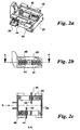
- the displaceably mounted in the housing 4 contact carrier 20 has, according to Fig. 2a - 2c lateral guide webs 38 which, with correspondingly formed structures of the Cooperation housing 4.
- openings 40 and 42 are provided, in which a first and a second contact bridge 44th and 46, while resisting the force of contact springs 48 and 50 within the apertures 40 and 42 are displaceable.
- On the movable contact bridges 44 and 46 each end contact pieces 52 are applied, which, related to the respective contact bridge 44 or 46, in different directions opposite the direction of actuation R show.
- the openings 40 and 42 are in the Carried out that seen from the mounting hole 24 from (Fig. 2c), the Contact bridges 44 and 46 move side by side and transversely to the direction of actuation R extend.
- the position switch further includes a first and a second Terminal block 54 and 56, in a first and second chamber 58 and 60 of a Inner housing 62 are engaged. Together with the connection blocks 54, 56 the inner housing 62 is locked in the housing 4, wherein the inner housing 62nd partially covers the contact carrier 20 and ensures against falling out.
- the Terminal blocks 54 and 56 each consist of an identical base body, in the terminals and fixed contacts are stored.
- the base body 64 of the first connection block 54 carries two first ones Fixed contacts 66 and two terminals 70.
- the terminals 70 are as Tension spring terminals formed and non-positively connected to one of the first fixed contacts 66 connected.
- the first fixed contacts 66 and the terminals 70 are non-positively and positively inserted in the base body 64.
- the main body 64 of the second terminal block 56, two second fixed contacts 68 and two terminals also designed as Glasfederklemmen 70th Auf the second fixed contacts 68 applied fixed contact pieces 53 point in the actuating direction R, whereas applied to the first fixed contacts 66 show fixed contact pieces 53 in the opposite direction.
- the basic body 64 are shown in FIG. 1 in the usual way with elastic first locking means 72nd equipped with corresponding, formed in the chambers 58 and 60 second locking means 74 cooperate.
- first fixed contacts 66 of the first Terminal block 54 form with the mounted in the contact carrier 20 first Contact bridge 44 has a normally open contact.
- the second fixed contacts 68 of the second Terminal block 56 form with the second contact bridge mounted in the contact carrier 20 46 a normally closed contact.
- the terminal blocks 54, 56th and the terminals 70 mounted in these are juxtaposed in a row and perpendicular to the direction of actuation R.
- the terminals 70 are for clamping the inserted through the insertion opening 22
- Connecting cables easily accessible, with already attached connecting cables Do not obstruct the connection of the remaining or additional connecting cables can.
- the terminal blocks 54 and 56 are shown in FIG. 1 each with a mounting hole 24 facing first front end 76 equipped opposite the through the mounting hole 24 formed plane obliquely.
- the first front panel 76 runs in Actuation direction R with increasing distance from the mounting hole 24.
- Die first front fronts 76 of the terminal blocks 54, 56 extend in a plane.
- Im installed Condition adjacent to the first front panels 76 of the terminal blocks 54 and 56 steplessly a second front panel 78, which the inner housing 62 in the direction of Mounting opening 24 limited.
- the second front panel 78 is concave and runs in the direction of actuation R with increasing distance to the mounting opening 24th
- This design of the front fronts 76, 78 has two effects: First enter the conductor ends during insertion of the connecting cables through the insertion opening 22 no inhibitory surfaces or gradations contrary. Instead, glide the conductor ends on the invention shaped front fronts 78 and 76 and be easily bent to the mounting hole 24 out. This can be the Insert conductor ends easily into the terminals 70.
- the other is by the described design of the front fronts 76, 78 between the insertion opening 22 and the terminals 70 a large space has been created. This On the one hand, space makes it easier to connect the connecting cables and on the other hand as storage space for the problem-free accommodation of excess line lengths.
- the third connection block 55 shown in FIG. 5 corresponds in its contact function the first terminal block 54 of FIG. 3.
- the fourth terminal block shown in FIG 57 corresponds in its contact function to the second terminal block 56 of FIG. 4.
- the same elements of Fig. 3 and 5 and of Fig. 4 and 6 are denoted by the same reference numerals busy. For these elements, therefore, to the above description directed.
- the receding first front panel 76 is formed on the main bodies 65 of the third terminal block 55 and the fourth Terminal block 57.
- the receding first front panel 76 is formed on the main bodies 65 of the third terminal block 55 and the fourth Terminal block 57.
- the receding first front panel 76 is formed on the main bodies 65 of the third terminal block 55 and the fourth Terminal block 57.
- the receding first front panel 76 is formed on the main bodies 65 of the third terminal block 55 and the fourth Terminal block 57.
- the receding first front panel 76 is formed on the main bodies 65 of the third terminal block 55 and the fourth Terminal block
- connection technology in a convenient way be chosen or changed.
- the present invention is not limited to the above-described embodiments limited. It is also within the meaning of the invention that the fixed contacts 66, 68 and the terminals 70 or 71 stored in a single terminal block are. Likewise, an inventive position switch only with a contact unit or with more than two, in the sense described adjacent contact units be equipped. For the invention, it is also irrelevant with which Switching characteristic (e.g., creeping, erratic, leading, lagging) the individual Contact units are equipped.
- Switching characteristic e.g., creeping, erratic, leading, lagging
Landscapes
- Push-Button Switches (AREA)
- Switch Cases, Indication, And Locking (AREA)
- Electrophonic Musical Instruments (AREA)
- Fittings On The Vehicle Exterior For Carrying Loads, And Devices For Holding Or Mounting Articles (AREA)
- Switches With Compound Operations (AREA)
- Connections Arranged To Contact A Plurality Of Conductors (AREA)
Description
- Figur 1:
- die auseinander gezogene perspektivische Darstellung eines erfindungsgemäßen Positionsschalters;
- Figur 2a bis 2c:
- die perspektivische Darstellung, eine Seitenansicht und die Schnittdarstellung A-A des Kontaktträgers aus Fig. 1;
- Figur 3:
- die perspektivische Darstellung eines ersten Anschlussblocks aus Fig. 1;
- Figur 4:
- die perspektivische Darstellung eines zweiten Anschlussblocks aus Fig. 1
- Figur 5:
- die perspektivische Darstellung eines dritten Anschlussblocks;
- Figur 6:
- die perspektivische Darstellung eines dritten Anschlussblocks.
Claims (8)
- Positionsschalter mit einem Gehäuse (4) und einem Antrieb (6), der mit einem Betätigungsstößel (8) ins Gehäuse (4) reicht, wobei das Gehäuse (4) eine durch einen Deckel (26) verschließbare, seitliche Montageöffnung (24) sowie eine dem Antrieb (6) gegenüberliegende, in einer der Montageöffnung (24) benachbarten Gehäuseseite ausgebildete Einführöffnung (22) für Anschlussleitungen aufweist und im Gehäuse (4) ein vom Betätigungsstößel (8) in Betätigungsrichtung (R) verschiebbarer Kontaktträger (20) mit Kontaktbrücken (44; 46) gelagert ist, denen jeweils zwei mit Anschlussklemmen (70; 71) verbundene Festkontakte (66; 68) zugeordnet sind, dadurch gekennzeichnet, dass senkrecht zur Betätigungsrichtung (R) sowie parallel zur von der Montageöffnung (24) aufgespannten Ebene sowohl die Kontaktbrücken (44; 46) verlaufen als auch die Anschlussklemmen (70; 71) gereiht sind und dass die Festkontakte (66; 68) und die Anschlussklemmen (70; 71) in wenigstens einem im Gehäuse (4) festgelegten Anschlussblock (54 ... 57) angeordnet sind, dessen erste Vorderfront (76) in Richtung Einführöffnung (22) mit zunehmendem Abstand gegenüber der von der Montageöffnung (24) aufgespannten Ebene verläuft.
- Positionsschalter nach vorstehendem Anspruch, dadurch gekennzeichnet, dass für die jeweils zu einer Kontaktbrücke (44; 46) gehörenden Festkontakte (66; 68) und Anschlussklemmen (70; 71) separate Anschlussblöcke (54, 56; 55; 57) vorgesehen sind.
- Positionsschalter nach vorstehendem Anspruch, dadurch gekennzeichnet, dass die Kontaktbrücken (44; 46) mit den zugehörigen Festkontakten (66; 68) unterschiedliche Kontaktarten bilden.
- Positionsschalter nach einem der vorstehenden Ansprüche, dadurch gekennzeichnet, dass der mindestens eine Anschlussblock (54 ... 57) in ein Innengehäuse (62) eingesetzt ist, das seinerseits im Gehäuse (4) gehaltenen wird und den Kontaktträger (20) sichert.
- Positionsschalter nach vorstehendem Anspruch, dadurch gekennzeichnet, dass die zu dem Innengehäuse (62) gehörende zweite Vorderfront (78) in Richtung Einführöffnung (22) sich im Wesentlichen stufenlos an die erste Vorderfront (76) anschließt und mit zunehmendem Abstand gegenüber der von der Montageöffnung (24) aufgespannten Ebene verläuft.
- Positionsschalter nach einem der Ansprüche 1 bis 5, dadurch gekennzeichnet, dass die Anschlussklemmen (70) als Zugfederklemmen ausgebildet sind.
- Positionsschalter nach einem der Ansprüche 1 bis 6, dadurch gekennzeichnet, dass die Anschlussklemmen (71) als Schraubklemmen ausgebildet sind.
- Positionsschalter nach einem der Ansprüche 1 bis 6, dadurch gekennzeichnet, dass wahlweise wenigsten ein Anschlussblock (54; 56) mit Zugfederklemmen (70) oder wenigstens ein Anschlussblock (55; 57) mit Schraubklemmen (71) im Gehäuse (4) festgelegt ist.
Applications Claiming Priority (2)
| Application Number | Priority Date | Filing Date | Title |
|---|---|---|---|
| DE10244371A DE10244371C1 (de) | 2002-09-24 | 2002-09-24 | Positionsschalter |
| DE10244371 | 2002-09-24 |
Publications (2)
| Publication Number | Publication Date |
|---|---|
| EP1403890A1 EP1403890A1 (de) | 2004-03-31 |
| EP1403890B1 true EP1403890B1 (de) | 2005-11-16 |
Family
ID=29285739
Family Applications (1)
| Application Number | Title | Priority Date | Filing Date |
|---|---|---|---|
| EP03021431A Expired - Lifetime EP1403890B1 (de) | 2002-09-24 | 2003-09-23 | Positionsschalter |
Country Status (3)
| Country | Link |
|---|---|
| EP (1) | EP1403890B1 (de) |
| AT (1) | ATE310314T1 (de) |
| DE (2) | DE10244371C1 (de) |
Families Citing this family (3)
| Publication number | Priority date | Publication date | Assignee | Title |
|---|---|---|---|---|
| GB0414587D0 (en) * | 2004-06-30 | 2004-08-04 | Eja Ltd | Improvements in or relating to switch contacts |
| DE102013103451B4 (de) * | 2012-11-13 | 2016-07-28 | Stego-Holding Gmbh | Türkontaktschalter, insbesondere für Schaltschränke |
| USD737219S1 (en) | 2013-05-14 | 2015-08-25 | Stego-Holding Gmbh | Door contact switch |
Family Cites Families (5)
| Publication number | Priority date | Publication date | Assignee | Title |
|---|---|---|---|---|
| DE908761C (de) * | 1945-01-25 | 1954-04-08 | Siemens Ag | Endschalter fuer Werkzeugmaschinen od. dgl. |
| DE972996C (de) * | 1953-02-14 | 1959-11-12 | Metzenauer & Jung G M B H | Elektrischer Schalter, insbesondere Endschalter fuer elektrische Steuerungen |
| DE3943377C1 (en) * | 1989-12-30 | 1991-02-21 | Kloeckner-Moeller Elektrizitaetsgesellschaft Mbh, 5300 Bonn, De | Locking closure for electrical switching appts. housing - has arresting nose on cover engaging recess in housing and locking part arresting snap coupling |
| DE19856678C2 (de) * | 1998-12-04 | 2002-01-24 | Moeller Gmbh | Elektrische Schaltvorrichtung |
| GB0006482D0 (en) * | 2000-03-20 | 2000-05-10 | Eja Ltd | Contact assembly |
-
2002
- 2002-09-24 DE DE10244371A patent/DE10244371C1/de not_active Expired - Fee Related
-
2003
- 2003-09-23 AT AT03021431T patent/ATE310314T1/de active
- 2003-09-23 EP EP03021431A patent/EP1403890B1/de not_active Expired - Lifetime
- 2003-09-23 DE DE50301659T patent/DE50301659D1/de not_active Expired - Lifetime
Also Published As
| Publication number | Publication date |
|---|---|
| DE50301659D1 (de) | 2005-12-22 |
| EP1403890A1 (de) | 2004-03-31 |
| ATE310314T1 (de) | 2005-12-15 |
| DE10244371C1 (de) | 2003-11-27 |
Similar Documents
| Publication | Publication Date | Title |
|---|---|---|
| EP0899818B1 (de) | Elektrische Anschlussklemme, insbesondere für den Einsatz auf Leiterplatten | |
| DE69703829T2 (de) | Automatische Anschlussklemme und ein elektrisches Gerät ausgerüstet mit einer solchen Klemme | |
| WO2009112263A1 (de) | Schaltbrücke und baueinheit aus mindestens zwei elektrischen reihenklemmen und einer schaltbrücke | |
| DE10103187B4 (de) | Elektrische Klemme | |
| DD292105A5 (de) | Schaltvorrichtung mit geschuetzten unterbrechern | |
| EP2559107B1 (de) | Hauptleiteranschlussklemme | |
| EP0606241A1 (de) | Steckverbinder mit kurzschlussbrücke. | |
| EP1277258A1 (de) | Verbinder für stromschienen | |
| DE1765978B1 (de) | Schaltungsblock zum elektrischen verbinden mittels steck verbindungen von elektrischen schaltungselementen | |
| DE60022798T2 (de) | Elektrischer Verbindungsstecker mit wählbarer Kompatibilität | |
| DE69709533T2 (de) | Verbindungsmodul mit Durchverbindung von Anschlüssen mittels eines oder mehreren beweglichen leitenden Teilen | |
| DE4133092A1 (de) | Mehrpoliger vakuumschalter mit einer polantriebseinheit fuer jede vakuumschaltroehre | |
| DE29505046U1 (de) | Niederspannungs-Schaltgerät mit Berührungsschutz | |
| DE10244371C1 (de) | Positionsschalter | |
| EP0743708B1 (de) | Sammelschienen-Anschlussklemme | |
| DE29508610U1 (de) | Hilfsschalterbaustein schmaler Bauweise | |
| EP1403889B1 (de) | Positionsschalter | |
| DE102008014180A1 (de) | Trennklemme, insbesondere Neutralleiter-Trennklemme | |
| EP0831569A2 (de) | Hilfsschalter | |
| EP1414052B1 (de) | Positionsschalter mit Sprungverhalten | |
| EP1356548A1 (de) | Kontaktvorrichtung zur lösbaren verbindung einer bewegbaren geräteeinheit mit ortsfesten kontaktkörpern | |
| EP1129461B1 (de) | Relais mit koppelelement | |
| DE3011779A1 (de) | Mechanische verriegelungseinrichtung gegen gleichzeitiges einschalten zweier schuetze | |
| EP0862784A1 (de) | Überstromschutzschalter | |
| DE69508199T2 (de) | Kippschalter mit Modulgehäuse |
Legal Events
| Date | Code | Title | Description |
|---|---|---|---|
| PUAI | Public reference made under article 153(3) epc to a published international application that has entered the european phase |
Free format text: ORIGINAL CODE: 0009012 |
|
| AK | Designated contracting states |
Kind code of ref document: A1 Designated state(s): AT BE BG CH CY CZ DE DK EE ES FI FR GB GR HU IE IT LI LU MC NL PT RO SE SI SK TR |
|
| AX | Request for extension of the european patent |
Extension state: AL LT LV MK |
|
| 17P | Request for examination filed |
Effective date: 20040907 |
|
| 17Q | First examination report despatched |
Effective date: 20041025 |
|
| AKX | Designation fees paid |
Designated state(s): AT DE FR IT NL |
|
| GRAP | Despatch of communication of intention to grant a patent |
Free format text: ORIGINAL CODE: EPIDOSNIGR1 |
|
| RIN1 | Information on inventor provided before grant (corrected) |
Inventor name: BREUCH, PETER Inventor name: BRUCHSCHMIDT, FRANK |
|
| GRAS | Grant fee paid |
Free format text: ORIGINAL CODE: EPIDOSNIGR3 |
|
| GRAA | (expected) grant |
Free format text: ORIGINAL CODE: 0009210 |
|
| AK | Designated contracting states |
Kind code of ref document: B1 Designated state(s): AT DE FR IT NL |
|
| REF | Corresponds to: |
Ref document number: 50301659 Country of ref document: DE Date of ref document: 20051222 Kind code of ref document: P |
|
| ET | Fr: translation filed | ||
| PLBE | No opposition filed within time limit |
Free format text: ORIGINAL CODE: 0009261 |
|
| STAA | Information on the status of an ep patent application or granted ep patent |
Free format text: STATUS: NO OPPOSITION FILED WITHIN TIME LIMIT |
|
| 26N | No opposition filed |
Effective date: 20060817 |
|
| REG | Reference to a national code |
Ref country code: FR Ref legal event code: PLFP Year of fee payment: 13 |
|
| REG | Reference to a national code |
Ref country code: FR Ref legal event code: PLFP Year of fee payment: 14 |
|
| REG | Reference to a national code |
Ref country code: FR Ref legal event code: PLFP Year of fee payment: 15 |
|
| REG | Reference to a national code |
Ref country code: FR Ref legal event code: PLFP Year of fee payment: 16 |
|
| PGFP | Annual fee paid to national office [announced via postgrant information from national office to epo] |
Ref country code: AT Payment date: 20180822 Year of fee payment: 16 |
|
| REG | Reference to a national code |
Ref country code: AT Ref legal event code: MM01 Ref document number: 310314 Country of ref document: AT Kind code of ref document: T Effective date: 20190923 |
|
| PG25 | Lapsed in a contracting state [announced via postgrant information from national office to epo] |
Ref country code: AT Free format text: LAPSE BECAUSE OF NON-PAYMENT OF DUE FEES Effective date: 20190923 |
|
| PGFP | Annual fee paid to national office [announced via postgrant information from national office to epo] |
Ref country code: NL Payment date: 20220819 Year of fee payment: 20 |
|
| PGFP | Annual fee paid to national office [announced via postgrant information from national office to epo] |
Ref country code: IT Payment date: 20220825 Year of fee payment: 20 Ref country code: DE Payment date: 20220616 Year of fee payment: 20 |
|
| PGFP | Annual fee paid to national office [announced via postgrant information from national office to epo] |
Ref country code: FR Payment date: 20220819 Year of fee payment: 20 |
|
| P01 | Opt-out of the competence of the unified patent court (upc) registered |
Effective date: 20230521 |
|
| REG | Reference to a national code |
Ref country code: DE Ref legal event code: R071 Ref document number: 50301659 Country of ref document: DE |
|
| REG | Reference to a national code |
Ref country code: NL Ref legal event code: MK Effective date: 20230922 |