EP1404004B1 - Elektromotor - Google Patents
Elektromotor Download PDFInfo
- Publication number
- EP1404004B1 EP1404004B1 EP03021572.7A EP03021572A EP1404004B1 EP 1404004 B1 EP1404004 B1 EP 1404004B1 EP 03021572 A EP03021572 A EP 03021572A EP 1404004 B1 EP1404004 B1 EP 1404004B1
- Authority
- EP
- European Patent Office
- Prior art keywords
- rotor
- magnetic field
- field producing
- producing elements
- edges
- Prior art date
- Legal status (The legal status is an assumption and is not a legal conclusion. Google has not performed a legal analysis and makes no representation as to the accuracy of the status listed.)
- Expired - Lifetime
Links
Images

Classifications
-
- H—ELECTRICITY
- H02—GENERATION; CONVERSION OR DISTRIBUTION OF ELECTRIC POWER
- H02K—DYNAMO-ELECTRIC MACHINES
- H02K1/00—Details of the magnetic circuit
- H02K1/06—Details of the magnetic circuit characterised by the shape, form or construction
- H02K1/22—Rotating parts of the magnetic circuit
- H02K1/27—Rotor cores with permanent magnets
- H02K1/2786—Outer rotors
- H02K1/2787—Outer rotors the magnetisation axis of the magnets being perpendicular to the rotor axis
- H02K1/2789—Outer rotors the magnetisation axis of the magnets being perpendicular to the rotor axis the rotor consisting of two or more circumferentially positioned magnets
- H02K1/2791—Surface mounted magnets; Inset magnets
-
- H—ELECTRICITY
- H02—GENERATION; CONVERSION OR DISTRIBUTION OF ELECTRIC POWER
- H02K—DYNAMO-ELECTRIC MACHINES
- H02K1/00—Details of the magnetic circuit
- H02K1/06—Details of the magnetic circuit characterised by the shape, form or construction
- H02K1/22—Rotating parts of the magnetic circuit
- H02K1/28—Means for mounting or fastening rotating magnetic parts on to, or to, the rotor structures
Definitions
- the present invention relates to an electric motor, in particular to means of mounting magnetic field producing elements on an external rotor of an electric motor.
- a further disadvantage of rotors assembled in this way is that when used in an electrically commutated motor such as a brushless DC motor, the torque exerted on the rotor as a result of the magnetic field generated by coils in the stator pulses. As a result, the rotor tends to vibrate whilst rotating and vibration pulses are set-up. This causes the motor to be undesirably noisy, and is a particular problem when the motor is used in applications in which the rotor rotates at relatively high speeds, for example when the motor is used to drive a steering pump.
- an electric motor including a rotor with a generally cylindrical rotor wall and a plurality of magnetic field producing elements mounted on an inside surface of the rotor wall, the rotor being mounted for rotation around a central stator, wherein the magnetic field producing elements are mounted on the rotor wall by means of a plurality of resilient retaining members, at least one resilient retaining member being located between and engaging with edges of two adjacent magnetic field producing elements, the edges of the magnetic field producing elements extending generally parallel to an axis of rotation of the rotor, wherein each resilient retaining member includes a first and a second portion each with a first edge and an opposite second edge, the two portions being joined along their first edges and inclined relative to one another at an angle of between 0 and 90°, characterised in that the resilient retaining members are elastically deformed so as to exert a retaining force on the magnetic field producing elements, and in that each resilient retaining member is arranged with the second edges of the first and second portions directly adjacent to the rotor wall
- the magnets may quickly and easily be mounted on the rotor wall.
- shaping the edges of the magnets to conform to the shape of the resilient retaining member permits a greater area of the edges of the elements to engage with the retaining member, and hence may further assist in retaining the magnetic field producing elements on the rotor wall.
- the electric motor is preferably an electrically commutated motor such as a brushless DC motor.
- any vibration pulses such as those produced due to torque pulses produced in an electrically commutated motor, tend to be damped, and thus a motor having a rotor according to the first aspect of the invention tends to be less noisy in use than comparable prior art electric motors.
- the magnetic field producing elements are permanent magnets.
- each resilient retaining member is preferably elongate and is preferably arranged with its longitudinal axis generally parallel to the longitudinal axes of the magnetic field producing elements.
- each resilient retaining member preferably extends along substantially the entire length of the magnetic field producing elements.
- a method of assembling a rotor for an electric motor the rotor being adapted in use to rotate about an axis of rotation, the method including the steps of positioning a plurality of magnetic field producing elements against an inside surface of a cylindrical wall of the rotor, inserting a resilient retaining member having a first and second portion, each with a first edge and an opposite second edge, the first and second portions being joined along their first edges and inclined relative to one another at an angle of between 0 and 90°, between edges of each pair of adjacent magnetic field producing elements which extend generally parallel to the axis of rotation of the rotor, each resilient retaining member being elastically deformed during insertion such that once in place it exerts a retaining force on the magnetic field producing elements, and being arranged with the second edges of the first and second portions directly adjacent to the rotor wall.
- a rotor 10 and a stator 12 for an electric motor preferably for an electrically commutated motor such as a brushless DC motor.
- Both the rotor 10 and stator 12 are generally cylindrical, and the rotor 10 is arranged concentrically around the stator 12.
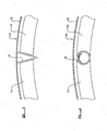
- the rotor 10 includes a generally cylindrical rotor wall 13, which is mounted for rotation about its longitudinal axis A by conventional means (not shown), and a plurality of magnetic field producing elements 14, which in this example are permanent magnets 14, mounted around the entire circumference and on an inside surface of the rotor wall 13.
- Each magnet 14 is an elongate and is arranged with its longitudinal axis parallel to the longitudinal axis A of the rotor 10.
- the transverse cross-section of each magnet 14 has the shape of a segment of an annulus, and thus each magnet 14 has two opposite curved faces and two opposite planar edges.
- each retaining bar 16' has a T-shaped transverse cross-section, and has a stem 16'a which extends between two adjacent magnets 14 radially inwardly of the rotor wall 13, and a head 16'b which engages with a top surface of an edge of each magnet to retain the magnets 14 with respect to the rotor wall 13.
- each retaining bar 16' is attached to the rotor wall 13 by welding or other such method, and therefore attaching the retaining bars 16' on the rotor wall 13 is time consuming. Moreover, care must be taken when attaching the retaining bars 16' to the rotor wall 13, to ensure that the retaining bars 16' clamp down on the magnets tightly enough completely to prevent movement of the magnets 14 with respect to the rotor wall 13.
- an electrically commutated motor such as a brushless DC motor
- pulses in the torque exerted on the rotor 10 by coils within the stator 12 cause the rotor 10 to vibrate and vibration pulses to be set up, which significantly increases the noise generated by the electric motor.
- the magnets 14 are mounted on the rotor wall 13 by means of a plurality of resilient retaining members 16, there being at least one retaining member 16 between each pair of adjacent magnets.
- Each retaining member 16 is elastically deformed so as to exert a retaining force on the magnets 14.
- Each retaining member 16 is an elongate element with a V-shaped transverse cross-section.
- each retaining member 16 has a first and a second portion each with a first edge and an opposite second edge, the two portions being joined along their first edges and inclined relative to one another, in this example at an angle of approximately 30° although another angle between 0° and 90° may be adopted.
- the retaining members 16 are made from a material such as spring steel.
- Each retaining member 16 is arranged between two adjacent magnets 14 with a longitudinal axis generally parallel to the longitudinal axis A of the rotor wall 13, with the second edges of the first and second portions adjacent to the rotor wall 13, and the first portion engaging with the edge of one magnet 14 and the second portion engaging with the edge of the adjacent magnet 14. In this example, each retaining member 16 extends along substantially the entire length of the magnets 14.
- the size and number of magnets 14 are such that the gap between adjacent magnets is too small to receive the retaining member 16 without the retaining member 16 being elastically deformed to bring the first and second portions closer together.
- the retaining members are deformed prior to or during insertion between the magnets 14, and then released when in place between adjacent magnets, whereupon they expand and the first and second portions of the retaining member 16 push outwardly against the magnets 14 and hence exert a retaining force on the magnets 14.
- this retaining force is sufficient to retain the magnets 14 in position around the rotor wall 13.
- each retaining member 16 In order to increase the area of contact between each retaining member 16 and the adjacent magnets 14, it is possible to shape the edges of the magnets 14 to conform with the shape of retaining members 16. This may assist in retaining the magnets 14 against the rotor wall 13.
- the edges of the magnets 14 may be inclined so that they do not lie radially with respect to the rotor wall 13, but instead lie substantially parallel to the first and second portions of the retaining members 16.
- the edges of the magnets 14 are each provided with a generally semicircular recess which is adapted to receive part of a retaining member 16. This is not, however, necessary, and magnets 14 of the configurations shown in Figures 2 and 3 may be used with a retaining member 16 having a generally circular cross-section.
- each retaining member 16 extends along substantially the entire length of the magnets 14, the retaining members 16 may be shorter than the magnets 14, provided they supply sufficient retaining force to retain the magnets 14 on the rotor wall 13. Alternatively, if desired, two or more short retaining members 16 may be provided between each pair of adjacent magnets 14.
- the magnetic field producing elements 14 need not be permenant magnets. They may instead include an element which can be induced to produce a magnetic field, such as a magnetizable element or electrically conducting coil, in which case, the rotor 10 may be used in a switched reluctance motor.
- the rotor wall 13 typically is made from sheet metal, but may instead be made from a composite material comprising a viscoelastic material sandwiched between two sheets of metal. Such a material is commercially available under the name BONDAL® .
- BONDAL® a composite material comprising a viscoelastic material sandwiched between two sheets of metal.
- BONDAL® a material comprising a viscoelastic material sandwiched between two sheets of metal.
- BONDAL® a material comprising a viscoelastic material sandwiched between two sheets of metal.
- BONDAL® a material comprising a viscoelastic material sandwiched between two sheets of metal.
- BONDAL® a material comprising a viscoelastic material sandwiched between two sheets of metal.
- the use of such a material is particularly advantageous in an electric motor according to the invention, as it further reduces the vibration noise produced by the rotor 10 when in use. It is believed that the frequency of vibrations generated by movement of the
- the invention is particularly useful when the motor is used in applications in which the rotor must rotate relatively fast, for example when the motor is used to drive a steering pump in a motor vehicle.
Landscapes
- Engineering & Computer Science (AREA)
- Power Engineering (AREA)
- Permanent Field Magnets Of Synchronous Machinery (AREA)
- Iron Core Of Rotating Electric Machines (AREA)
Claims (7)
- Elektromotor beinhaltend einen Rotor (10) mit einer allgemein zylindrischen Rotorwand (13) und einer Mehrzahl von magnetfelderzeugenden Elementen (14), die auf einer Innenoberfläche der Rotorwand (13) montiert sind, wobei der Rotor (10) für die Drehung um einen mittigen Stator (12) herum montiert ist, worin die magnetfelderzeugenden Elemente (14) mittels einer Mehrzahl von elastischen Halteelementen (16) auf der Rotorwand (13) montiert sind, wobei sich mindestens ein elastisches Halteelement (16) zwischen Kanten von zwei aneinandergrenzenden magnetfelderzeugenden Elementen (14) befindet und in sie eingreift, wobei besagte Kanten der magnetfelderzeugenden Elemente (14) allgemein parallel zu einer Drehachse (A) des Rotors (10) verlaufen, worin jedes elastische Halteelement (16) einen ersten und einen zweiten Abschnitt jeweils mit einer ersten Kante und einer entgegengesetzten zweiten Kante beinhaltet, wobei die beiden Abschnitte ihre ersten Kanten entlang verbunden und unter einem Winkel zwischen 0 und 90 zueinander geneigt sind, dadurch gekennzeichnet, dass die elastischen Halteelemente (16) elastisch verformt werden, um eine Haltekraft auf die magnetfelderzeugenden Elemente (14) auszuüben, und dadurch, dass jedes elastische Halteelement (16) mit den zweiten Kanten der ersten und zweiten Abschnitte direkt an die Rotorwand (13) angrenzend angeordnet ist, und der erste Abschnitt in ein erstes magnetfelderzeugendes Element (14) eingreift und der zweite Abschnitt in ein zweites angrenzendes magnetfelderzeugendes Element (14) eingreift.
- Elektromotor nach Anspruch 1, worin der Motor ein elektrisch kommutierter Motor ist.
- Elektromotor nach Anspruch 1 oder 2, worin die magnetfelderzeugenden Elemente (14) Permanentmagnete sind.
- Elektromotor nach irgendeinem vorhergehenden Anspruch, worin die magnetfelderzeugenden Elemente (14) länglich und mit ihren Längsachsen allgemein parallel zur Drehachse (A) der Rotorwand (13) angeordnet sind.
- Elektromotor nach Anspruch 4, worin jedes elastische Halteelement (16) länglich ist und mit seiner Längsachse allgemein parallel zu den Längsachsen der magnetfelderzeugenden Elemente (14) angeordnet ist.
- Elektromotor nach Anspruch 5, worin jedes elastische Halteelement (16) im Wesentlichen die gesamte Länge der magnetfelderzeugenden Elemente (14) entlang verläuft.
- Verfahren zum Montieren eines Rotors (10) für einen Elektromotor, wobei der Rotor (10) dafür ausgelegt ist, sich bei Gebrauch um eine Drehachse (A) herum zu drehen, wobei das Verfahren die Schritte des Positionierens einer Mehrzahl von magnetfelderzeugenden Elemente (14) gegen eine Innenoberfläche einer zylindrischen Wand des Rotors (10) und des Einfügens eines elastischen Halteelements (16) mit einem ersten und zweiten Abschnitt jeweils mit einer ersten Kante und einer entgegengesetzten zweiten Kante beinhaltet, wobei die ersten und zweiten Abschnitte ihre ersten Kanten entlang verbunden und unter einem Winkel zwischen 0 und 90 ° zueinander geneigt sind, zwischen Kanten jedes Paars von aneinandergrenzenden magnetfelderzeugenden (14) Elementen, die allgemein parallel zur Drehachse (A) des Rotors (10) verlaufen, wobei jedes elastische Halteelement (16) während des Einfügens elastisch verformt wird, sodass es, wenn in Position, eine Haltekraft auf die magnetfelderzeugenden Elemente (14) ausübt, und mit den zweiten Kanten der ersten und zweiten Abschnitte direkt an die Rotorwand angrenzend angeordnet ist.
Applications Claiming Priority (2)
| Application Number | Priority Date | Filing Date | Title |
|---|---|---|---|
| GB0222394 | 2002-09-27 | ||
| GB0222394A GB2393583B (en) | 2002-09-27 | 2002-09-27 | Electric motor |
Publications (3)
| Publication Number | Publication Date |
|---|---|
| EP1404004A1 EP1404004A1 (de) | 2004-03-31 |
| EP1404004B1 true EP1404004B1 (de) | 2015-09-02 |
| EP1404004B8 EP1404004B8 (de) | 2015-10-21 |
Family
ID=9944829
Family Applications (1)
| Application Number | Title | Priority Date | Filing Date |
|---|---|---|---|
| EP03021572.7A Expired - Lifetime EP1404004B8 (de) | 2002-09-27 | 2003-09-24 | Elektromotor |
Country Status (3)
| Country | Link |
|---|---|
| US (1) | US6844646B1 (de) |
| EP (1) | EP1404004B8 (de) |
| GB (1) | GB2393583B (de) |
Families Citing this family (14)
| Publication number | Priority date | Publication date | Assignee | Title |
|---|---|---|---|---|
| EP1780870B1 (de) * | 2004-07-16 | 2018-09-05 | Mitsuba Corporation | Magnetfixierungsstruktur für eine elektrische drehmaschine |
| US20060238054A1 (en) * | 2005-04-26 | 2006-10-26 | Bison Gear & Engineering Corp. | Magnet retainer clip for permanent magnet electric motors |
| DE502005010177D1 (de) * | 2005-07-29 | 2010-10-14 | Siemens Ag | Permanentmagnetrotor für eine bürstenlose elektrische Maschine |
| US20070138891A1 (en) * | 2005-12-19 | 2007-06-21 | Emerson Electric Co. | Magnet retention and positioning sleeve for surface mounted rotor assemblies |
| DE102008017276A1 (de) | 2008-04-04 | 2009-10-15 | Danfoss Compressors Gmbh | Rotor für einen elektrischen Antriebsmotor eines Kältemittelkompressors |
| CN101752920A (zh) * | 2008-12-03 | 2010-06-23 | 中山大洋电机股份有限公司 | 一种直驱电机的外转子结构及其制造方法 |
| DE102009042607A1 (de) * | 2009-09-23 | 2011-03-24 | Siemens Aktiengesellschaft | Elektrische Maschine und Rotor für eine elektrische Maschine |
| US20120025655A1 (en) * | 2010-07-29 | 2012-02-02 | System General Corporation | Motor rotor and motor having the motor rotor |
| DE102011087014A1 (de) * | 2011-11-24 | 2013-05-29 | Siemens Aktiengesellschaft | Rotor für eine Elektromaschine |
| DE102013202137A1 (de) * | 2013-02-08 | 2014-08-14 | Robert Bosch Gmbh | Läuferanordnung für eine elektrische Maschine |
| DE102013206438A1 (de) * | 2013-04-11 | 2014-10-16 | Bühler Motor GmbH | Permanentmagnetrotor für einen elektronisch kommutierten Gleichstrommotor |
| CN103312067B (zh) * | 2013-05-23 | 2016-04-20 | 新誉集团有限公司 | 一种外转子永磁发电机磁极结构及装配方法 |
| DE102018204876A1 (de) | 2018-03-29 | 2019-10-02 | Thyssenkrupp Ag | Elektromotor mit geschrägtem Stator und/oder Rotor enthaltend mindestens eine Schicht eines Verbundwerkstoffs |
| US12149127B2 (en) * | 2020-12-04 | 2024-11-19 | Aurora Flight Sciences Corporation | Rotor for electric motor |
Family Cites Families (15)
| Publication number | Priority date | Publication date | Assignee | Title |
|---|---|---|---|---|
| US3663850A (en) * | 1970-08-03 | 1972-05-16 | Phelon Co Inc | Field means for a dynamoelectric machine, magnet preassembly for use therein |
| US3727302A (en) * | 1970-08-03 | 1973-04-17 | Phelon Co Inc | Method of making an annular assembly of magnets for use as the field of a dynamoelectric machine |
| US4012651A (en) * | 1974-12-20 | 1977-03-15 | R. E. Phelon Company, Inc. | Permanent magnet field means for dynamo-electric machines |
| FR2386183A1 (fr) | 1977-03-29 | 1978-10-27 | Novi Pb Sa | Rotor de volant magnetique multipolaire et son mode de montage |
| JPS589500Y2 (ja) * | 1977-06-24 | 1983-02-21 | 株式会社デンソー | 磁石発電機の回転子 |
| DE3105602A1 (de) * | 1981-02-16 | 1982-09-09 | Siemens AG, 1000 Berlin und 8000 München | Staender fuer eine dauermagneterregte elektrische maschine |
| US4636107A (en) * | 1982-03-30 | 1987-01-13 | Plus Manufacturing Co., Inc. | Reformed in place resilient retention springs |
| GB2123318A (en) * | 1982-07-08 | 1984-02-01 | Distillers Company The | Stators for electric motors |
| JPS6142251A (ja) * | 1984-08-03 | 1986-02-28 | Hitachi Ltd | 磁石発電機の回転子 |
| GB2191638B (en) * | 1986-06-14 | 1990-12-19 | Dobson Park Ind | Magnet assemblies |
| JPS63134585U (de) * | 1987-02-23 | 1988-09-02 | ||
| DE3726413A1 (de) * | 1987-08-07 | 1989-02-16 | Siemens Ag | Elektronisch kommutierter gleichstrommotor mit fixiereinrichtung zum festlegen der permanentmagnete |
| FR2734958B1 (fr) * | 1995-06-02 | 1997-07-04 | Ugimag Sa | Dispositif de fixation d'aimants sur culasse de stator ou de rotor de moteurs electriques |
| JP3417332B2 (ja) * | 1999-03-12 | 2003-06-16 | 株式会社デンソー | 直流モータ |
| DE10004703A1 (de) * | 2000-02-03 | 2001-08-23 | Bosch Gmbh Robert | Bügelfeder |
-
2002
- 2002-09-27 GB GB0222394A patent/GB2393583B/en not_active Expired - Fee Related
-
2003
- 2003-09-24 EP EP03021572.7A patent/EP1404004B8/de not_active Expired - Lifetime
- 2003-09-25 US US10/672,930 patent/US6844646B1/en not_active Expired - Fee Related
Also Published As
| Publication number | Publication date |
|---|---|
| GB0222394D0 (en) | 2002-11-06 |
| US6844646B1 (en) | 2005-01-18 |
| GB2393583A (en) | 2004-03-31 |
| EP1404004B8 (de) | 2015-10-21 |
| EP1404004A1 (de) | 2004-03-31 |
| GB2393583B (en) | 2006-03-22 |
Similar Documents
| Publication | Publication Date | Title |
|---|---|---|
| EP1404004B1 (de) | Elektromotor | |
| JP4815967B2 (ja) | 永久磁石式回転電機 | |
| CN1625826B (zh) | 用于电机的转子 | |
| US6408502B1 (en) | Method for a resilient rotor core assembly | |
| US20090289522A1 (en) | Electric Motor and Method for Manufacturing an Electric Motor for a Motor Vehicle Actuator Drive | |
| CN107528396B (zh) | 转子构件、转子以及电动机 | |
| JP2003513597A (ja) | 電気機械 | |
| US20020135244A1 (en) | Brushless D.C. motor | |
| JP2002191143A (ja) | 永久磁石式同期モータとそのモータを備えた自動車 | |
| JP2002345187A (ja) | 永久磁石電気機械 | |
| EP1347561A1 (de) | Linearmotor mit Aufhebung der magnetischen Anziehungskräfte | |
| CN103843230A (zh) | 具有沿径向安装的永久磁体的转子或定子 | |
| KR20060013566A (ko) | 전기 모터의 인덕터 실린더 헤드 내부에 영구자석을고정하는 장치 | |
| JP2006034024A (ja) | 回転電気機械の永久磁石式回転子 | |
| US9673670B2 (en) | Method for producing a rotor and electric machine having a rotor | |
| JPH10178751A (ja) | 電動機 | |
| JP2019047630A (ja) | 回転電機 | |
| JP4003694B2 (ja) | マグネット型モータの製造方法 | |
| JP2012244671A (ja) | アキシャルギャップモータのロータ | |
| JPH08205499A (ja) | 同期電動機 | |
| JP2005278268A (ja) | 永久磁石式モータ | |
| US5929551A (en) | Rotor section containment with steel punched star | |
| KR20070066089A (ko) | 영구자석 및 로터 코어 고정용 고정판이 구비된 영구자석형직류전동기 | |
| CN110943583B (zh) | 制造感应转子的方法 | |
| JPWO2006114890A1 (ja) | アウタロータ型モータのステータ |
Legal Events
| Date | Code | Title | Description |
|---|---|---|---|
| PUAI | Public reference made under article 153(3) epc to a published international application that has entered the european phase |
Free format text: ORIGINAL CODE: 0009012 |
|
| AK | Designated contracting states |
Kind code of ref document: A1 Designated state(s): AT BE BG CH CY CZ DE DK EE ES FI FR GB GR HU IE IT LI LU MC NL PT RO SE SI SK TR |
|
| AX | Request for extension of the european patent |
Extension state: AL LT LV MK |
|
| 17P | Request for examination filed |
Effective date: 20040917 |
|
| AKX | Designation fees paid |
Designated state(s): DE FR GB IT |
|
| 17Q | First examination report despatched |
Effective date: 20060619 |
|
| RAP1 | Party data changed (applicant data changed or rights of an application transferred) |
Owner name: BUEHLER MOTOR GMBH |
|
| GRAP | Despatch of communication of intention to grant a patent |
Free format text: ORIGINAL CODE: EPIDOSNIGR1 |
|
| INTG | Intention to grant announced |
Effective date: 20150521 |
|
| GRAS | Grant fee paid |
Free format text: ORIGINAL CODE: EPIDOSNIGR3 |
|
| GRAA | (expected) grant |
Free format text: ORIGINAL CODE: 0009210 |
|
| REG | Reference to a national code |
Ref country code: FR Ref legal event code: PLFP Year of fee payment: 13 |
|
| AK | Designated contracting states |
Kind code of ref document: B1 Designated state(s): DE FR GB IT |
|
| REG | Reference to a national code |
Ref country code: GB Ref legal event code: FG4D |
|
| RBV | Designated contracting states (corrected) |
Designated state(s): DE FR IT |
|
| REG | Reference to a national code |
Ref country code: DE Ref legal event code: R096 Ref document number: 60347980 Country of ref document: DE |
|
| PGFP | Annual fee paid to national office [announced via postgrant information from national office to epo] |
Ref country code: DE Payment date: 20150911 Year of fee payment: 13 |
|
| PGFP | Annual fee paid to national office [announced via postgrant information from national office to epo] |
Ref country code: FR Payment date: 20150825 Year of fee payment: 13 |
|
| REG | Reference to a national code |
Ref country code: DE Ref legal event code: R082 Ref document number: 60347980 Country of ref document: DE |
|
| PGFP | Annual fee paid to national office [announced via postgrant information from national office to epo] |
Ref country code: IT Payment date: 20151130 Year of fee payment: 13 |
|
| REG | Reference to a national code |
Ref country code: DE Ref legal event code: R097 Ref document number: 60347980 Country of ref document: DE |
|
| PLBE | No opposition filed within time limit |
Free format text: ORIGINAL CODE: 0009261 |
|
| STAA | Information on the status of an ep patent application or granted ep patent |
Free format text: STATUS: NO OPPOSITION FILED WITHIN TIME LIMIT |
|
| 26N | No opposition filed |
Effective date: 20160603 |
|
| REG | Reference to a national code |
Ref country code: DE Ref legal event code: R119 Ref document number: 60347980 Country of ref document: DE |
|
| REG | Reference to a national code |
Ref country code: FR Ref legal event code: ST Effective date: 20170531 |
|
| PG25 | Lapsed in a contracting state [announced via postgrant information from national office to epo] |
Ref country code: FR Free format text: LAPSE BECAUSE OF NON-PAYMENT OF DUE FEES Effective date: 20160930 Ref country code: DE Free format text: LAPSE BECAUSE OF NON-PAYMENT OF DUE FEES Effective date: 20170401 |
|
| PG25 | Lapsed in a contracting state [announced via postgrant information from national office to epo] |
Ref country code: IT Free format text: LAPSE BECAUSE OF NON-PAYMENT OF DUE FEES Effective date: 20160924 |