EP1404154A1 - Magnetisches Heizgerät - Google Patents
Magnetisches Heizgerät Download PDFInfo
- Publication number
- EP1404154A1 EP1404154A1 EP20020102387 EP02102387A EP1404154A1 EP 1404154 A1 EP1404154 A1 EP 1404154A1 EP 20020102387 EP20020102387 EP 20020102387 EP 02102387 A EP02102387 A EP 02102387A EP 1404154 A1 EP1404154 A1 EP 1404154A1
- Authority
- EP
- European Patent Office
- Prior art keywords
- magnetic
- magnetic field
- heating
- free ends
- plane
- Prior art date
- Legal status (The legal status is an assumption and is not a legal conclusion. Google has not performed a legal analysis and makes no representation as to the accuracy of the status listed.)
- Granted
Links
Images


Classifications
-
- H—ELECTRICITY
- H05—ELECTRIC TECHNIQUES NOT OTHERWISE PROVIDED FOR
- H05B—ELECTRIC HEATING; ELECTRIC LIGHT SOURCES NOT OTHERWISE PROVIDED FOR; CIRCUIT ARRANGEMENTS FOR ELECTRIC LIGHT SOURCES, IN GENERAL
- H05B6/00—Heating by electric, magnetic or electromagnetic fields
- H05B6/02—Induction heating
- H05B6/10—Induction heating apparatus, other than furnaces, for specific applications
- H05B6/101—Induction heating apparatus, other than furnaces, for specific applications for local heating of metal pieces
-
- H—ELECTRICITY
- H05—ELECTRIC TECHNIQUES NOT OTHERWISE PROVIDED FOR
- H05B—ELECTRIC HEATING; ELECTRIC LIGHT SOURCES NOT OTHERWISE PROVIDED FOR; CIRCUIT ARRANGEMENTS FOR ELECTRIC LIGHT SOURCES, IN GENERAL
- H05B6/00—Heating by electric, magnetic or electromagnetic fields
- H05B6/02—Induction heating
- H05B6/06—Control, e.g. of temperature, of power
- H05B6/062—Control, e.g. of temperature, of power for cooking plates or the like
- H05B6/065—Control, e.g. of temperature, of power for cooking plates or the like using coordinated control of multiple induction coils
-
- H—ELECTRICITY
- H05—ELECTRIC TECHNIQUES NOT OTHERWISE PROVIDED FOR
- H05B—ELECTRIC HEATING; ELECTRIC LIGHT SOURCES NOT OTHERWISE PROVIDED FOR; CIRCUIT ARRANGEMENTS FOR ELECTRIC LIGHT SOURCES, IN GENERAL
- H05B6/00—Heating by electric, magnetic or electromagnetic fields
- H05B6/02—Induction heating
- H05B6/10—Induction heating apparatus, other than furnaces, for specific applications
- H05B6/12—Cooking devices
- H05B6/1209—Cooking devices induction cooking plates or the like and devices to be used in combination with them
- H05B6/1245—Cooking devices induction cooking plates or the like and devices to be used in combination with them with special coil arrangements
- H05B6/1254—Cooking devices induction cooking plates or the like and devices to be used in combination with them with special coil arrangements using conductive pieces to direct the induced magnetic field
-
- H—ELECTRICITY
- H05—ELECTRIC TECHNIQUES NOT OTHERWISE PROVIDED FOR
- H05B—ELECTRIC HEATING; ELECTRIC LIGHT SOURCES NOT OTHERWISE PROVIDED FOR; CIRCUIT ARRANGEMENTS FOR ELECTRIC LIGHT SOURCES, IN GENERAL
- H05B6/00—Heating by electric, magnetic or electromagnetic fields
- H05B6/02—Induction heating
- H05B6/10—Induction heating apparatus, other than furnaces, for specific applications
- H05B6/12—Cooking devices
- H05B6/1209—Cooking devices induction cooking plates or the like and devices to be used in combination with them
- H05B6/1245—Cooking devices induction cooking plates or the like and devices to be used in combination with them with special coil arrangements
- H05B6/1272—Cooking devices induction cooking plates or the like and devices to be used in combination with them with special coil arrangements with more than one coil or coil segment per heating zone
-
- H—ELECTRICITY
- H05—ELECTRIC TECHNIQUES NOT OTHERWISE PROVIDED FOR
- H05B—ELECTRIC HEATING; ELECTRIC LIGHT SOURCES NOT OTHERWISE PROVIDED FOR; CIRCUIT ARRANGEMENTS FOR ELECTRIC LIGHT SOURCES, IN GENERAL
- H05B2213/00—Aspects relating both to resistive heating and to induction heating, covered by H05B3/00 and H05B6/00
- H05B2213/03—Heating plates made out of a matrix of heating elements that can define heating areas adapted to cookware randomly placed on the heating plate
-
- Y—GENERAL TAGGING OF NEW TECHNOLOGICAL DEVELOPMENTS; GENERAL TAGGING OF CROSS-SECTIONAL TECHNOLOGIES SPANNING OVER SEVERAL SECTIONS OF THE IPC; TECHNICAL SUBJECTS COVERED BY FORMER USPC CROSS-REFERENCE ART COLLECTIONS [XRACs] AND DIGESTS
- Y02—TECHNOLOGIES OR APPLICATIONS FOR MITIGATION OR ADAPTATION AGAINST CLIMATE CHANGE
- Y02B—CLIMATE CHANGE MITIGATION TECHNOLOGIES RELATED TO BUILDINGS, e.g. HOUSING, HOUSE APPLIANCES OR RELATED END-USER APPLICATIONS
- Y02B40/00—Technologies aiming at improving the efficiency of home appliances, e.g. induction cooking or efficient technologies for refrigerators, freezers or dish washers
Definitions
- the present invention relates to a heating device according to the preamble of the independent claims and comprises generally a novel device for heating metallic parts, and also, more specifically, a magnetic heating device for heating a heating means.
- Convection heating can be used which may include direct flame, immersion, radiation, electrical resistance where the heating of the metal is caused by the flow of the electricity and heat may be created by mechanical stresses or friction. Included among these has been induction heating where the heating is caused by use of magnetic fields.
- induction heating where the heating is caused by use of magnetic fields.
- a metal workpiece is placed in a coil supplied with alternating current and the workpiece and the coil are linked by a magnetic field so that an induced current is present in the metal. This induced current heats the metal because of resistive losses similar to any electrical resistance heating.
- the coil normally becomes heated and must be cooled in order to make the heating of the workpiece as effective as possible.
- the density of the induced current is greatest at the surface of the workpiece and reduces as the distance from the surface increases. This phenomenon is known as the skin effect and is important because it is only within this depth that the majority of the total energy is induced and is available for heating. Typical maximum skin depths are three to four inches (8-10 cm) for low frequency applications. In all induction heating applications, the heating begins at the surface due to the eddy currents and conduction carries heat into the body of the workpiece.
- transfer flux heating Another method of heating metal parts using magnetic fields is called transfer flux heating. This method is commonly used in heating relatively thin strips of metal and transfers flux heat by a rearrangement of the induction coils so that the magnetic flux passes through the workpiece at right angles to the workpiece rather than around the workpiece as in normal induction heating. Magnetic flux passing through the workpiece induces flux lines to circulate in the plane of the strip and this results in the same eddy current loss and heating of the workpiece.
- US-5,025,124 is disclosed an electromagnetic device for heating metal elements where the heating is accomplished by utilizing a magnetic loop for creating a high density alternating magnetic field in a metal part to be heated.
- the US-patent is based on the knowledge of replacing, in a magnetic loop, a part of the magnetic core by the metal part to be heated.
- the metal part is placed between the magnetic poles and may not be used in applications where it is desired to heat the metal parts from one side.
- the object of the present invention is to achieve a heating device that enables heating of metal parts, e.g. planar metal sheets, from one side.
- the present invention is based on a principle where the metal part is heated from one side by turning the magnetic field 90 degrees with regard to the magnetic field generated by the magnetic field generator.
- both paramagnetic and ferromagnetic may be combined in the same heating application.
- the heating device is a separate unit adapted to be held or fasten against, in a permanent or provisional way, a ferromagnetic material to be heated.
- the heating device includes a heating means, preferably in the form of planar sheets, permanently fasten to the heating means.
- the present invention has solved many problems of the technique used today, e.g. high-energy consumption due to indirect heating via electrical heating wires.
- Another drawback with many prior art methods is the uneven heating independent of the used heating method.
- the present invention solves the problem with uneven heating by controlling the magnetic fields in a symmetrical fashion over the whole metal surface to be heated.
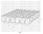
- FIG 1 is shown a schematic illustration of a heating device including a number of magnetic modules.
- Each magnetic module includes two magnetic field generators.
- Each magnet field generator includes a U-shaped magnetic core 1 provided with two magnetic coils 2.
- Each magnetic field generator has two free ends 6 (only some are indicated in the figure).
- figure 1 is arranged three rows of magnetic modules with four modules in each row.
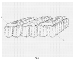
- Figure 2 shows, from below, a schematic illustration of a number of magnetic modules as shown in figure 1.
- Figure 3 shows a cross-sectional view and a view from above of one magnetic module according to present invention.
- a heating means comprising a planar sheet that includes an upper ferromagnetic sheet 5 and a lower paramagnetic sheet 4.
- the magnetic core may, alternatively, have any geometrical form provided that the magnetic core has two free ends in the same plane and that the magnetic core together with the ferromagnetic material to be heated forms a closed magnetic loop.
- a V-shaped core an asymmetrical U-shaped core.
- the magnetic core may consist of laminated silicon sheets, e.g. so called transformer core sheet, or loose powder sintered magnetic material.
- the metal to be heated is placed on or close to the magnetic field generators.
- the magnetic modules are in direct contact to the metal part of ferromagnetic material to be heated.
- an air-gap or a sheet made of a dielectrical material defining a predetermined distance between the magnetic modules and the metal part to be heated.
- the thickness of the air-gap (or the dielectrical sheet) is determined in relation to the intended application of the heating device. Generally, the square of the thickness of the air-gap influences the total thickness of the metal part (the thickness of the metal sheets) up to a maximum total thickness (air-gap and metal part) of 90 mm, given an air-gap of 9 mm.
- an air-gap of 1 or 2 mm was chosen in combination with a ferromagnetic material, e.g. iron, of 4 mm and a paramagnetic material (aluminium) of 2 mm.
- a ferromagnetic material e.g. iron
- a paramagnetic material aluminium
- the metal part to be heated is a ferromagnetic material, e.g. iron, cast iron, magnetic stainless steel and all alloys that include iron.
- the magnetic heating device is a separate unit vis-a-vis the metal part to be heated.
- the heating device then is adapted to be held against, permanently or provisionally fasten, to the metal part to be heated.
- the metal part has the form of a heating means, preferably a planar sheet, permanently arranged on or close to the free ends of the magnetic cores of the magnetic modules.
- a heating means preferably a planar sheet
- This group of embodiments have many different applications, e.g. in frying hob arrangements where the planar sheet of iron is used as a frying surface.
- the defined plane may either be straight, i.e. the free ends in said defined plane are in the same level, or curved, where the curved plane is adapted to the particular application.
- a curved plane may have the shape of a part of a cylindrical wall or be a part of a spherical wall. Other geometrical shapes are naturally possible provided that the radius of the curved plane not is too small in relation to the application.
- Theoretically the maximal radius for one magnetic field generator corresponds to 90 degrees. In practice, if the radius is greater than 45 degrees instead two magnetic field generators are used. If a curve radius of 90 degrees is required two magnetic field generators, e.g. U-shaped, are arranged with an angle between the vertical planes of the cores of 45 degrees.
- the metal part in the form of a planar sheet means preferably comprises two sheets, one upper sheet of a ferromagnetic material, e.g. iron, and a lower sheet of a paramagnetic material, e.g. aluminium.
- the metal part in the form of a planar sheet may also comprise only a single sheet made from a ferromagnetic material.
- the combination of ferromagnetic and paramagnetic materials for the sheets constituting the heating means may vary both regarding the choice of material and the thickness of the sheet.
- a paramagnetic material and a magnetic material the advantage is achieved that the paramagnetic material has a repelling effect, i.e. the H-field is symmetrically spread in the sheets that contribute to the even heating of the heating means.
- the combination of the paramagnetic and ferromagnetic materials also obtains a shield that prevents the electromagnetic field to be spread.
- the planar heating means e.g. two metal sheets, are arranged in a plane defined by the free ends of the magnetic cores of the magnetic modules.
- the lower sheet is a 2 mm sheet of aluminium and the upper sheet is a 4 mm sheet of iron.
- the two sheets are floating with respect to each other, i.e. they are not fastened (fixed) to each other in order to avoid material stresses related to the different thermal expansions.
- the sheets are fixed to each other by e.g. welding.
- an air-gap may be provided for between the free ends of the magnetic cores and the planar sheet means.
- a dielectric sheet e.g. silicone, may be arranged in the air gap with the purpose of obtaining a thermal insulation of the magnetic modules from the heat generated in the metal part.
- the magnetic coils are arranged at the magnetic cores.
- one or many magnetic coils are arranged at the core.
- Advantageously two coils are used on each core.
- only one coil may be used on the core arranged e.g. on the lower part of the U-shaped core or on one of the legs, three or more coils may also be arranged at different locations on the core.
- all different arrangement must be separately tuned, e.g. with regard to fed electrical energy.
- Figures 1-3 schematically illustrate how the magnet coils may be arranged on the U-shaped magnetic cores.
- the even heating is achieved essentially because of, firstly that magnet cores have a cross-sectional area that correspond, in relation to the length of each coil and the number of turns of the wire, with the maximum use of the produced magnetic field B max .
- the second reason is that the area of the winding of the coil then is calculated such that the maximal current through the coil is obtained without having so high current density that the heating-losses increase which in its turn results in that the thermal efficiency of the planar heating means, e.g. the frying hob, is lowered.
- FIG. 4 is an illustration of the heating device that includes one magnetic module and provided with a heating means that comprises a dielectrical sheet 3, a paramagnetic sheet 4 and a ferromagnetic sheet 5.
- a heating means that comprises a dielectrical sheet 3, a paramagnetic sheet 4 and a ferromagnetic sheet 5.
- an energy feeding means adapted to feed electrical energy to the coils of the module, control means that controls the feeding means in accordance to input signals received from a control panel where an operator may input various parameters related to the heating, e.g. desired target temperature, heating rate etc.
- a temperature sensor 7 is arranged beneath the ferromagnetic sheet. The temperature sensor generates a temperature signal to the control means in order to increase the accuracy in the control of the heating device. The temperature sensor is further discussed below.
- Temperature sensors are preferably arranged beneath the frying surface, more particular between the ferromagnetic sheet and the paramagnetic sheet. Experiments performed by the inventor show that one sensor per magnetic module give an accurate temperature control.
- the sensor is arranged in a central location of the magnetic module, and is schematically indicated in figure 4. It would also be possible to use more sensors if the application requires an even more accurate temperature control.
- the temperature sensor used in the present invention is preferably a thermo couple element sensor (e.g. type K), which is a passive sensor provided with two thin wires of different materials that generates a direct current in dependence of the temperature. This type of sensors have a fast response time, e.g. in the order of 50 ms and are also be heat resistant up to at least 1000 degrees.
- Figure 5 is an illustration of the electrical energy feeding of one magnetic module that is schematically shown from above to the right in the figure where the numbers 1-4 designate the four magnetic coils.
- Each magnetic module is provided with two connections f1 and f2, where f1 is connected to the input of three of the coils and f2 is connected to the output of these three coils.
- connection f2 is connected to the input and f1 to the output.
- f1 and f2 are preferably connected to two phases in a three-phase system.
- magnetic modules are connected to the power source so that no phase shifting is induced resulting in the generation of reactive power.
- each coil could be separately fed instead and in that case the correct polarity for each coil should be controlled by the control means.
- two of the coils are connected by reversed/switched polarities.
- the frequency of the electrical power generated by the power source and applied to the magnetic modules is preferably in the range of 50-60 Hz. However, a much wider frequency range, e.g. 10-500 Hz, is naturally possible to use including the frequencies 16 2/3 Hz and 400 Hz.
- Still another possibility is to use an even higher frequency, in the order of some kHz.
- One problem when using a higher frequency is the heat generated by the coils. By applying the magnetic field generating energy by using pulses of high frequency power the heating of the coils is easily reduced.
- a so-called controlled disconnection of the magnetic modules is applied.
- This controlled disconnection is controlled by the control means and provides that the disconnection is made exactly at or close to a zero crossing of the magnetic field generating energy which results in that no magnetic reminiscence remains.
- Figures 6-9 schematically illustrate the magnetic field deflections in a magnetic module that is fed with energy by using the circuitry illustrated in figure 5.
- Figures 6 and 7 show a magnetic module from above and illustrate the magnetic fields in the plane of the heating means.
- the right coil of the upper magnetic field generator is fed with reversed polarity compared to the other coils.
- the situation at the phase position 90 degrees is illustrated showing the magnetic field in the upper right core is directed inwards and downwards (see figure 8).
- the magnetic fields for the other cores are directed outwards and upwards (see figures 8 and 9).
- figure 7 the situation at the phase position 270 degrees is illustrated where the directions of all magnetic fields are reversed as compared to figure 6.
Landscapes
- Physics & Mathematics (AREA)
- Electromagnetism (AREA)
- General Induction Heating (AREA)
- Liquid Crystal (AREA)
- Treatments Of Macromolecular Shaped Articles (AREA)
- Heat Treatment Of Articles (AREA)
Priority Applications (10)
| Application Number | Priority Date | Filing Date | Title |
|---|---|---|---|
| ES02102387T ES2271188T3 (es) | 2002-09-26 | 2002-09-26 | Dispositivo de calentamiento magnetico. |
| EP02102387A EP1404154B1 (de) | 2002-09-26 | 2002-09-26 | Magnetisches Heizgerät |
| AT02102387T ATE339868T1 (de) | 2002-09-26 | 2002-09-26 | Magnetisches heizgerät |
| DE60214711T DE60214711T2 (de) | 2002-09-26 | 2002-09-26 | Magnetisches Heizgerät |
| CA002500362A CA2500362A1 (en) | 2002-09-26 | 2003-09-22 | Magnetic heating device |
| PCT/SE2003/001471 WO2004030412A1 (en) | 2002-09-26 | 2003-09-22 | Magnetic heating device |
| MXPA05003231A MXPA05003231A (es) | 2002-09-26 | 2003-09-22 | Dispositivo de calentamiento magnetico. |
| JP2004539703A JP4275070B2 (ja) | 2002-09-26 | 2003-09-22 | 磁気加熱装置 |
| US10/529,226 US7315011B2 (en) | 2002-09-26 | 2003-09-22 | Magnetic heating device |
| AU2003265037A AU2003265037A1 (en) | 2002-09-26 | 2003-09-22 | Magnetic heating device |
Applications Claiming Priority (1)
| Application Number | Priority Date | Filing Date | Title |
|---|---|---|---|
| EP02102387A EP1404154B1 (de) | 2002-09-26 | 2002-09-26 | Magnetisches Heizgerät |
Publications (2)
| Publication Number | Publication Date |
|---|---|
| EP1404154A1 true EP1404154A1 (de) | 2004-03-31 |
| EP1404154B1 EP1404154B1 (de) | 2006-09-13 |
Family
ID=31970450
Family Applications (1)
| Application Number | Title | Priority Date | Filing Date |
|---|---|---|---|
| EP02102387A Expired - Lifetime EP1404154B1 (de) | 2002-09-26 | 2002-09-26 | Magnetisches Heizgerät |
Country Status (10)
| Country | Link |
|---|---|
| US (1) | US7315011B2 (de) |
| EP (1) | EP1404154B1 (de) |
| JP (1) | JP4275070B2 (de) |
| AT (1) | ATE339868T1 (de) |
| AU (1) | AU2003265037A1 (de) |
| CA (1) | CA2500362A1 (de) |
| DE (1) | DE60214711T2 (de) |
| ES (1) | ES2271188T3 (de) |
| MX (1) | MXPA05003231A (de) |
| WO (1) | WO2004030412A1 (de) |
Cited By (5)
| Publication number | Priority date | Publication date | Assignee | Title |
|---|---|---|---|---|
| EP2007174A1 (de) * | 2007-06-21 | 2008-12-24 | BSH Bosch und Siemens Hausgeräte GmbH | Kochvorrichtungsschaltung und Verfahren zum Heizen eines Gegenstands |
| EP2034800A1 (de) * | 2007-08-07 | 2009-03-11 | BSH Bosch und Siemens Hausgeräte GmbH | Kochvorrichtungsschaltung |
| EP2337426A1 (de) * | 2009-12-19 | 2011-06-22 | Electrolux Home Products Corporation N.V. | Induktionskochfeld mit Induktionsspulen und Vorrichtung zur Bestimmung der Induktionsspulentemperatur |
| EP3866566A1 (de) * | 2020-02-13 | 2021-08-18 | LG Electronics Inc. | Induktionskochfeld zum erwärmen verschiedener objekte |
| EP4088550A4 (de) * | 2020-01-07 | 2024-01-10 | Ghsp, Inc. | Induktive kochfeldanzeige |
Families Citing this family (13)
| Publication number | Priority date | Publication date | Assignee | Title |
|---|---|---|---|---|
| JP2009194371A (ja) * | 2008-01-16 | 2009-08-27 | Panasonic Corp | 波長変換レーザ光源、これを備えた2次元画像表示装置およびレーザ光源装置 |
| JP5226469B2 (ja) * | 2008-11-06 | 2013-07-03 | 株式会社モトロニクス | 多層プリント板の溶着装置 |
| JP5063755B2 (ja) * | 2010-08-09 | 2012-10-31 | 三井造船株式会社 | 誘導加熱装置および誘導加熱方法 |
| US20140363326A1 (en) | 2013-06-10 | 2014-12-11 | Grid Logic Incorporated | System and method for additive manufacturing |
| WO2015050886A1 (en) * | 2013-10-02 | 2015-04-09 | Grid Logic Incorporated | Flux concentrator heating |
| US10241850B2 (en) * | 2013-10-02 | 2019-03-26 | Grid Logic Incorporated | Non-magnetodielectric flux concentrator |
| CN106304447B (zh) * | 2015-06-11 | 2020-05-08 | 上海夥欣自动化科技有限公司 | 轴承加热器 |
| EP3411179B1 (de) | 2016-02-03 | 2024-08-14 | Grid Logic Incorporated | System und verfahren zur herstellung eines teils |
| TR201615831A1 (tr) * | 2016-11-07 | 2018-05-21 | Arcelik As | İletken katmanlar i̇çeren i̇ndükti̇f bobi̇n bi̇ri̇mi̇ |
| CN109806924A (zh) * | 2019-02-25 | 2019-05-28 | 胡懿哲 | 化学实验用热水恒温机构及其恒温调节方法 |
| US11813672B2 (en) | 2020-05-08 | 2023-11-14 | Grid Logic Incorporated | System and method for manufacturing a part |
| US20230380023A1 (en) * | 2022-05-19 | 2023-11-23 | Hatco Corporation | Systems and methods for induction heating |
| WO2025207173A1 (en) * | 2024-03-28 | 2025-10-02 | Nordson Corporation | Induction heating system implementing multiple full-voltage coils |
Citations (5)
| Publication number | Priority date | Publication date | Assignee | Title |
|---|---|---|---|---|
| US4621177A (en) * | 1985-03-27 | 1986-11-04 | Beloit Corporation | Inductor configuration for eddy current heating in the papermaking process |
| US5444220A (en) * | 1991-10-18 | 1995-08-22 | The Boeing Company | Asymmetric induction work coil for thermoplastic welding |
| EP0776146A2 (de) * | 1990-11-30 | 1997-05-28 | Nordson Corporation | Induktionstrockner und Magnetscheider |
| US6195525B1 (en) * | 1998-12-21 | 2001-02-27 | Fuji Xerox Co., Ltd. | Electromagnetic induction heating device and image recording device using the same |
| WO2002060759A1 (en) * | 2001-02-02 | 2002-08-08 | Tetra Laval Holdings & Finance S A | An apparatus in the production of a package or a packaging material |
Family Cites Families (11)
| Publication number | Priority date | Publication date | Assignee | Title |
|---|---|---|---|---|
| US3895295A (en) * | 1972-09-18 | 1975-07-15 | Illinois Tool Works | Wattsecond sensing circuit |
| BE795353A (fr) * | 1972-12-08 | 1973-05-29 | Bbc Brown Boveri & Cie | Perfectionnements aux moteurs d'induction lineaires et a leurs dispositifs de refroidissement |
| JPH0371588A (ja) * | 1989-08-08 | 1991-03-27 | Nikko Kk | ヒートパイプ付き電磁調理器 |
| JP2768443B2 (ja) * | 1989-05-29 | 1998-06-25 | ハイデック株式会社 | 低周波電磁誘導加熱器 |
| US5053593A (en) * | 1989-01-23 | 1991-10-01 | Nikko Corporation Ltd. | Low-frequency electromagnetic induction heater |
| US5219453A (en) * | 1990-04-23 | 1993-06-15 | Canon Kabushiki Kaisha | Sheet binder |
| EP0585629B1 (de) * | 1992-09-03 | 1997-12-17 | Hidec Corporation Ltd. | Elektromagnetischer Induktionsheizkörper |
| JP2935087B2 (ja) * | 1993-12-17 | 1999-08-16 | 住友重機械工業株式会社 | 誘導加熱装置 |
| JP2000242108A (ja) * | 1999-02-19 | 2000-09-08 | Fuji Xerox Co Ltd | 加熱ベルト及びこれを用いた画像記録装置 |
| US6386270B1 (en) * | 2001-06-18 | 2002-05-14 | Hazelett Strip-Casting Corporation | Method, system and apparatus for continually synchronizing travelling movement of two revolving edge dams in a continuous casting machine |
| DE60208031T2 (de) * | 2002-09-26 | 2006-08-31 | Mtech Holding Ab | Induktive Kochfeld-Vorrichtung |
-
2002
- 2002-09-26 ES ES02102387T patent/ES2271188T3/es not_active Expired - Lifetime
- 2002-09-26 DE DE60214711T patent/DE60214711T2/de not_active Expired - Lifetime
- 2002-09-26 AT AT02102387T patent/ATE339868T1/de not_active IP Right Cessation
- 2002-09-26 EP EP02102387A patent/EP1404154B1/de not_active Expired - Lifetime
-
2003
- 2003-09-22 MX MXPA05003231A patent/MXPA05003231A/es active IP Right Grant
- 2003-09-22 US US10/529,226 patent/US7315011B2/en not_active Expired - Fee Related
- 2003-09-22 WO PCT/SE2003/001471 patent/WO2004030412A1/en not_active Ceased
- 2003-09-22 AU AU2003265037A patent/AU2003265037A1/en not_active Abandoned
- 2003-09-22 CA CA002500362A patent/CA2500362A1/en not_active Abandoned
- 2003-09-22 JP JP2004539703A patent/JP4275070B2/ja not_active Expired - Fee Related
Patent Citations (5)
| Publication number | Priority date | Publication date | Assignee | Title |
|---|---|---|---|---|
| US4621177A (en) * | 1985-03-27 | 1986-11-04 | Beloit Corporation | Inductor configuration for eddy current heating in the papermaking process |
| EP0776146A2 (de) * | 1990-11-30 | 1997-05-28 | Nordson Corporation | Induktionstrockner und Magnetscheider |
| US5444220A (en) * | 1991-10-18 | 1995-08-22 | The Boeing Company | Asymmetric induction work coil for thermoplastic welding |
| US6195525B1 (en) * | 1998-12-21 | 2001-02-27 | Fuji Xerox Co., Ltd. | Electromagnetic induction heating device and image recording device using the same |
| WO2002060759A1 (en) * | 2001-02-02 | 2002-08-08 | Tetra Laval Holdings & Finance S A | An apparatus in the production of a package or a packaging material |
Cited By (9)
| Publication number | Priority date | Publication date | Assignee | Title |
|---|---|---|---|---|
| EP2007174A1 (de) * | 2007-06-21 | 2008-12-24 | BSH Bosch und Siemens Hausgeräte GmbH | Kochvorrichtungsschaltung und Verfahren zum Heizen eines Gegenstands |
| EP2034800A1 (de) * | 2007-08-07 | 2009-03-11 | BSH Bosch und Siemens Hausgeräte GmbH | Kochvorrichtungsschaltung |
| EP2337426A1 (de) * | 2009-12-19 | 2011-06-22 | Electrolux Home Products Corporation N.V. | Induktionskochfeld mit Induktionsspulen und Vorrichtung zur Bestimmung der Induktionsspulentemperatur |
| WO2011072878A1 (en) * | 2009-12-19 | 2011-06-23 | Electrolux Home Products Corporation N. V. | An induction hob with induction coils and an apparatus for determining the temperatures on the induction coils |
| US9794988B2 (en) | 2009-12-19 | 2017-10-17 | Electrolux Home Products Corporation N.V. | Induction hob with induction coils and an apparatus for determining the temperatures on the induction coils |
| EP4088550A4 (de) * | 2020-01-07 | 2024-01-10 | Ghsp, Inc. | Induktive kochfeldanzeige |
| EP3866566A1 (de) * | 2020-02-13 | 2021-08-18 | LG Electronics Inc. | Induktionskochfeld zum erwärmen verschiedener objekte |
| EP4344350A3 (de) * | 2020-02-13 | 2024-07-03 | LG Electronics Inc. | Induktionskochfeld zum erwärmen verschiedener gegenstände |
| US12075548B2 (en) | 2020-02-13 | 2024-08-27 | Lg Electronics Inc. | Induction heating type cooktop for heating various objects |
Also Published As
| Publication number | Publication date |
|---|---|
| EP1404154B1 (de) | 2006-09-13 |
| JP2006500748A (ja) | 2006-01-05 |
| AU2003265037A1 (en) | 2004-04-19 |
| MXPA05003231A (es) | 2005-08-18 |
| US20060124631A1 (en) | 2006-06-15 |
| ATE339868T1 (de) | 2006-10-15 |
| DE60214711T2 (de) | 2007-09-20 |
| DE60214711D1 (de) | 2006-10-26 |
| ES2271188T3 (es) | 2007-04-16 |
| JP4275070B2 (ja) | 2009-06-10 |
| CA2500362A1 (en) | 2004-04-08 |
| US7315011B2 (en) | 2008-01-01 |
| WO2004030412A1 (en) | 2004-04-08 |
Similar Documents
| Publication | Publication Date | Title |
|---|---|---|
| EP1404154B1 (de) | Magnetisches Heizgerät | |
| US5025124A (en) | Electromagnetic device for heating metal elements | |
| CA2597530C (en) | Induction heating device for a metal plate | |
| US5101086A (en) | Electromagnetic inductor with ferrite core for heating electrically conducting material | |
| RU2431946C2 (ru) | Устройство индукционного нагрева | |
| US6570141B2 (en) | Transverse flux induction heating of conductive strip | |
| EP1404155B1 (de) | Induktive Kochfeld-Vorrichtung | |
| US5397877A (en) | Device for the homogeneous inductive heating of metallic flat products on the move | |
| WO2015094482A1 (en) | Transverse flux strip heating dc edge saturation | |
| EP1582627A1 (de) | Heizvorrichtung für Schienen | |
| WO2017093168A1 (en) | An inductive coil unit | |
| EP3545251B1 (de) | Verbesserungen an oder im zusammenhang mit dem rühren von metallschmelzen | |
| KR20180029134A (ko) | 발전부의 영구자석과 코일이 직렬배치된 자성유체를 이용한 고효율 연속발전 사이클 장치 | |
| JP2005206906A (ja) | 鋼板の誘導加熱方法 | |
| JP5148439B2 (ja) | 誘導加熱装置 | |
| US20240121867A1 (en) | Induction heating cooktop | |
| SU1585904A1 (ru) | Индуктор дл нагрева деталей | |
| WO2000035250A1 (en) | Unit for induction heating and assembly having such a unit |
Legal Events
| Date | Code | Title | Description |
|---|---|---|---|
| PUAI | Public reference made under article 153(3) epc to a published international application that has entered the european phase |
Free format text: ORIGINAL CODE: 0009012 |
|
| AK | Designated contracting states |
Kind code of ref document: A1 Designated state(s): AT BE BG CH CY CZ DE DK EE ES FI FR GB GR IE IT LI LU MC NL PT SE SK TR |
|
| AX | Request for extension of the european patent |
Extension state: AL LT LV MK RO SI |
|
| 17P | Request for examination filed |
Effective date: 20040904 |
|
| 17Q | First examination report despatched |
Effective date: 20041005 |
|
| AKX | Designation fees paid |
Designated state(s): AT BE BG CH CY CZ DE DK EE ES FI FR GB GR IE IT LI LU MC NL PT SE SK TR |
|
| RAP1 | Party data changed (applicant data changed or rights of an application transferred) |
Owner name: ALFREDEEN, LENNART |
|
| RIN1 | Information on inventor provided before grant (corrected) |
Inventor name: ALFREDEEN, LENNART |
|
| RAP1 | Party data changed (applicant data changed or rights of an application transferred) |
Owner name: MTECH HOLDING AB |
|
| RIN1 | Information on inventor provided before grant (corrected) |
Inventor name: ALFREDEEN, LENNART |
|
| RIN1 | Information on inventor provided before grant (corrected) |
Inventor name: ALFREDEEN, LENNART |
|
| GRAP | Despatch of communication of intention to grant a patent |
Free format text: ORIGINAL CODE: EPIDOSNIGR1 |
|
| GRAS | Grant fee paid |
Free format text: ORIGINAL CODE: EPIDOSNIGR3 |
|
| GRAA | (expected) grant |
Free format text: ORIGINAL CODE: 0009210 |
|
| RTI1 | Title (correction) |
Free format text: MAGNETIC HEATING DEVICE |
|
| AK | Designated contracting states |
Kind code of ref document: B1 Designated state(s): AT BE BG CH CY CZ DE DK EE ES FI FR GB GR IE IT LI LU MC NL PT SE SK TR |
|
| PG25 | Lapsed in a contracting state [announced via postgrant information from national office to epo] |
Ref country code: NL Free format text: LAPSE BECAUSE OF FAILURE TO SUBMIT A TRANSLATION OF THE DESCRIPTION OR TO PAY THE FEE WITHIN THE PRESCRIBED TIME-LIMIT Effective date: 20060913 Ref country code: CH Free format text: LAPSE BECAUSE OF FAILURE TO SUBMIT A TRANSLATION OF THE DESCRIPTION OR TO PAY THE FEE WITHIN THE PRESCRIBED TIME-LIMIT Effective date: 20060913 Ref country code: BE Free format text: LAPSE BECAUSE OF FAILURE TO SUBMIT A TRANSLATION OF THE DESCRIPTION OR TO PAY THE FEE WITHIN THE PRESCRIBED TIME-LIMIT Effective date: 20060913 Ref country code: FI Free format text: LAPSE BECAUSE OF FAILURE TO SUBMIT A TRANSLATION OF THE DESCRIPTION OR TO PAY THE FEE WITHIN THE PRESCRIBED TIME-LIMIT Effective date: 20060913 Ref country code: AT Free format text: LAPSE BECAUSE OF FAILURE TO SUBMIT A TRANSLATION OF THE DESCRIPTION OR TO PAY THE FEE WITHIN THE PRESCRIBED TIME-LIMIT Effective date: 20060913 Ref country code: LI Free format text: LAPSE BECAUSE OF FAILURE TO SUBMIT A TRANSLATION OF THE DESCRIPTION OR TO PAY THE FEE WITHIN THE PRESCRIBED TIME-LIMIT Effective date: 20060913 Ref country code: SK Free format text: LAPSE BECAUSE OF FAILURE TO SUBMIT A TRANSLATION OF THE DESCRIPTION OR TO PAY THE FEE WITHIN THE PRESCRIBED TIME-LIMIT Effective date: 20060913 |
|
| REG | Reference to a national code |
Ref country code: GB Ref legal event code: FG4D |
|
| PG25 | Lapsed in a contracting state [announced via postgrant information from national office to epo] |
Ref country code: IE Free format text: LAPSE BECAUSE OF NON-PAYMENT OF DUE FEES Effective date: 20060926 |
|
| REG | Reference to a national code |
Ref country code: CH Ref legal event code: EP |
|
| PG25 | Lapsed in a contracting state [announced via postgrant information from national office to epo] |
Ref country code: MC Free format text: LAPSE BECAUSE OF NON-PAYMENT OF DUE FEES Effective date: 20060930 |
|
| REG | Reference to a national code |
Ref country code: IE Ref legal event code: FG4D |
|
| REF | Corresponds to: |
Ref document number: 60214711 Country of ref document: DE Date of ref document: 20061026 Kind code of ref document: P |
|
| PG25 | Lapsed in a contracting state [announced via postgrant information from national office to epo] |
Ref country code: BG Free format text: LAPSE BECAUSE OF FAILURE TO SUBMIT A TRANSLATION OF THE DESCRIPTION OR TO PAY THE FEE WITHIN THE PRESCRIBED TIME-LIMIT Effective date: 20061213 Ref country code: DK Free format text: LAPSE BECAUSE OF FAILURE TO SUBMIT A TRANSLATION OF THE DESCRIPTION OR TO PAY THE FEE WITHIN THE PRESCRIBED TIME-LIMIT Effective date: 20061213 |
|
| REG | Reference to a national code |
Ref country code: SE Ref legal event code: TRGR |
|
| PG25 | Lapsed in a contracting state [announced via postgrant information from national office to epo] |
Ref country code: PT Free format text: LAPSE BECAUSE OF FAILURE TO SUBMIT A TRANSLATION OF THE DESCRIPTION OR TO PAY THE FEE WITHIN THE PRESCRIBED TIME-LIMIT Effective date: 20070226 |
|
| NLV1 | Nl: lapsed or annulled due to failure to fulfill the requirements of art. 29p and 29m of the patents act | ||
| ET | Fr: translation filed | ||
| REG | Reference to a national code |
Ref country code: CH Ref legal event code: PL |
|
| REG | Reference to a national code |
Ref country code: ES Ref legal event code: FG2A Ref document number: 2271188 Country of ref document: ES Kind code of ref document: T3 |
|
| PLBE | No opposition filed within time limit |
Free format text: ORIGINAL CODE: 0009261 |
|
| STAA | Information on the status of an ep patent application or granted ep patent |
Free format text: STATUS: NO OPPOSITION FILED WITHIN TIME LIMIT |
|
| 26N | No opposition filed |
Effective date: 20070614 |
|
| PG25 | Lapsed in a contracting state [announced via postgrant information from national office to epo] |
Ref country code: GR Free format text: LAPSE BECAUSE OF FAILURE TO SUBMIT A TRANSLATION OF THE DESCRIPTION OR TO PAY THE FEE WITHIN THE PRESCRIBED TIME-LIMIT Effective date: 20061214 |
|
| PG25 | Lapsed in a contracting state [announced via postgrant information from national office to epo] |
Ref country code: EE Free format text: LAPSE BECAUSE OF FAILURE TO SUBMIT A TRANSLATION OF THE DESCRIPTION OR TO PAY THE FEE WITHIN THE PRESCRIBED TIME-LIMIT Effective date: 20060913 |
|
| PG25 | Lapsed in a contracting state [announced via postgrant information from national office to epo] |
Ref country code: TR Free format text: LAPSE BECAUSE OF FAILURE TO SUBMIT A TRANSLATION OF THE DESCRIPTION OR TO PAY THE FEE WITHIN THE PRESCRIBED TIME-LIMIT Effective date: 20060913 Ref country code: LU Free format text: LAPSE BECAUSE OF NON-PAYMENT OF DUE FEES Effective date: 20060926 |
|
| PG25 | Lapsed in a contracting state [announced via postgrant information from national office to epo] |
Ref country code: CY Free format text: LAPSE BECAUSE OF FAILURE TO SUBMIT A TRANSLATION OF THE DESCRIPTION OR TO PAY THE FEE WITHIN THE PRESCRIBED TIME-LIMIT Effective date: 20060913 |
|
| PGFP | Annual fee paid to national office [announced via postgrant information from national office to epo] |
Ref country code: DE Payment date: 20100927 Year of fee payment: 9 |
|
| PGFP | Annual fee paid to national office [announced via postgrant information from national office to epo] |
Ref country code: GB Payment date: 20110928 Year of fee payment: 10 Ref country code: ES Payment date: 20110919 Year of fee payment: 10 Ref country code: CZ Payment date: 20110920 Year of fee payment: 10 |
|
| PGFP | Annual fee paid to national office [announced via postgrant information from national office to epo] |
Ref country code: IT Payment date: 20110914 Year of fee payment: 10 |
|
| PGFP | Annual fee paid to national office [announced via postgrant information from national office to epo] |
Ref country code: FR Payment date: 20111012 Year of fee payment: 10 |
|
| PG25 | Lapsed in a contracting state [announced via postgrant information from national office to epo] |
Ref country code: CZ Free format text: LAPSE BECAUSE OF NON-PAYMENT OF DUE FEES Effective date: 20120926 |
|
| GBPC | Gb: european patent ceased through non-payment of renewal fee |
Effective date: 20120926 |
|
| REG | Reference to a national code |
Ref country code: FR Ref legal event code: ST Effective date: 20130531 |
|
| PG25 | Lapsed in a contracting state [announced via postgrant information from national office to epo] |
Ref country code: GB Free format text: LAPSE BECAUSE OF NON-PAYMENT OF DUE FEES Effective date: 20120926 Ref country code: DE Free format text: LAPSE BECAUSE OF NON-PAYMENT OF DUE FEES Effective date: 20130403 |
|
| PG25 | Lapsed in a contracting state [announced via postgrant information from national office to epo] |
Ref country code: FR Free format text: LAPSE BECAUSE OF NON-PAYMENT OF DUE FEES Effective date: 20121001 Ref country code: IT Free format text: LAPSE BECAUSE OF NON-PAYMENT OF DUE FEES Effective date: 20120926 |
|
| REG | Reference to a national code |
Ref country code: DE Ref legal event code: R119 Ref document number: 60214711 Country of ref document: DE Effective date: 20130403 |
|
| REG | Reference to a national code |
Ref country code: ES Ref legal event code: FD2A Effective date: 20131018 |
|
| PG25 | Lapsed in a contracting state [announced via postgrant information from national office to epo] |
Ref country code: ES Free format text: LAPSE BECAUSE OF NON-PAYMENT OF DUE FEES Effective date: 20120927 |
|
| PGFP | Annual fee paid to national office [announced via postgrant information from national office to epo] |
Ref country code: SE Payment date: 20190329 Year of fee payment: 17 |
|
| PG25 | Lapsed in a contracting state [announced via postgrant information from national office to epo] |
Ref country code: SE Free format text: LAPSE BECAUSE OF NON-PAYMENT OF DUE FEES Effective date: 20190927 |
|
| REG | Reference to a national code |
Ref country code: SE Ref legal event code: EUG |