EP1404190B1 - Schwenkbarer offener ring - Google Patents
Schwenkbarer offener ring Download PDFInfo
- Publication number
- EP1404190B1 EP1404190B1 EP02743505A EP02743505A EP1404190B1 EP 1404190 B1 EP1404190 B1 EP 1404190B1 EP 02743505 A EP02743505 A EP 02743505A EP 02743505 A EP02743505 A EP 02743505A EP 1404190 B1 EP1404190 B1 EP 1404190B1
- Authority
- EP
- European Patent Office
- Prior art keywords
- arms
- head part
- head
- axis
- ring according
- Prior art date
- Legal status (The legal status is an assumption and is not a legal conclusion. Google has not performed a legal analysis and makes no representation as to the accuracy of the status listed.)
- Expired - Lifetime
Links
- 230000003993 interaction Effects 0.000 claims description 2
- 241000909536 Gobiesocidae Species 0.000 description 8
- 210000000707 wrist Anatomy 0.000 description 7
- 238000006073 displacement reaction Methods 0.000 description 4
- 230000000694 effects Effects 0.000 description 4
- 230000001960 triggered effect Effects 0.000 description 4
- 210000000056 organ Anatomy 0.000 description 2
- 241001080024 Telles Species 0.000 description 1
- 230000006978 adaptation Effects 0.000 description 1
- 230000009977 dual effect Effects 0.000 description 1
- 238000009434 installation Methods 0.000 description 1
- 239000000463 material Substances 0.000 description 1
- 239000004575 stone Substances 0.000 description 1
- 238000003466 welding Methods 0.000 description 1
- 238000004804 winding Methods 0.000 description 1
Images


Classifications
-
- A—HUMAN NECESSITIES
- A44—HABERDASHERY; JEWELLERY
- A44C—PERSONAL ADORNMENTS, e.g. JEWELLERY; COINS
- A44C5/00—Bracelets; Wrist-watch straps; Fastenings for bracelets or wrist-watch straps
- A44C5/12—C-spring-type bracelets or wrist-watch holders
-
- G—PHYSICS
- G04—HOROLOGY
- G04B—MECHANICALLY-DRIVEN CLOCKS OR WATCHES; MECHANICAL PARTS OF CLOCKS OR WATCHES IN GENERAL; TIME PIECES USING THE POSITION OF THE SUN, MOON OR STARS
- G04B37/00—Cases
- G04B37/12—Cases for special purposes, e.g. watch combined with ring, watch combined with button
-
- A—HUMAN NECESSITIES
- A44—HABERDASHERY; JEWELLERY
- A44C—PERSONAL ADORNMENTS, e.g. JEWELLERY; COINS
- A44C9/00—Finger-rings
- A44C9/0038—Finger-rings openable or able to be broken for safety reasons
- A44C9/0046—Finger-rings openable or able to be broken for safety reasons comprising a hinge
Definitions
- the present invention relates to an articulated ring.
- the term ring is to be taken in a wider sense, an object of annular shape and capable of being fixed on a body of generally cylindrical shape.
- This organ can be a wrist, the ring being a bracelet, but also a neck, the ring then being a collar, or a finger, in which case it will be a ring.
- This invention relates more particularly to a ring of the type comprising two curved rigid arms and an articulation linking them, movable, one facing each other at the first of their two ends.
- This ring is arranged so as to occupy two positions, one open in which the second ends are spaced apart, so that the body of the wearer can be slipped into or removed from the ring by the space between them the other closed, in which the space between the second ends is reduced, the arms surrounding the body of the wearer.
- This kind of rings is particularly used in wristwatches, which are known as "marquise".
- the fact that the arms are rigid offers original aesthetic possibilities.
- the two arms are held by means of a spring that tends to bring them closer together.
- the winding force of the spring plays an important role. If it is too weak, there is a risk of losing the watch, by untimely opening of the arms. If it is too strong, it is not easy to remove the watch from the wrist.
- the object of the present invention is to provide a ring as defined above, which is easy to put on and take off, while ensuring high wear safety and good reliability.
- the first connecting means comprise first and second parts rigidly associated respectively with the first arm and the head.
- the first and second parts of the first connecting means are either made of material with the first arm and the head, or are attached and fixed rigidly thereon, for example by welding.
- Such a structure ensures good rigidity of the assembly, reduces the risk of untimely setback and allows many variants from the aesthetic point of view.
- the first and second parts of the connecting means are advantageously formed one of a latch and the other of a crampon intended to cooperate with each other when the head is in the locked position and disengaged one of the other when the head is in the unlocked position.
- the first connecting means are arranged in such a way that the movement of the head from its locked position to its unlocked position is effected by the application of a first force F 1 , and that an applied force F 2 on one of the arms when the head is in the locked position generates on the latter, by the interaction of the latch and the crampon, a resultant force F 3 substantially perpendicular to the first force F 1 , all so that the arms remain in the closed position as long as the head is in the locked position and can be moved apart when the head is in the unlocked position.
- the latter comprises at least one hinge integral with at least one of the arms and which defines a first axis of pivoting, the hinge being hidden when the head is in the locked position and discovery in locked position.
- the hinge comprises, in addition, a second hinge pivoting about an axis parallel to the first axis, and a plate connecting the first to the second hinge, one of the hinges being secured to the hinge. one of the arms, the other of the other arm.
- the head is arranged so as to be able to move from one to the other of the locking and unlocking positions by sliding in at least one of the arms.
- the ring furthermore includes notch positioning means arranged to cooperate on the one hand with the head, on the other hand with one of the arms.
- the head is arranged to move from one to the other of the locking and unlocking positions by rotation about a second axis perpendicular to the first axis.
- At least one of the arms of the bracelet has a protuberance and the head a wing, the protuberance and the wing forming one the latch, the other the crampon.
- the head is pivotally mounted on one of the arms by one of its ends, around a third axis parallel to the first axis and cooperates by the other end with the other arm to form a notch assembly.
- the ring can advantageously be used as a wristwatch.
- a particularly interesting solution consists in arranging, in the head, a time device provided with two distinct displays, the connecting means being arranged in such a way that the head can occupy two locking positions and that the displays are respectively visible in the first one. and in the second of these positions.
- All embodiments of the invention described below therefore relate to a bracelet provided with a box in which is housed a watch movement.
- the technical means used can not be applied to a collar or a ring, with scale adaptation.
- the presence of a watch movement does not play a vital role either.
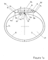
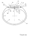
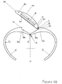
- Each of the bracelets shown in Figures 1 to 4 comprises two rigid arms 10 and 12 curved, a hinge 14 connecting them to each other by one of their ends identified by the letter a , and a head 16, movable and presented in the form of a housing inside which is housed a watch movement 18.
- the two arms 10 and 12 in the closed position, each embrace an angle of about 180 ° together forming a ring with an opening 20 for receiving the wrist of a carrier.
- Their connected ends 10a and 12a are provided with coaxial holes in which a pin AA axis is engaged to achieve a hinge 19 forming the hinge 14.
- These ends further comprise each a flat surface identified by the letter b which are coplanar.
- a protrusion identified by the letter c limits the surfaces 10b and 12b on their opposite side to the hinge 14.
- the head 16 is pivotally mounted at the end 10a of the arm 10, about an axis BB perpendicular to the surface 10b, by means of a tenon head 22 which is integral with it, engaged in a hole made in the end 10a of the arm 10, as can be seen in Figure 1a.
- the tenon 22 thus provides a means of connecting the arm 10 to the head 16.
- the latter comprises a flat lower face 16a, adjacent the surfaces 10b and 12b in the locked position and on which is fixed the pin 22, an upper surface 16b , convex, two lateral faces 16c and two wings 16d intended to cooperate with the protuberances 10c and 12c.
- the protuberances 10c and 12c, with the surfaces 10b and 12b form crampons and the two wings 16d latches each cooperating with one of the crampons, so as to make the head 16 and the arms 10 and 12 integral.
- the crampons and the locks respectively form the first and second parts of the connecting means of the arms 10 and 12 with the head 16.
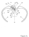
- these connecting means are both triggered when the head 16 is in the position shown in Figure 1b.
- the head 16 In the locked position of the head, shown in Figure 1a, the head 16 is in the general shape of the bracelet, the upper surface 16b extending the arms 10 and 12 and the hinge 19 being covered.
- a force F 1 on one of the side faces 16c substantially perpendicular to the plane of the drawing, and which pivots the head 16 and the pin 22 on the arm 10 , so that the wings 16d are disengaged from the protuberances 10c and 12c.
- the rotation should be about 90 °.
- the head then reaches its unlocked position.
- the force F 3 is perpendicular to F 1 and substantially parallel to the axis BB when it is the surface 12b and the face 16a which form the second connecting means, while it is substantially perpendicular to the axis BB in the another case, which is shown in Figure 1a.
- F 3 has the effect of generating a constraint at the post 22, but without causing a displacement of the head 16 with reference to the arms 10 and 12. The head 16 is thus locked and the arms 10 and 12 remain closed .
- the arms 10 and 12 can be opened only to the extent that the hinge 14 can freely work. This is possible only if the head 16, in the unlocked position, completely releases the surface 12b, and the hinge 19. The arm 12 is thus no longer limited in its movement by the face 16a. This condition is satisfied only if the distance between the axis B-B and the edge 16c is less than the distance between the axes A-A and B-B.
- the arms could also cooperate with a spring, as is done in the marquise watches, so that, during installation, the latter automatically take their closed position.
- the head 16 on the arm 10 removably. This is easily achieved by arranging the pin 22 and the hole in the arm 10 to form a bayonet engagement. In this case, the disengagement will be advantageously after an angle of rotation greater than 90 °, so that the risk of accidental detachment is removed.
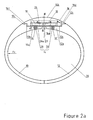
- FIG. 2 differs from that of Figure 1 by the symmetrical structure of the head 16 and its articulation 14.
- the other features are found in a similar manner, identified by the same references.
- the hinge 14 comprises a plate 26 connecting the two ends 10a and 12a and forming with them two hinges 28 and 30 pivoting about axes A-A and
- the plate 26 has a bearing surface 26a which, when the arms are in the closed position as shown in Figure 2a, is in the extension of the surfaces 10b and 12b.
- the surface 26a is of substantially square shape, with a side equal to or greater than the width of the head 16.
- the head 16 is pivotally mounted on the plate 26, about an axis BB perpendicular to the surface 26a and passing through its center, by means of a pin 22, similar in all respects to that used in the embodiment of the invention.
- FIG. 1. The pin 22 thus acts as a connecting means between the head 16 and the plate 26.
- the head 16 is symmetrical, it is possible to rotate it completely on the axis B-B. In this way, by arranging two movements of watches 18 in the head 16, displaying different times, it is possible to select the time displayed by simple rotation of the head.
- the head 16 In the locked position, shown in Figure 2a, the head 16 is in the general shape of the bracelet, the upper surface 16b extending the arms 10 and 12. To separate the head 16 and the arms 10 and 12, it is necessary to apply a force F 1 , substantially perpendicular to the plane of the drawing, on one of the side faces 16c, which pivots the head 16 and the pin 22 on the plate 26, so that the wings 16d separate from the protuberances 10c and 12c. The rotation should be about 90 °. The head then reaches its unlocked position.
- the surfaces 10b and 12b cooperating with the face 16a or the protuberances 10c and 12c with the wings 16d thus form means for connecting the head with the arms 10 and 12.
- the two connecting means of the head and the arms are triggered in the unlocked position, the permanent link function being provided by the pin 22 mounted on the plate 26.
- the arms 10 and 12 can be opened only to the extent that the hinge 14 can freely work. This is possible only if the head 16, in the unlocked position, completely releases the surfaces 10b and 12b, which are no longer limited in their movement by the face 16a. This condition is satisfied only if the distance between the axis BB and the edge 16c is less than the distance between BB and the axes AA and A'-A '.
- the head 16 of the bracelet described with reference to Figure 2 being symmetrical, it can occupy two locking positions, passing from one to the other by a rotation of 180 °. If it is provided with two movements of watches 18 and, as a result of a dual display of the time, it allows the display of two pieces of information, for example the hours of two time zones, the passage from one to the other. other being done by a simple rotation of the head 16.
- the head 16 can be removably mounted on the plate 26 by means of a bayonet assembly.
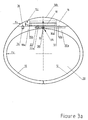
- FIGS. 1 and 2 show a different strap of the two examples described above because the head 16 is slidably mounted on the bearing surfaces 10b and 12b.
- the hinge 14 is identical to that of Figure 1, formed of two coaxial hinges 30, axis A-A, only one being visible in the drawing, separated by a space.
- the same parts bear the same references as in FIGS. 1 and 2.
- the head 16 comprises, as in the two examples described above, a flat lower face 16a, adjacent the surfaces 10b and 12b in the locked position and on which is fixed the pin 22, an upper surface 16b, convex, two side faces 16c .
- the upper surface 16b joins the lower face 16a at each end, so that the head 16 has a section having a cylindrical segment shape, of axis parallel to the axis A-A.
- the surfaces 10b and 12b comprise a groove 32, perpendicular to the axis AA and T-section, serving as a slide.
- the post 22 is provided with a protruding portion 22a, engaged in the groove 32 to form a slider and thus provide a connecting function between the head 16 and the arm 10.
- a spring ball 34 is housed in the arm 10 and protrudes from the surface 10b near its end opposite to the articulation 14.
- a conical hole 36 is formed in the face 16a, arranged so that the ball 34 It houses there when the head 16 is in the locked position.
- the head 16 In the locked position of the head, shown in Figure 3a, the head 16 is in the general shape of the bracelet, the upper surface 16b extending the arms 10 and 12.
- the pin 22 is engaged in the portion of the groove 32 associated the arm 10.
- the head 16 is held in this position by the engagement of the ball 34 in the conical hole 36.
- the arms 10 and 12 can be opened only to the extent that the hinge 14 can freely work. This is only possible if the head 16 completely releases the surface 10b and the hinges 30 in the unlocked position. The arm 10 is then no longer limited in its movement by the face 16a. This condition is satisfied only if the length of the groove 32 is at least equal to the distance between the hinge 14 and the end of the face 16a, the side where the force F 1 is applied.
- the hinge forming the hinge 14 it would also be possible to shift the hinge forming the hinge 14, so that the groove 32 is made only in the arm 12.
- the surface 10b is smaller than the surface 12b.
- the movement of the head 16 to move from one to the other of the locked and unlocked positions is reduced.
- connection means of the arm 12 with the head 16 remain engaged both in the locked and unlatched position of the head 16.
- the head 16 is pivotally mounted on the end 12a of the arm 12, about an axis CC parallel to the AA axis, by means of a hinge 36.
- the latter provides a function of connecting means between the arm 12 and the head 16, which comprises a flat lower face 16a, adjacent the surfaces 10b and 12b in the locked position, a surface upper 16b, curved, two side faces 16c, a first flange 16d intended to cooperate with the protuberance 10c and a second flange 16e arranged to form the hinge 36 with the protrusion 12c.
- the protuberance 10c forms a crampon and the wing 16d a latch, which cooperate with each other so as to make the head 16 and the arms 10 and 12 integral, the wing 16d being engaged notch in the protuberance 10c. and thus providing a function of connecting means between the head 16 and the arm 10.
- This notch can be achieved by a slight overlap of the wing 16d by the protrusion 10c, the arms 10 and 12 being sufficiently elastic to allow the necessary deformation at the release of the head 16. It is also possible to perform this function by means of a spring ball similar to that mentioned with reference to FIG. 3.
- the hinge 36 acts as a connecting means between the arm 12 and the head 16.
- the head 16 In the locked position of the head, shown in Figure 4a, the head 16 is in the general shape of the bracelet, the upper surface 16b extending the arms 10 and 12.
- both the arms 10 and 12 and the head 16 can be considerably changed. It is thus not necessary for the surfaces 10b, 12b and 16a to be flat. They could also be spherical in the first two embodiments, cylindrical in the third and of any shape in the fourth.
- the head could wear a cabochon or a cut stone, rather than being provided with a watch movement. It would also be possible to fix the movement in one of the arms of the bracelet and to be partially masked or not. If the display is hidden, the reading would be done by moving the head 16, but without bringing the latter to its unlocked position, to avoid inadvertent opening of the bracelet.
- the movement 18 could be housed in the arm 12 and the head 16 surround the housing of the movement 18 to form a telescope.
- the two arms 10 and 12 can embrace an angle of less than 180 °.
- the ends 10a and 12a will be arranged to form a stop when the arms are in the closed position.
Landscapes
- Physics & Mathematics (AREA)
- General Physics & Mathematics (AREA)
- Adornments (AREA)
- Buckles (AREA)
- Professional, Industrial, Or Sporting Protective Garments (AREA)
- Pivots And Pivotal Connections (AREA)
- Control And Other Processes For Unpacking Of Materials (AREA)
- Centrifugal Separators (AREA)
- Orthopedics, Nursing, And Contraception (AREA)
Claims (11)
- Ring in der Bauweise, die dazu bestimmt ist, an einem Körperteil eines Trägers angeordnet zu werden, und welcher- zwei starre gekrümmte Arme (10, 12) und ein Gelenk (14), das diese beweglich einander gegenüberliegend am ersten (10a, 12a) ihrer zwei Enden verbindet,- einen Kopf (16), der nahe am Gelenk (14) angeordnet ist und so ausgelegt ist, dass er eine erste Position, die Verriegelungsposition genannt wird, und eine zweite Position einnehmen kann, die Entriegelungsposition genannt wird, und- erste und zweite Verbindungseinrichtungen aufweist, um den Kopf mit dem ersten bzw. dem zweiten Arm fest zu verbinden, wobei die Einrichtungen beide eingehakt werden, wenn sich der Kopf (16) in der Verriegelungsposition befindet und zumindest die ersten dieser Einrichtungen ausgehakt werden, wenn sich der Kopf in der entriegelten Position befindet,wobei der Ring so ausgelegt ist, dass er- eine offene Position einnimmt, in der seine zweiten Enden voneinander beabstandet sind, so dass der Ring durch den Zwischenraum, der sie trennt, an dem Körperteil angebracht oder von ihm abgenommen werden kann, und- eine geschlossene Position einnimmt, bei der der Zwischenraum verringert ist,wobei die Arme den Körperteil umschließen,
dadurch gekennzeichnet,- dass die ersten Verbindungseinrichtungen erste und zweite Teile aufweisen, die starr mit dem ersten Arm bzw. mit dem Kopf verbunden sind. - Ring nach Anspruch 1, dadurch gekennzeichnet, dass das erste und das zweite Teil von einem Riegel (16d) einerseits und einem Haken (10c) andererseits gebildet werden, die dazu bestimmt sind, miteinander zusammenzuwirken, wenn sich der Kopf in der verriegelten Position befindet, und die voneinander gelöst sind, wenn sich der Kopf in der entriegelten Position befindet.
- Ring nach Anspruch 2, dadurch gekennzeichnet, dass die ersten Verbindungseinrichtungen so ausgelegt sind, dass die Verschiebung des Kopfs (16) aus seiner verriegelten Position in seine entriegelte Position durch Anlegen einer ersten Kraft F1 erfolgt und dass eine Kraft F2, die an einen der Arme (10, 12) angelegt wird, wenn sich der Kopf (16) in der verriegelten Position befindet, auf diesen letzteren durch Zusammenwirkung des Riegels (16d) und des Hakens (10c) eine resultierende Kraft F3 erzeugt, die im Wesentlichen senkrecht zur ersten Kraft F1 ist, wobei das Ganze so vor sich geht, dass die Arme (10, 12) in der geschlossenen Position bleiben, solange sich der Kopf in der verriegelten Position befindet, und voneinander getrennt werden können, wenn sich der Kopf (16) in der entriegelten Position befindet.
- Ring nach einem der Ansprüche 1 bis 3, dadurch gekennzeichnet, dass das Gelenk (14) mindestens ein Scharnier (19, 28) aufweist, das mit mindestens einem der Arme fest verbunden ist und das eine erste Schwenkachse (A-A) bildet, wobei das Scharnier verdeckt ist, wenn sich der Kopf (16) in der verriegelten Position befindet, und nicht verdeckt ist, wenn er sich in der entriegelten Position befindet.
- Ring nach Anspruch 4, dadurch gekennzeichnet, dass das Gelenk außerdem ein zweites Scharnier (30), das um eine Achse schwenkt, die parallel zur ersten Achse ist, und ein Plättchen (26) aufweist, das das erste Scharnier (28) mit dem zweiten Scharnier (30) verbindet, wobei das eine (28) der Scharniere mit dem einen Arm (10) und das andere (30) mit dem anderen Arm (12) verbunden ist.
- Ring nach einem der Ansprüche 1 bis 4, dadurch gekennzeichnet, dass der Kopf (16) so ausgelegt ist, dass er durch Verschieben in wenigstens einem (12) der Arme aus der Verriegelungsposition in die Entriegelungsposition und umgekehrt gelangen kann.
- Ring nach Anspruch 6, dadurch gekennzeichnet, dass er außerdem Einrastpositioniereinrichtungen (34) aufweist, die so ausgelegt sind, dass sie einerseits mit dem Kopf (16) und andererseits mit einem der Arme (10) zusammenwirken, um bezogen auf die Arme die verriegelte Position des Kopfes zu gewährleisten.
- Ring nach einem der Ansprüche 4 und 5, dadurch gekennzeichnet, dass der Kopf so ausgelegt ist, dass er durch Drehen um eine zur ersten Achse (A-A) senkrechte zweite Achse (B-B) von der Verriegelungsposition in die Entriegelungsposition und umgekehrt gelangt.
- Ring nach Anspruch 8, dadurch gekennzeichnet, dass mindestens einer der Arme (10) einen Vorsprung (10c) und der Kopf (16) einen Flügel (16d) aufweist, wobei von dem Vorsprung und dem Flügel der eine den Riegel und der andere den Haken bildet.
- Ring nach einem der Ansprüche 2 und 3, dadurch gekennzeichnet, dass der Kopf (16) mit dem einen seiner Enden auf einem der Arme (12) um eine dritte Achse (C-C) schwenkbar angebracht ist, die parallel zur ersten Achse (A-A) ist, und über das andere Ende mit dem anderen Arm (10) zusammenwirkt, um eine Rastverbindung zu bilden.
- Ring nach einem der Ansprüche 1 bis 10, dadurch gekennzeichnet, dass die Verbindungseinrichtungen so ausgelegt sind, dass der Kopf (16) zwei Verriegelungspositionen einnehmen kann und mit einer Uhrvorrichtung (18) versehen ist, die zwei verschiedene Anzeigen aufweist, die in der ersten bzw. in der zweiten Verriegelungsposition sichtbar sind.
Priority Applications (1)
| Application Number | Priority Date | Filing Date | Title |
|---|---|---|---|
| EP02743505A EP1404190B1 (de) | 2001-07-11 | 2002-07-10 | Schwenkbarer offener ring |
Applications Claiming Priority (4)
| Application Number | Priority Date | Filing Date | Title |
|---|---|---|---|
| EP01116879A EP1275319A1 (de) | 2001-07-11 | 2001-07-11 | Schwenkbarer offener Ring |
| EP01116879 | 2001-07-11 | ||
| EP02743505A EP1404190B1 (de) | 2001-07-11 | 2002-07-10 | Schwenkbarer offener ring |
| PCT/IB2002/002706 WO2003005850A1 (fr) | 2001-07-11 | 2002-07-10 | Anneau ouvert articule |
Publications (2)
| Publication Number | Publication Date |
|---|---|
| EP1404190A1 EP1404190A1 (de) | 2004-04-07 |
| EP1404190B1 true EP1404190B1 (de) | 2006-10-11 |
Family
ID=8178015
Family Applications (2)
| Application Number | Title | Priority Date | Filing Date |
|---|---|---|---|
| EP01116879A Withdrawn EP1275319A1 (de) | 2001-07-11 | 2001-07-11 | Schwenkbarer offener Ring |
| EP02743505A Expired - Lifetime EP1404190B1 (de) | 2001-07-11 | 2002-07-10 | Schwenkbarer offener ring |
Family Applications Before (1)
| Application Number | Title | Priority Date | Filing Date |
|---|---|---|---|
| EP01116879A Withdrawn EP1275319A1 (de) | 2001-07-11 | 2001-07-11 | Schwenkbarer offener Ring |
Country Status (9)
| Country | Link |
|---|---|
| US (1) | US7017368B2 (de) |
| EP (2) | EP1275319A1 (de) |
| JP (1) | JP2004533897A (de) |
| KR (1) | KR20040038978A (de) |
| CN (1) | CN1236713C (de) |
| AT (1) | ATE341959T1 (de) |
| DE (1) | DE60215349D1 (de) |
| TW (1) | TW582995B (de) |
| WO (1) | WO2003005850A1 (de) |
Families Citing this family (15)
| Publication number | Priority date | Publication date | Assignee | Title |
|---|---|---|---|---|
| KR20070111012A (ko) * | 2006-05-16 | 2007-11-21 | 삼성전자주식회사 | 와치 타입 휴대 단말기 |
| US7799979B2 (en) * | 2008-11-20 | 2010-09-21 | Swartz Patrick Neil | Plectrum mounting apparatus and method of use |
| USD622128S1 (en) | 2009-09-25 | 2010-08-24 | MCL Design, Inc. | Hinge |
| EP2579107B1 (de) * | 2011-10-05 | 2020-09-02 | Suunto Oy | Uhrengehäuse und Armbanduhrvorrichtung |
| US20140102136A1 (en) * | 2012-10-12 | 2014-04-17 | Michael K. Warren | Jewelry piece with interchangeable rfid tag |
| EP2967202A4 (de) | 2013-03-15 | 2016-11-23 | Himanshu Singh | Ringschutzvorrichtung |
| KR20160080821A (ko) * | 2014-12-26 | 2016-07-08 | 쓰리엠 이노베이티브 프로퍼티즈 캄파니 | 스트랩 길이를 조절하는 버클 및 이를 포함하는 호흡 마스크 |
| CN106963352A (zh) * | 2017-04-24 | 2017-07-21 | 苏州国科智策智能科技有限公司 | 压力可控的合体式智能健康指环 |
| US11284685B2 (en) | 2017-08-09 | 2022-03-29 | Guaicaipuro Rodriguez Garcia | Openable finger ring system |
| KR102082209B1 (ko) * | 2018-05-24 | 2020-02-27 | 이연서 | 셀룰로오스 아세테이트 재활용 블록을 이용한 팔찌 |
| US20200121038A1 (en) | 2018-10-23 | 2020-04-23 | Cecil James Pounder, III | Jewelry |
| USD909230S1 (en) | 2018-10-23 | 2021-02-02 | Cecil James Pounder, III | Article of jewelry |
| US11087724B1 (en) * | 2018-11-08 | 2021-08-10 | Cole Eshee Heve McBride | Spring loaded thumb pick |
| US11800911B2 (en) | 2021-04-12 | 2023-10-31 | Steve Govea Suarez | Radial watch |
| CN113349528B (zh) * | 2021-07-01 | 2022-12-02 | 深圳市纳晶云科技有限公司 | 一种可单手佩戴使用的智能手表 |
Family Cites Families (19)
| Publication number | Priority date | Publication date | Assignee | Title |
|---|---|---|---|---|
| US1128084A (en) * | 1913-05-27 | 1915-02-09 | Charles S Wilcoxon | Ring. |
| FR940506A (fr) * | 1947-01-23 | 1948-12-15 | Bracelet | |
| US3182876A (en) * | 1963-12-23 | 1965-05-11 | Ibm | Bursting device for multilayer webs |
| US3465543A (en) * | 1966-03-08 | 1969-09-09 | John T Baker | Openable finger ring with pivoted locking element |
| US3566616A (en) * | 1969-02-14 | 1971-03-02 | Robert A Benedict Jr | Ornamental finger ring having a separable connection in its band |
| US3736770A (en) * | 1971-02-26 | 1973-06-05 | J Kelrick | Adjustable ring having bridge element and firmly secured notched latch bar |
| US4236384A (en) * | 1978-09-01 | 1980-12-02 | Daub Arthur R | Locking assembly for article of jewelry |
| US4753087A (en) * | 1985-11-12 | 1988-06-28 | Annunzio Philip D | Adjustable ring structure |
| EP0313710B1 (de) * | 1987-10-26 | 1992-06-17 | Premiere De Tabbah Sa | Schmuckstück |
| US4790148A (en) * | 1987-12-10 | 1988-12-13 | Gerard Faini | Ring shank |
| US4879883A (en) * | 1988-08-09 | 1989-11-14 | Bruner Mates A | Openable ring with unique locking and release means |
| GB8830050D0 (en) * | 1988-12-23 | 1989-02-22 | Creates Allan | Finger ring |
| US5136858A (en) * | 1991-05-03 | 1992-08-11 | Bruner Mates A | Openable ring with interleaving member |
| US5651273A (en) * | 1993-06-29 | 1997-07-29 | Davida Enterprises, Inc. | Hinged finger ring |
| US5816073A (en) * | 1997-02-11 | 1998-10-06 | Marquesa, Inc. | Hinged earring |
| US6085550A (en) * | 1998-02-09 | 2000-07-11 | Ishida; Mitsugi | Adjustable article of jewelry and related method |
| DK175003B1 (da) * | 1999-04-28 | 2004-04-19 | Daniel Bentley | Fingerring |
| US20020069670A1 (en) * | 2000-12-11 | 2002-06-13 | Edward Rosenberg | System for sizing and re-sizing articles of jewelry |
| US6568214B2 (en) * | 2001-03-16 | 2003-05-27 | Michael Wolff | Hinged ring that supports an ornament and a system and method for making same |
-
2001
- 2001-07-11 EP EP01116879A patent/EP1275319A1/de not_active Withdrawn
-
2002
- 2002-07-10 JP JP2003511664A patent/JP2004533897A/ja not_active Abandoned
- 2002-07-10 DE DE60215349T patent/DE60215349D1/de not_active Expired - Lifetime
- 2002-07-10 KR KR10-2004-7000342A patent/KR20040038978A/ko not_active Withdrawn
- 2002-07-10 WO PCT/IB2002/002706 patent/WO2003005850A1/fr not_active Ceased
- 2002-07-10 EP EP02743505A patent/EP1404190B1/de not_active Expired - Lifetime
- 2002-07-10 AT AT02743505T patent/ATE341959T1/de not_active IP Right Cessation
- 2002-07-10 CN CNB028130820A patent/CN1236713C/zh not_active Expired - Fee Related
- 2002-07-10 US US10/480,711 patent/US7017368B2/en not_active Expired - Fee Related
- 2002-10-25 TW TW091125014A patent/TW582995B/zh not_active IP Right Cessation
Also Published As
| Publication number | Publication date |
|---|---|
| EP1275319A1 (de) | 2003-01-15 |
| DE60215349D1 (de) | 2006-11-23 |
| JP2004533897A (ja) | 2004-11-11 |
| KR20040038978A (ko) | 2004-05-08 |
| US20040172968A1 (en) | 2004-09-09 |
| ATE341959T1 (de) | 2006-11-15 |
| CN1522117A (zh) | 2004-08-18 |
| EP1404190A1 (de) | 2004-04-07 |
| WO2003005850A1 (fr) | 2003-01-23 |
| TW582995B (en) | 2004-04-11 |
| US7017368B2 (en) | 2006-03-28 |
| CN1236713C (zh) | 2006-01-18 |
Similar Documents
| Publication | Publication Date | Title |
|---|---|---|
| EP1404190A1 (de) | Schwenkbarer offener ring | |
| EP3414630B1 (de) | Umdrehbares uhrenarmband mit multiplen konfigurationen | |
| WO2009030984A1 (fr) | Montre-bracelet comportant un dispositif de réversibilité | |
| EP0865742B1 (de) | Faltverschluss für Armbänder | |
| EP3928652B1 (de) | Verschlussvorrichtung für armbandverschluss | |
| CH715870B1 (fr) | Système de fixation pour bracelets. | |
| EP2120625B1 (de) | Uhrarmband | |
| EP3206092A1 (de) | Umdrehbares uhrenarmband mit multiplen konfigurationen | |
| CH716020A2 (fr) | Pièce d'horlogerie comprenant une lunette avec une fixation élastique. | |
| WO2018083388A1 (fr) | Bijou | |
| CH716815B1 (fr) | Article de bijouterie comprenant un fermoir. | |
| WO2023078836A1 (fr) | Assemblage d'un brin de bracelet sur une boîte de montre | |
| EP1971236B1 (de) | Ausziehbare vorrichtung für uhrenarmband | |
| FR2743641A1 (fr) | Montre-bracelet a cornes munie d'un dispositif de fixation d'un bracelet aux cornes et bracelet pour une telle montre | |
| WO2010108297A1 (fr) | Article d'ornement | |
| WO2025210450A1 (fr) | Bracelet rigide notamment pour pièce d'horlogerie | |
| CH709653B1 (fr) | Ensemble articulé et monture de lunettes comportant un tel ensemble. | |
| CH712115A2 (fr) | Montre-bracelet dont le bracelet peut être retiré sans outil. | |
| WO1982004335A1 (fr) | Montre munie d'un organe de liaison | |
| EP4544951A1 (de) | Verschluss für armband | |
| CH713974A2 (fr) | Dispositif de liaison mécanique pour composants d'habillage horloger, notamment en forme de barrette de fixation. | |
| FR3163535A1 (fr) | Boucle de ceinture, notamment de maroquinerie, et ceinture, notamment de maroquinerie, comportant une telle boucle | |
| WO2025027488A1 (fr) | Boîte de montre | |
| EP4541222A1 (de) | Faltverschluss für armband, insbesondere für armbanduhren | |
| CH690519A5 (fr) | Montre-bracelet à cornes munie d'un dispositif de fixation d'un bracelet aux cornes et bracelet notamment pour une telle montre. |
Legal Events
| Date | Code | Title | Description |
|---|---|---|---|
| PUAI | Public reference made under article 153(3) epc to a published international application that has entered the european phase |
Free format text: ORIGINAL CODE: 0009012 |
|
| 17P | Request for examination filed |
Effective date: 20031212 |
|
| AK | Designated contracting states |
Kind code of ref document: A1 Designated state(s): AT BE BG CH CY CZ DE DK EE ES FI FR GB GR IE IT LI LU MC NL PT |
|
| AX | Request for extension of the european patent |
Extension state: AL LT LV MK RO SI |
|
| RBV | Designated contracting states (corrected) |
Designated state(s): AT BE BG CH CY CZ DE DK EE ES FI FR GB GR IE IT LI LU MC NL PT SE SK TR |
|
| RIN1 | Information on inventor provided before grant (corrected) |
Inventor name: HUG, DOMINIQUE, MARCO |
|
| GRAP | Despatch of communication of intention to grant a patent |
Free format text: ORIGINAL CODE: EPIDOSNIGR1 |
|
| GRAS | Grant fee paid |
Free format text: ORIGINAL CODE: EPIDOSNIGR3 |
|
| GRAA | (expected) grant |
Free format text: ORIGINAL CODE: 0009210 |
|
| RIN1 | Information on inventor provided before grant (corrected) |
Inventor name: HUG, DOMINIQUE, MARCO |
|
| AK | Designated contracting states |
Kind code of ref document: B1 Designated state(s): AT BE BG CH CY CZ DE DK EE ES FI FR GB GR IE IT LI LU MC NL PT SE SK TR |
|
| PG25 | Lapsed in a contracting state [announced via postgrant information from national office to epo] |
Ref country code: IT Free format text: LAPSE BECAUSE OF FAILURE TO SUBMIT A TRANSLATION OF THE DESCRIPTION OR TO PAY THE FEE WITHIN THE PRESCRIBED TIME-LIMIT;WARNING: LAPSES OF ITALIAN PATENTS WITH EFFECTIVE DATE BEFORE 2007 MAY HAVE OCCURRED AT ANY TIME BEFORE 2007. THE CORRECT EFFECTIVE DATE MAY BE DIFFERENT FROM THE ONE RECORDED. Effective date: 20061011 Ref country code: CZ Free format text: LAPSE BECAUSE OF FAILURE TO SUBMIT A TRANSLATION OF THE DESCRIPTION OR TO PAY THE FEE WITHIN THE PRESCRIBED TIME-LIMIT Effective date: 20061011 Ref country code: SK Free format text: LAPSE BECAUSE OF FAILURE TO SUBMIT A TRANSLATION OF THE DESCRIPTION OR TO PAY THE FEE WITHIN THE PRESCRIBED TIME-LIMIT Effective date: 20061011 Ref country code: IE Free format text: LAPSE BECAUSE OF FAILURE TO SUBMIT A TRANSLATION OF THE DESCRIPTION OR TO PAY THE FEE WITHIN THE PRESCRIBED TIME-LIMIT Effective date: 20061011 Ref country code: FI Free format text: LAPSE BECAUSE OF FAILURE TO SUBMIT A TRANSLATION OF THE DESCRIPTION OR TO PAY THE FEE WITHIN THE PRESCRIBED TIME-LIMIT Effective date: 20061011 Ref country code: AT Free format text: LAPSE BECAUSE OF FAILURE TO SUBMIT A TRANSLATION OF THE DESCRIPTION OR TO PAY THE FEE WITHIN THE PRESCRIBED TIME-LIMIT Effective date: 20061011 Ref country code: NL Free format text: LAPSE BECAUSE OF FAILURE TO SUBMIT A TRANSLATION OF THE DESCRIPTION OR TO PAY THE FEE WITHIN THE PRESCRIBED TIME-LIMIT Effective date: 20061011 |
|
| REG | Reference to a national code |
Ref country code: GB Ref legal event code: FG4D Free format text: NOT ENGLISH |
|
| REG | Reference to a national code |
Ref country code: CH Ref legal event code: EP |
|
| REG | Reference to a national code |
Ref country code: IE Ref legal event code: FG4D Free format text: LANGUAGE OF EP DOCUMENT: FRENCH |
|
| REF | Corresponds to: |
Ref document number: 60215349 Country of ref document: DE Date of ref document: 20061123 Kind code of ref document: P |
|
| REG | Reference to a national code |
Ref country code: CH Ref legal event code: NV Representative=s name: INFOSUISSE INFORMATION HORLOGERE ET INDUSTRIELLE |
|
| PG25 | Lapsed in a contracting state [announced via postgrant information from national office to epo] |
Ref country code: BG Free format text: LAPSE BECAUSE OF FAILURE TO SUBMIT A TRANSLATION OF THE DESCRIPTION OR TO PAY THE FEE WITHIN THE PRESCRIBED TIME-LIMIT Effective date: 20070111 Ref country code: DK Free format text: LAPSE BECAUSE OF FAILURE TO SUBMIT A TRANSLATION OF THE DESCRIPTION OR TO PAY THE FEE WITHIN THE PRESCRIBED TIME-LIMIT Effective date: 20070111 Ref country code: SE Free format text: LAPSE BECAUSE OF FAILURE TO SUBMIT A TRANSLATION OF THE DESCRIPTION OR TO PAY THE FEE WITHIN THE PRESCRIBED TIME-LIMIT Effective date: 20070111 |
|
| PG25 | Lapsed in a contracting state [announced via postgrant information from national office to epo] |
Ref country code: DE Free format text: LAPSE BECAUSE OF FAILURE TO SUBMIT A TRANSLATION OF THE DESCRIPTION OR TO PAY THE FEE WITHIN THE PRESCRIBED TIME-LIMIT Effective date: 20070112 |
|
| PG25 | Lapsed in a contracting state [announced via postgrant information from national office to epo] |
Ref country code: ES Free format text: LAPSE BECAUSE OF FAILURE TO SUBMIT A TRANSLATION OF THE DESCRIPTION OR TO PAY THE FEE WITHIN THE PRESCRIBED TIME-LIMIT Effective date: 20070122 |
|
| PG25 | Lapsed in a contracting state [announced via postgrant information from national office to epo] |
Ref country code: PT Free format text: LAPSE BECAUSE OF FAILURE TO SUBMIT A TRANSLATION OF THE DESCRIPTION OR TO PAY THE FEE WITHIN THE PRESCRIBED TIME-LIMIT Effective date: 20070319 |
|
| NLV1 | Nl: lapsed or annulled due to failure to fulfill the requirements of art. 29p and 29m of the patents act | ||
| GBV | Gb: ep patent (uk) treated as always having been void in accordance with gb section 77(7)/1977 [no translation filed] |
Effective date: 20061011 |
|
| REG | Reference to a national code |
Ref country code: IE Ref legal event code: FD4D |
|
| PLBE | No opposition filed within time limit |
Free format text: ORIGINAL CODE: 0009261 |
|
| STAA | Information on the status of an ep patent application or granted ep patent |
Free format text: STATUS: NO OPPOSITION FILED WITHIN TIME LIMIT |
|
| 26N | No opposition filed |
Effective date: 20070712 |
|
| PG25 | Lapsed in a contracting state [announced via postgrant information from national office to epo] |
Ref country code: GB Free format text: LAPSE BECAUSE OF FAILURE TO SUBMIT A TRANSLATION OF THE DESCRIPTION OR TO PAY THE FEE WITHIN THE PRESCRIBED TIME-LIMIT Effective date: 20061011 |
|
| REG | Reference to a national code |
Ref country code: CH Ref legal event code: PFA Owner name: AJS PRODUCTION SA Free format text: AJS PRODUCTION SA#RUE DU GENERAL-COMMAN 25#2950 COURGENAY (CH) $ HARTCASE CORPORATION#2500 WESTCHESTER AVENUE, SUITE 103#PURCHASE, NY 10577 (US) -TRANSFER TO- AJS PRODUCTION SA#RUE DU GENERAL-COMMAN 25#2950 COURGENAY (CH) $ HARTCASE CORPORATION#84 BUSINESS PARK DRIVE SUITE 208#ARMONK, NY 10504 (US) |
|
| BERE | Be: lapsed |
Owner name: AJS PRODUCTION SA Effective date: 20070731 Owner name: HARTCASE CORP. Effective date: 20070731 |
|
| PG25 | Lapsed in a contracting state [announced via postgrant information from national office to epo] |
Ref country code: MC Free format text: LAPSE BECAUSE OF NON-PAYMENT OF DUE FEES Effective date: 20070731 Ref country code: GR Free format text: LAPSE BECAUSE OF FAILURE TO SUBMIT A TRANSLATION OF THE DESCRIPTION OR TO PAY THE FEE WITHIN THE PRESCRIBED TIME-LIMIT Effective date: 20070112 |
|
| REG | Reference to a national code |
Ref country code: FR Ref legal event code: ST Effective date: 20080331 |
|
| PG25 | Lapsed in a contracting state [announced via postgrant information from national office to epo] |
Ref country code: BE Free format text: LAPSE BECAUSE OF NON-PAYMENT OF DUE FEES Effective date: 20070731 |
|
| PG25 | Lapsed in a contracting state [announced via postgrant information from national office to epo] |
Ref country code: FR Free format text: LAPSE BECAUSE OF NON-PAYMENT OF DUE FEES Effective date: 20070731 |
|
| PG25 | Lapsed in a contracting state [announced via postgrant information from national office to epo] |
Ref country code: EE Free format text: LAPSE BECAUSE OF FAILURE TO SUBMIT A TRANSLATION OF THE DESCRIPTION OR TO PAY THE FEE WITHIN THE PRESCRIBED TIME-LIMIT Effective date: 20061011 |
|
| PG25 | Lapsed in a contracting state [announced via postgrant information from national office to epo] |
Ref country code: CY Free format text: LAPSE BECAUSE OF FAILURE TO SUBMIT A TRANSLATION OF THE DESCRIPTION OR TO PAY THE FEE WITHIN THE PRESCRIBED TIME-LIMIT Effective date: 20061011 Ref country code: LU Free format text: LAPSE BECAUSE OF NON-PAYMENT OF DUE FEES Effective date: 20070710 |
|
| PG25 | Lapsed in a contracting state [announced via postgrant information from national office to epo] |
Ref country code: TR Free format text: LAPSE BECAUSE OF FAILURE TO SUBMIT A TRANSLATION OF THE DESCRIPTION OR TO PAY THE FEE WITHIN THE PRESCRIBED TIME-LIMIT Effective date: 20061011 |
|
| REG | Reference to a national code |
Ref country code: CH Ref legal event code: NV Representative=s name: GLN S.A. |
|
| REG | Reference to a national code |
Ref country code: CH Ref legal event code: PUE Owner name: AJS PRODUCTION SA Free format text: AJS PRODUCTION SA#RUE DU GENERAL-COMMAN 25#2950 COURGENAY (CH) $ HARTCASE CORPORATION#84 BUSINESS PARK DRIVE SUITE 208#ARMONK, NY 10504 (US) -TRANSFER TO- AJS PRODUCTION SA#RUE DU GENERAL-COMMAN 25#2950 COURGENAY (CH) $ PAUL HARTZBAND#ONE BECKENRIDGE ROAD CHAPPAQUA,#NEW YORK, NY 10514 (US) |
|
| REG | Reference to a national code |
Ref country code: CH Ref legal event code: PCOW Free format text: AJS PRODUCTION SA;RUE DU GENERAL-COMMAN 25;2950 COURGENAY (CH) $ PAUL HARTZBAND;ONE BRECKENRIDGE ROAD;CHAPPAQUA, NEW YORK 10514 (US) |
|
| REG | Reference to a national code |
Ref country code: CH Ref legal event code: PK |
|
| REG | Reference to a national code |
Ref country code: CH Ref legal event code: PCAR Free format text: NEW ADDRESS: AVENUE EDOUARD-DUBOIS 20, 2000 NEUCHATEL (CH) |
|
| PGFP | Annual fee paid to national office [announced via postgrant information from national office to epo] |
Ref country code: CH Payment date: 20130729 Year of fee payment: 12 |
|
| REG | Reference to a national code |
Ref country code: CH Ref legal event code: PL |
|
| PG25 | Lapsed in a contracting state [announced via postgrant information from national office to epo] |
Ref country code: LI Free format text: LAPSE BECAUSE OF NON-PAYMENT OF DUE FEES Effective date: 20140731 Ref country code: CH Free format text: LAPSE BECAUSE OF NON-PAYMENT OF DUE FEES Effective date: 20140731 |