EP1404202B1 - Verfahren, system und vorrichtung zur zubereitung einer getränkeportion, z.b. von kaffee - Google Patents
Verfahren, system und vorrichtung zur zubereitung einer getränkeportion, z.b. von kaffee Download PDFInfo
- Publication number
- EP1404202B1 EP1404202B1 EP02736287A EP02736287A EP1404202B1 EP 1404202 B1 EP1404202 B1 EP 1404202B1 EP 02736287 A EP02736287 A EP 02736287A EP 02736287 A EP02736287 A EP 02736287A EP 1404202 B1 EP1404202 B1 EP 1404202B1
- Authority
- EP
- European Patent Office
- Prior art keywords
- outlet
- inlet
- extreme position
- way valve
- liquid flow
- Prior art date
- Legal status (The legal status is an assumption and is not a legal conclusion. Google has not performed a legal analysis and makes no representation as to the accuracy of the status listed.)
- Expired - Lifetime
Links
- 235000013361 beverage Nutrition 0.000 title claims abstract description 41
- 235000013353 coffee beverage Nutrition 0.000 title claims description 7
- 239000007788 liquid Substances 0.000 claims abstract description 61
- XLYOFNOQVPJJNP-UHFFFAOYSA-N water Substances O XLYOFNOQVPJJNP-UHFFFAOYSA-N 0.000 claims description 43
- 239000012530 fluid Substances 0.000 claims description 41
- 238000005086 pumping Methods 0.000 claims description 3
- 235000009470 Theobroma cacao Nutrition 0.000 claims description 2
- 244000240602 cacao Species 0.000 claims 1
- 230000007423 decrease Effects 0.000 description 9
- 238000007789 sealing Methods 0.000 description 5
- 230000000903 blocking effect Effects 0.000 description 3
- 244000269722 Thea sinensis Species 0.000 description 2
- 244000299461 Theobroma cacao Species 0.000 description 1
- 230000009286 beneficial effect Effects 0.000 description 1
- 235000020140 chocolate milk drink Nutrition 0.000 description 1
- 235000020152 coffee milk drink Nutrition 0.000 description 1
- 235000020965 cold beverage Nutrition 0.000 description 1
- 239000008236 heating water Substances 0.000 description 1
- 230000000717 retained effect Effects 0.000 description 1
Images


Classifications
-
- A—HUMAN NECESSITIES
- A47—FURNITURE; DOMESTIC ARTICLES OR APPLIANCES; COFFEE MILLS; SPICE MILLS; SUCTION CLEANERS IN GENERAL
- A47J—KITCHEN EQUIPMENT; COFFEE MILLS; SPICE MILLS; APPARATUS FOR MAKING BEVERAGES
- A47J31/00—Apparatus for making beverages
- A47J31/24—Coffee-making apparatus in which hot water is passed through the filter under pressure, i.e. in which the coffee grounds are extracted under pressure
- A47J31/34—Coffee-making apparatus in which hot water is passed through the filter under pressure, i.e. in which the coffee grounds are extracted under pressure with hot water under liquid pressure
- A47J31/36—Coffee-making apparatus in which hot water is passed through the filter under pressure, i.e. in which the coffee grounds are extracted under pressure with hot water under liquid pressure with mechanical pressure-producing means
-
- A—HUMAN NECESSITIES
- A47—FURNITURE; DOMESTIC ARTICLES OR APPLIANCES; COFFEE MILLS; SPICE MILLS; SUCTION CLEANERS IN GENERAL
- A47J—KITCHEN EQUIPMENT; COFFEE MILLS; SPICE MILLS; APPARATUS FOR MAKING BEVERAGES
- A47J31/00—Apparatus for making beverages
- A47J31/44—Parts or details or accessories of beverage-making apparatus
- A47J31/46—Dispensing spouts, pumps, drain valves or like liquid transporting devices
- A47J31/461—Valves, e.g. drain valves
-
- A—HUMAN NECESSITIES
- A47—FURNITURE; DOMESTIC ARTICLES OR APPLIANCES; COFFEE MILLS; SPICE MILLS; SUCTION CLEANERS IN GENERAL
- A47J—KITCHEN EQUIPMENT; COFFEE MILLS; SPICE MILLS; APPARATUS FOR MAKING BEVERAGES
- A47J31/00—Apparatus for making beverages
- A47J31/44—Parts or details or accessories of beverage-making apparatus
- A47J31/54—Water boiling vessels in beverage making machines
-
- F—MECHANICAL ENGINEERING; LIGHTING; HEATING; WEAPONS; BLASTING
- F16—ENGINEERING ELEMENTS AND UNITS; GENERAL MEASURES FOR PRODUCING AND MAINTAINING EFFECTIVE FUNCTIONING OF MACHINES OR INSTALLATIONS; THERMAL INSULATION IN GENERAL
- F16K—VALVES; TAPS; COCKS; ACTUATING-FLOATS; DEVICES FOR VENTING OR AERATING
- F16K11/00—Multiple-way valves, e.g. mixing valves; Pipe fittings incorporating such valves
- F16K11/10—Multiple-way valves, e.g. mixing valves; Pipe fittings incorporating such valves with two or more closure members not moving as a unit
- F16K11/105—Three-way check or safety valves with two or more closure members
-
- F—MECHANICAL ENGINEERING; LIGHTING; HEATING; WEAPONS; BLASTING
- F16—ENGINEERING ELEMENTS AND UNITS; GENERAL MEASURES FOR PRODUCING AND MAINTAINING EFFECTIVE FUNCTIONING OF MACHINES OR INSTALLATIONS; THERMAL INSULATION IN GENERAL
- F16K—VALVES; TAPS; COCKS; ACTUATING-FLOATS; DEVICES FOR VENTING OR AERATING
- F16K15/00—Check valves
- F16K15/14—Check valves with flexible valve members
- F16K15/1402—Check valves with flexible valve members having an integral flexible member cooperating with a plurality of seating surfaces
-
- F—MECHANICAL ENGINEERING; LIGHTING; HEATING; WEAPONS; BLASTING
- F16—ENGINEERING ELEMENTS AND UNITS; GENERAL MEASURES FOR PRODUCING AND MAINTAINING EFFECTIVE FUNCTIONING OF MACHINES OR INSTALLATIONS; THERMAL INSULATION IN GENERAL
- F16K—VALVES; TAPS; COCKS; ACTUATING-FLOATS; DEVICES FOR VENTING OR AERATING
- F16K15/00—Check valves
- F16K15/14—Check valves with flexible valve members
- F16K15/148—Check valves with flexible valve members the closure elements being fixed in their centre
-
- F—MECHANICAL ENGINEERING; LIGHTING; HEATING; WEAPONS; BLASTING
- F16—ENGINEERING ELEMENTS AND UNITS; GENERAL MEASURES FOR PRODUCING AND MAINTAINING EFFECTIVE FUNCTIONING OF MACHINES OR INSTALLATIONS; THERMAL INSULATION IN GENERAL
- F16K—VALVES; TAPS; COCKS; ACTUATING-FLOATS; DEVICES FOR VENTING OR AERATING
- F16K23/00—Valves for preventing drip from nozzles
-
- Y—GENERAL TAGGING OF NEW TECHNOLOGICAL DEVELOPMENTS; GENERAL TAGGING OF CROSS-SECTIONAL TECHNOLOGIES SPANNING OVER SEVERAL SECTIONS OF THE IPC; TECHNICAL SUBJECTS COVERED BY FORMER USPC CROSS-REFERENCE ART COLLECTIONS [XRACs] AND DIGESTS
- Y10—TECHNICAL SUBJECTS COVERED BY FORMER USPC
- Y10T—TECHNICAL SUBJECTS COVERED BY FORMER US CLASSIFICATION
- Y10T137/00—Fluid handling
- Y10T137/7722—Line condition change responsive valves
- Y10T137/7781—With separate connected fluid reactor surface
- Y10T137/7784—Responsive to change in rate of fluid flow
- Y10T137/7787—Expansible chamber subject to differential pressures
- Y10T137/7788—Pressures across fixed choke
-
- Y—GENERAL TAGGING OF NEW TECHNOLOGICAL DEVELOPMENTS; GENERAL TAGGING OF CROSS-SECTIONAL TECHNOLOGIES SPANNING OVER SEVERAL SECTIONS OF THE IPC; TECHNICAL SUBJECTS COVERED BY FORMER USPC CROSS-REFERENCE ART COLLECTIONS [XRACs] AND DIGESTS
- Y10—TECHNICAL SUBJECTS COVERED BY FORMER USPC
- Y10T—TECHNICAL SUBJECTS COVERED BY FORMER US CLASSIFICATION
- Y10T137/00—Fluid handling
- Y10T137/7722—Line condition change responsive valves
- Y10T137/7837—Direct response valves [i.e., check valve type]
- Y10T137/7838—Plural
- Y10T137/7842—Diverse types
-
- Y—GENERAL TAGGING OF NEW TECHNOLOGICAL DEVELOPMENTS; GENERAL TAGGING OF CROSS-SECTIONAL TECHNOLOGIES SPANNING OVER SEVERAL SECTIONS OF THE IPC; TECHNICAL SUBJECTS COVERED BY FORMER USPC CROSS-REFERENCE ART COLLECTIONS [XRACs] AND DIGESTS
- Y10—TECHNICAL SUBJECTS COVERED BY FORMER USPC
- Y10T—TECHNICAL SUBJECTS COVERED BY FORMER US CLASSIFICATION
- Y10T137/00—Fluid handling
- Y10T137/7722—Line condition change responsive valves
- Y10T137/7837—Direct response valves [i.e., check valve type]
- Y10T137/7879—Resilient material valve
Definitions
- the invention relates to an apparatus for preparing at least one type of beverage suitable for consumption such as coffee or chocolate milk on the basis of a hot liquid such as water, provided with a storage tank which, in use, is filled with a liquid such as water, a heater and a three-way valve, wherein the three-way valve is provided with an inlet, a first outlet and a second outlet, wherein a pump is in fluid communication with the storage tank and an inlet of the heater for pumping the liquid from the storage tank to the boiler and wherein an outlet of the heater is in fluid communication with the inlet of the three-way valve, the first outlet of the three-way valve being in fluid communication via a first outflow path with the storage tank and/or an inlet of the pump for returning liquid from the three-way valve to the storage tank and/or the pump, and wherein the second outlet of the three-way valve is in fluid communication via a second outflow path with a beverage preparing unit for preparing a beverage suitable for consumption on the basis of the hot liquid, wherein the three-way valve
- Such an apparatus and three-way valve are known per se.
- the known three-way valve is provided with a compartment comprising the inlet, the first outlet and the second outlet.
- the first member is of convex design.
- a check valve is included in the second outflow path.
- the operation of the known apparatus is as follows.
- the storage tank is filled with water.
- the pump is started. It pumps water from the storage tank to the heater.
- the water is heated by the heater.
- the water is pumped further via the heater to the inlet of the three-way valve.
- the first member Under the influence of a water flow from the inlet to the first and/or second outlet, the first member will move towards the first outlet and rapidly close off the first outlet.
- the first outlet then remains closed off due to the pressure prevailing in the three-way valve. Consequently, the water which is pumped via the inlet into the three-way valve will only be able to leave the three-way valve via the second outlet, and flows further via the second outflow path to the beverage preparing unit known per se.
- Such a beverage preparing unit known per se is for instance described in Dutch patent application 1006034 (or European patent application EP 0 878 158).
- a café crème is formed which is dispensed into a small mug or a cup.
- the pump is stopped.
- the heater will continue dispensing expansion water for some time because the heater has not cooled down yet.
- This expansion water will flow to the beverage preparing unit and cause it to drip.
- the check valve has a high flow resistance so that the pressure in the three-way valve, after the pump has been stopped, will decrease relatively slowly. As a result, the member will move relatively slowly from the first outlet to the inlet. Accordingly, it takes relatively long before the first outlet is opened again. After the first outlet has opened, the expansion water can be returned from the heater via the first outlet to the storage tank and/or the inlet of the pump.
- a disadvantage of the known apparatus is that after the pump has been deactivated, it takes relatively long before the member clears the first outlet. This results particularly in the expansion water being supplied via the second outflow path to the beverage preparing unit while the pump has already stopped. This causes dripping and a spread in the brewing time, and hence an undesired spread in the quality of the beverage. Further, it is a disadvantage that a relatively large amount of water which is present in the second outflow path, which water can, inter alia, be expansion water, can flow back to the heater. As a result, the heater can become soiled when this water itself comprises components of the beverage suitable for consumption. Also, it is a great disadvantage that in this manner, the second outflow path is partly filled with air.
- the invention contemplates providing a solution to the above-mentioned problem.
- the apparatus according to the invention is characterized in that the three-way valve is further provided with a second member which is freely moveable, under the influence of a liquid flow from the inlet to the second outlet, between a third and fourth extreme position wherein the second member can move under the influence of the liquid flow from the inlet to the second outlet from the third extreme position towards the fourth extreme position, and in the third extreme position blocks a liquid flow from the second outlet towards the inlet.
- a three-way valve is per se known from GB-A-1 170 878.
- the pump When, with the apparatus according to claim 1 for preparing a beverage, the pump is started, the heated liquid which is supplied to the inlet will flow through the three-way valve towards the first outlet and/or the second outlet. As a result, the first member will move from the first extreme position to the second extreme position while closing off the first outlet. From that moment on, the liquid flow will flow from the inlet to the second outlet. From the second outlet, the liquid then flows through the second outflow path to the beverage preparing unit for preparing a beverage suitable for consumption on the basis of the hot liquid. When, thereupon, the pump is stopped, the first member can move relatively rapidly from the second extreme position to the first extreme position. This is the case because the pressure in the three-way valve can decrease rapidly.
- This pressure can decrease rapidly in connection with the possible relatively small flow resistance of the second member.
- any expansion water can be returned from the heater directly via the inlet and the first outlet to the storage tank and/or the inlet of the pump.
- the first outlet can open relatively rapidly, dripping of the beverage preparing unit as a result of the expansion liquid from the heater is prevented.
- the second member can arrive at the third extreme position relatively rapidly, draining of the second outflow path via the inlet to the heater can also be prevented. What is also achieved if return flow is prevented, is that the pressure can decrease relatively rapidly after the pumping is stopped in the liquid flow path from the inlet to the second outlet.
- first member can leave the second extreme position relatively rapidly, so that the expansion water can be returned to the storage tank and/or the inlet of the pump virtually immediately after the pump is stopped.
- two separate members, apart from each other are used for blocking the liquid flow path from the inlet to the first outlet and blocking the liquid flow path from the second outlet to the inlet, dripping and draining of the second outflow path can be minimized.
- the three-way valve is disposed in one single housing.
- the first member is heavier than the second member.
- the first member will very rapidly leave the second extreme position to move towards the first extreme position. Due to the dripping, the brewing time is limited and the spread of the amount of brew - and hence the spread in dry matter (taste) - will therefore decrease in case a coffee beverage is prepared with the apparatus.
- the three-way valve is provided with a first compartment in which the first member is situated, a second compartment in which the second member is situated and a fluid communication between the first and second compartment.
- the first compartment can then be provided with the inlet and the first outlet.
- the second compartment can be provided with the second outlet.
- the three-way valve can be of very compact design. This particularly holds when the first and the second compartment are separated from each other by a dividing wall while the fluid communication extends through the dividing wall.
- a further advantage of this particular embodiment is that the fluid communication has a length which can correspond to the thickness of the dividing wall so that the flow resistance of the liquid flow path extending from the inlet to the second outlet can be relatively small.
- the first member is designed as a freely moveable circumferential edge of a first flexible umbrella valve and the three-way valve is provided with a first seat for the first umbrella valve, the first umbrella valve being connected to the first seat and the first seat being provided with at least one groove while in the first extreme position the circumferential edge of the first umbrella valve abuts against the first seat and reaches over the groove so that a space is present between the circumferential edge of the first umbrella valve and the groove, which space releases a liquid flow from the inlet to the first outlet and wherein in the second extreme position the circumferential edge of the first umbrella valve abuts against the seat and extends in the groove so that the circumferential edge closes off the first inlet.
- Such a first umbrella valve proves to work particularly reliably and is hardly subject to wear.
- the second member is designed as a freely moveable circumferential edge of a second flexible umbrella valve and the three-way valve is provided with a second seat for the second umbrella valve, the second umbrella valve being connected to the second seat while in the third extreme position the circumferential edge of the second umbrella valve abuts against the second seat and blocks a liquid flow from the second outlet towards the inlet and wherein in the fourth extreme position an intermediate space is present between the circumferential edge of the second umbrella valve and the second seat.
- Such a second umbrella valve proves to work particularly reliably and is hardly subject to wear.
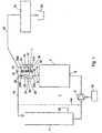
- FIG. 1 With reference numeral 1 is indicated an apparatus for preparing a beverage suitable for consumption such as coffee on the basis of a hot liquid such as water.
- an apparatus for preparing a café crème is involved.
- the apparatus is provided with a storage tank 2 which, in use, is filled with water.
- the apparatus is further provided with a heater 4 for heating water.
- An inlet 5 of the heater 4 is connected via pump 6 to the storage tank 2.
- the pump 6 pumps water from the storage tank to the heater 4.
- the apparatus is further provided with a three-way valve 7 which is provided with an inlet 8, a first outlet 10 and a second outlet 12.
- One outlet 14 of the heater is connected via a duct 16 to the inlet 8 of the three-way valve 7.
- the first outlet 10 is in fluid communication with the storage tank 2.
- the second outlet 12 is in fluid communication with a beverage preparing unit 22 known per se such as, for instance, of the type described in European patent application 0 878 158.
- This beverage preparing unit 22 known per se can for instance be filled with ground coffee for preparing, while supplying hot water under pressure, a café crème. This can then be collected in a mug 24 as is schematically shown in Fig. 1.
- the three-way valve 7 is provided with a first member 26 which, under the influence of a liquid flow from the inlet to the first outlet and/or the second outlet, is freely moveable between a first extreme position 26A and a second extreme position 26B.
- the first outlet 10 is provided with a sealing ring 28, schematically represented in Fig. 1, which, when the first member 26 is in the second extreme position 26B, causes a liquid flow path extending from the inlet to the first outlet to be closed off or blocked at the first outlet.
- the three-way valve is further provided with a second member 30 which, under the influence of a liquid flow from the inlet to the second outlet, is freely moveably between a third extreme position SOA and a fourth extreme position 30B.
- a second member 30 which, under the influence of a liquid flow from the inlet to the second outlet, is freely moveably between a third extreme position SOA and a fourth extreme position 30B.
- the three-way valve is disposed in one single housing.
- the three-way valve is provided with a first compartment 84 in which the first member is situated and a second compartment 36 in which the second member 30is situated.
- the first compartment 34 is provided with the inlet 8 and the first outlet 10.
- the second compartment is provided with the second outlet 12.
- the first and second compartment are separated from each other by means of a dividing wall 40.
- the first and second compartment are connected to each other by means of a fluid communication 42 extending through the dividing wall.
- the dividing wall 40 is provided with an inflow opening 44 which forms an extremity of the fluid communication 42.
- the fluid communication 42 reaches for a part from the inflow opening 44 into the second compartment 36, which tube is closed off at its free extremity and is provided at its upper side with an outflow opening 45 which outflow opening carries the sealing ring 32 and which opening is closed off by the second member 30 when the second member is in the third extreme position which is defined by the upper side of the fluid communication 42 mentioned in the second compartment.
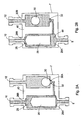
- the first member 26 and the first compartment 34 are configured such that when the first member is in the second extreme position 26B (clearly visible in the alternative embodiment of Fig. 2b) wherein the first outlet is closed off, the liquid flow from the inlet to the second outlet extends through a part 46 of the first compartment which is located between the first member and the inlet. Also, it appears that the inflow opening 44 of the fluid communication of the first compartment is situated between the inlet 8 and the first outlet 10.
- the part 46 of the first compartment further comprises the respective inflow opening 44 of the fluid communication.
- the first member 26 is of cylindrical design.
- the second member 30 is of convex design and that the first member is heavier than the second member.
- the flow resistance of the first outflow 18 is smaller than the flow resistance of the second outflow 20 in combination with the beverage preparing unit 22.
- the operation of the apparatus described up to this point is as follows.
- the first member 26 In rest, the first member 26 is in the first extreme position 26A.
- the second member 30 is in the third extreme position 30A. Accordingly, there is a fluid communication from the inlet 8 to the first outlet 10 but a fluid communication from the second outlet 12 to the inlet 8 is blocked in that the second member is in the third extreme position. Also, a fluid communication is possible in the direction from the inlet to the second outlet.
- the pump 6 For preparing a cup of coffee, the pump 6 is started.
- the pump 6 pumps water from the storage tank 2 to the heater 4.
- the heater 4 heats this water and feeds this to the inlet 8 of the three-way valve 7.
- the hot water flows into the first compartment and will move in the direction of the first outlet 10. Also, the water will move from the inlet 8 via the fluid communication to the second outlet 12.
- the second member moves from the third extreme position to the fourth extreme position.
- the first member 26 will rapidly be moved to the second extreme position, thereby closing off the first outlet.
- the first member continues to close off the first outlet well.
- the expansion water will choose the line of least resistance and hence flow back via the first outlet 10 and the second outflow path 18 to the storage tank. Therefore, the expansion water is prevented from being fed via the second outlet 12 to the beverage preparing unit 22. As a result, the beverage preparing unit 22 will not drip. Further, due to the cessation of the flow from the inlet to the second outlet, the second member 30 will move to the third extreme position 30A. This also happens relatively rapidly.
- the second member 30, functioning as a check valve rapidly closes off the liquid flow path from the second outlet 12 to the inlet 8 when it takes the third extreme position, the second outflow path 20 is prevented from, emptying.
- this remains filled with water which is advantageous when a consecutive consumption needs to be prepared. If it had been filled with air, initially, an amount of air would be fed to the beverage preparing unit 22, which is not beneficial to the quality of the prepared product. Moreover, thus, a spread in the amount of brew and therefore also a spread in dry matter (taste) will vary. Now, conversely, this is prevented.
- the first member 26 is heavier than the second member, this firs member will fall back relatively rapidly and, consequently, leave the second extreme position relatively rapidly as described hereinabove.
- the first member is cylinder-shaped, having more flow resistance than a sphere, it will moreover be rapidly lifted upon supply of a fluid to the inlet 8 (and, due to its weight, fall back rapidly upon cessation of this supply).
- the flowed-through surface between the first member and the second compartment is smaller than with the second member and the second compartment, which also renders it possible for the first member to fall back more rapidly. Therefore, the first member leaving the second extreme position proceeds relatively rapidly because of the relatively heavy weight of the first member. Also, it proceeds rapidly because the convex second member constitutes a check valve with a relatively small flow resistance.
- the short fluid communication 42 and the single housing play an advantageous part herein.
- the invention is not limited in any manner to the embodiment outlined hereinabove.
- the water can also be returned to an underside of the storage tank or at the entrance of the pump 6. Both alternatives are indicated via the ducts 52 and 54, respectively.
- a second embodiment is represented in which corresponding parts are provided with the same reference numerals.
- the operation of the three-way valve according to Fig. 2A and 2B is entirely identical to the three-way valve of Fig. 1, so that a further explanation can be omitted.
- a third embodiment of a three-way valve according to the invention is shown, suitable to be used in the apparatus according to Fig. 1.
- parts corresponding with Fig. 1 and Fig. 2 are provided with the same reference numerals as in Fig. 1 and Fig. 2.
- the three-way valve 7 according to Figs. 3a to 3g is also provided with the inlet 8, the first outlet 10 and the second outlet 12.
- the inlet 8 is connected by means of a fluid communication 8 to the first compartment 34. Further, the inlet 8 is connected by means of a fluid communication 48, 51 to the second compartment 36.
- the first member 26 is designed as a freely moveable circumferential edge 26 of a first umbrella valve 52.
- the three-way valve is provided with a first seat 54 for the first umbrella valve 52.
- the first umbrella valve 52 is connected to the first seat 54 by means of a stem 56 of the first umbrella valve.
- a sealing ring 59 is disposed between the first seat 54 and a housing 58 of the three-way valve.
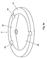
- Fig. 3c shows a front view of the first seat 54 with the first umbrella valve 52 in the direction of the arrow p of Fig. 3a.
- the first seat is provided with at least one and in this example a number of grooves 60 (see also Fig. 3d).
- Fig. 3d it appears that in the first seat at least one, and in this example a number of flow-through openings 62 are provided as well as a mounting opening 64 through which the stem 56 of the first umbrella valve 52 extends.
- the first umbrella valve itself is also shown.
- the freely moveable circumferential edge 26 (the first member) abuts against the first seat as shown in Figs. 3a, 3b and 3c.
- the circumferential edge 26 reaches over the grooves 60 so that between the circumferential edge 26 and the grooves 60 a now-through opening 66 is formed (see Fig. 3c).
- This flow-through opening 66 provides for a fluid communication between the inlet 8 and the first outlet 10. This means that when the first member 26 is in the first extreme position, the first outlet is not closed off and that the liquid can flow from the inlet 8 to the first outlet 10.
- the first umbrella valve is located in a liquid flow path extending between the inlet and the first outlet. Further, it holds that the first umbrella valve has a convex outer surface 68 facing away from the first outlet 10. Hence, the convex outer surface is directed against the flow direction from the inlet to the first outlet.
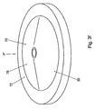
- the second member 30 is designed as a freely moveable circumferential edge 30 of a second umbrella valve 70.
- the three-way valve is further provided with a second seat 72 for the second umbrella valve 70.
- the second umbrella valve 70 is connected to the second seat 72 by means of a stem 74 of the second umbrella valve 70.
- a sealing 76 is located between the second seat 72 and the housing 58 of the three-way valve.
- the second seat 72 corresponds to the first seat 54, the difference being that the second seat 72 is not provided with grooves 60.
- a front view in the direction of the arrow p' of the second umbrella valve 70 with the second seat 72 is shown in Fig. 3f.
- a front view according to Fig. 3f wherein the second umbrella valve 70 has been left out is shown in Fig. 3g.
- the second seat 72 too is therefore provided with flow-through opening 62 and a mounting opening 64 through which the stem 74 extends.
- the second umbrella valve has a convex outer surface facing the second outlet.
- the convex outer surface 78 of the second umbrella valve is directed in the flow direction from the inlet to the second outlet.
- the second member (the circumferential edge 30 of the second umbrella valve 70) is shown in the third extreme position.
- the circumferential edge 30 of the second umbrella valve abuts against the second seat 72. This blocks a liquid flow from the second outlet in the direction of the inlet 8.
- an intermediate space is present between the circumferential edge 30 and the second seat 72.
- the circumferential edge 26 When an increasing liquid flow is supplied to the inlet 8, the circumferential edge 26, as already discussed, will start moving from the first extreme position towards the second extreme position. As a result, eventually, the first outlet 8 will be closed off. Also, under the influence of the fluid flow, due to the three-way valve the second circumferential edge 30 will move towards the fourth extreme position. In the fourth extreme position the second circumferential edge 80 lies completely clear of the seat 72. This is what is meant by the fourth extreme position. Hence, in that case, the circumferential edge 30 moves in the direction of the arrow v as shown in Fig. 3b. Consequently, the fluid can flow from the inlet 8 to the second outlet 12.
- the first member 26 In rest, the first member 26 is in the first extreme position while the flow-through openings 66 are cleared. Also, the second member is in the third extreme position wherein a liquid flow from the second outlet 12 towards the inlet 8 is blocked. Accordingly, there is a fluid communication present from the inlet to the first outlet and that a fluid communication from the second outlet 12 to the inlet 8 is blocked by the second member located in the third extreme position. A fluid communication from the inlet to the second outlet is also possible.
- the pump 6 When the pump 6 is started, the hot water flows into the first compartment and will move in the direction of the first outlet 10. The water will also move from the inlet 8 to the second outlet 12. As a consequence of the flow which arises, the first circumferential edge 26 will be moved to the second extreme position and hence close off the first outlet.
- the second circumferential edge 30 then moves from the third extreme position to the fourth extreme position so that the fluid can flow from the inlet to the second outlet.
- the beverage suitable for consumption then prepared by the beverage preparing unit is fed to the mug 24.
- the pump 6 is stopped, no longer a large flow rate is fed by tho heater to the inlet 8 of the three-way valve.
- the pressure in the first compartment 34 decreases.
- the first circumferential edge 26 is no longer kept in the second position.
- the first circumferential edge 26 then moves from the second position to the first position. The moment this happens, the first inlet 10 is no longer blocked. This means that the expansion water from the heater can be directly returned via the first outflow path 18 to the storage tank.
- the invention is not limited in any way to the exemplary embodiments outlined hereinabove.
- the hot water instead of coffee, with the aid of the hot water also other beverages such as cocoa and tea can be prepared.
- the heater 4 can be omitted so that also cold beverages such as ice tea can be prepared.
Landscapes
- Engineering & Computer Science (AREA)
- General Engineering & Computer Science (AREA)
- Mechanical Engineering (AREA)
- Food Science & Technology (AREA)
- Devices For Dispensing Beverages (AREA)
- Apparatus For Making Beverages (AREA)
- Tea And Coffee (AREA)
Claims (23)
- Gerät (1) zur Zubereitung mindestens einer Art von zum Verzehr geeigneten Getränks wie z.B. Kaffee oder Kakao auf der Basis einer heißen Flüssigkeit wie Wasser mit einem Vorratstank (2), der im Gebrauch mit einer Flüssigkeit wie Wasser gefüllt wird, einer Heizelement (4) und einem Dreiwegeventil (7), wobei das Dreiwegeventil (7) mit einem Einlass (8), einem ersten Auslass (10) und einem zweiten Auslass (12) versehen ist, wobei eine Pumpe (6) in Fluidverbindung mit dem Vorratstank (2) und einem Einlass (5) des Heizelements (4) zum Pumpen der Flüssigkeit von den Vorratstank (2) zu dem Heizelement (4) steht und wobei ein Auslass (14) des Heizelements (4) in Fluidverbindung mit dem Einlass (8) des Dreiwegeventils (7) steht, wobei der erste Auslass (10) des Dreiwegeventils (7) über einen ersten Abflussweg (11) in Fluidverbindung mit dem Vorratstank (2) und/oder einem Einlass der Pumpe zum Zurückführen der Flüssigkeit von dem Dreiwegeventil (7) zu dem Vorratstank (2) und/oder der Pumpe (6) steht und wobei der zweite Auslass (12) des Dreiwegeventils (7) über einen zweiten Abflussweg (20) mit einer Getränkezubereitungseinheit (22) zur Zubereitung eines zum Verzehr geeigneten Getränks auf der Basis einer heißen Flüssigkeit in Fluidverbindung steht, wobei das Dreiwegeventil (7) mit einem ersten Bauelement (26) versehen ist, das unter dem Einfluss einer Flüssigkeitsströmung von dem Einlass zu dem ersten Auslass und/oder dem zweiten Auslass zwischen einer ersten und einer zweiten Extremposition (26A, 26B) frei beweglich ist, wobei sich das erste Bauelement (26) unter dem Einfluss der Flüssigkeitsströmung von dem Einlass zu dem ersten Auslass und/oder dem zweiten Auslass von der ersten Extremposition in Richtung der zweiten Extremposition bewegen kann, und, in der zweiten Extremposition, den ersten Auslass absperrt, sodass die Flüssigkeitsströmung dann von dem Einlass zu dem zweiten Auslass verläuft, dadurch gekennzeichnet, dass das Dreiwegeventil (7) außerdem mit einem zweiten Bauelement (30) versehen ist, das unter dem Einfluss einer Flüssigkeitsströmung von dem Einlass zu dem zweiten Auslass zwischen einer dritten und vierten Extremposition (30A, 30B) frei beweglich ist, wobei sich das zweite Bauelement (30) unter dem Einfluss der Flüssigkeitsströmung von dem Einlass zu dem zweiten Auslass von der dritten Extremposition bis zu der vierten Extremposition bewegen kann und in der dritten Extremposition eine Flüssigkeitsströmung von dem zweiten Auslass in Richtung zu dem Einlass blockiert.
- Gerät nach Anspruch 1, dadurch gekennzeichnet, dass das Dreiwegeventil (7) in einem einzigen Gehäuse angeordnet ist.
- Gerät nach Anspruch 1 oder 2, dadurch gekennzeichnet, dass das Dreiwegeventil (7) mit einer ersten Kammer (34), in der sich das erste Bauelement (26) befindet, und mit einer zweiten Kammer (36), in der sich das zweite Bauelement (30) befindet, und einer Fluidverbindung (42) zwischen der ersten und zweiten Kammer versehen ist.
- Gerät nach Anspruch 3, dadurch gekennzeichnet, dass die erste Kammer (34) mit dem Einlass und dem ersten Auslass versehen ist.
- Gerät nach Anspruch 3 oder 4, dadurch gekennzeichnet, dass die zweite Kammer (36) mit dem zweiten Auslass versehen ist.
- Gerät nach Anspruch 4 und 5, dadurch gekennzeichnet, dass sich eine Einlauföffnung (44) der Fluidverbindung (42) in der ersten Kammer zwischen dem Einlass und dem ersten Auslass befindet.
- Gerät nach Anspruch 6, dadurch gekennzeichnet, dass das erste Bauelement (26) und die erste Kammer (34) so konfiguriert sind, dass, wenn sich das erste Bauelement in der zweiten Extremposition befindet und der erste Auslass gesperrt ist, eine Flüssigkeitsströmung von dem Einlass zu dem zweiten Auslass durch einen Teil der ersten Kammer, der sich zwischen dem ersten Bauelement und dem Einlass befindet, verläuft.
- Gerät nach einem der Ansprüche 3 bis 7, dadurch gekennzeichnet, dass die erste und zweite Kammer voneinander mittels einer Trennwand (40) getrennt sind, wobei die Fluidverbindung durch die Trennwand verläuft.
- Gerät nach Anspruch 7 und 8, dadurch gekennzeichnet, dass der genannte Teil der ersten Kammer die Einlauföffnung der Fluidverbindung (42) umfasst.
- Gerät nach einem der vorhergehenden Ansprüche, dadurch gekennzeichnet, dass das Dreiwegeventil eine Flüssigkeitsströmung von dem Einlass zu dem ersten Auslass erlaubt, wenn das erste Bauelement nicht in der zweiten Extremposition ist.
- Gerät nach einem der vorhergehenden Ansprüche, dadurch gekennzeichnet, dass das Dreiwegeventil eine Flüssigkeitsströmung von dem Einlass zu dem zweiten Auslass erlaubt, wenn das zweite Bauelement nicht in der dritten Extremposition ist.
- Gerät nach einem der vorhergehenden Ansprüche, dadurch gekennzeichnet, dass das erste Bauelement ein zylindrisches Design hat.
- Gerät nach einem der vorhergehenden Ansprüche, dadurch gekennzeichnet, dass das zweite Bauelement ein konvexes Design hat.
- Gerät nach einem der vorhergehenden Ansprüche, dadurch gekennzeichnet, dass das erste Bauelement schwerer als das zweite Bauelement ist.
- Gerät nach einem der vorhergehenden Ansprüche, dadurch gekennzeichnet, dass ein Strömungswiderstand des ersten Ablaufs geringer als ein Strömungswiderstand des zweiten Ablaufs in Kombination mit der Getränkezubereitungseinheit ist.
- Gerät nach einem der vorhergehenden Ansprüche 1 bis 11, dadurch gekennzeichnet, dass das erste Bauelement als eine frei bewegliche Umfangskante eines ersten flexiblen Schirmventils (52) designt ist und das Dreiwegeventil mit einem ersten Sitz (54) für das erste Schirmventit (52) versehen ist, wobei das erste Schirmventil (52) mit dem ersten Sitz (54) verbunden ist und der erste Sitz mindestes mit mindestens einer Rinne (60) versehen ist, wobei die Umfangskante des ersten Schirmventils in der ersten Extremposition gegen den ersten Sitz stößt und über die Rinne reicht, sodass zwischen der Umfangskante des ersten Schirmventils und der Rinne ein Zwischenraum (66) vorhanden ist, wobei der Zwischenraum eine Flüssigkeitsströmung von dem Einlass zu dem ersten Auslass freigibt und wobei die Umfangskante des ersten Schirmventils in der zweiten Extremposition gegen den ersten Sitz stößt und sich in die Rinne erstreckt, sodass die Umfangskante den ersten Einlass sperrt.
- Gerät nach Anspruch 16, dadurch gekennzeichnet, dass die Umlaufkante des ersten Schirmventils (52) in der zweiten Extremposition gegen den Sitz und den Boden der Rinne stößt.
- Gerät nach Anspruch 16 oder 17, dadurch gekennzeichnet, dass sich das erste Schirmventil in einem Flüssigkeitsströmungsweg befindet, der zwischen dem Einlass und dem ersten Auslass verläuft.
- Gerät nach Anspruch 18, dadurch gekennzeichnet, dass das erste Schirmventil eine konvexe äußere Oberfläche (68) hat, die dem ersten Auslass abgewandt ist.
- Gerät nach einem der vorhergehenden Ansprüche 1 bis 12 oder 16 bis 19, dadurch gekennzeichnet, dass das zweite Bauelement als eine frei bewegliche Umfangskante (30) eines zweiten flexiblen Schirmventils (70) designt ist und das Dreiwegeventil mit einem zweiten Sitz (72) für das zweite Schirmventil (70) versehen ist, wobei das zweite Schirmventil (70) mit dem zweiten Sitz (72) verbunden ist, wobei die Umfangskante des zweiten Schirmventils in der dritten Extremposition gegen den zweiten Sitz stößt und eine Flüssigkeitsströmung von dem zweiten Auslass in Richtung zu dem Einlass blockiert und wobei in der vierten Extremposition zwischen der Umfangskante des zweiten Schirmventils und dem zweiten Sitz ein Zwischenraum vorhanden ist.
- Gerät nach Anspruch 20, dadurch gekennzeichnet, dass sich das erste Schirmventil in einem Flüssigkeitsströmungsweg befindet, der zwischen dem Einlass und dem zweiten Auslass verläuft.
- Gerät nach Anspruch 21, dadurch gekennzeichnet, dass das zweite Schirmventil eine konvexe äußere Oberfläche (78) hat, die dem zweiten Auslass zugewandt ist.
- Gerät nach einem der vorhergehenden Ansprüche, dadurch gekennzeichnet, dass von dem Einlass zu dem ersten Bauelement und von dem Einlass zu dem zweiten Bauelement unverschließbare Fluidströmungswege vorhanden sind.
Applications Claiming Priority (3)
| Application Number | Priority Date | Filing Date | Title |
|---|---|---|---|
| NL1018247A NL1018247C2 (nl) | 2001-06-08 | 2001-06-08 | Inrichting voor het bereiden van een voor consumptie geschikte drank zoals koffie. |
| NL1018247 | 2001-06-08 | ||
| PCT/NL2002/000377 WO2002100227A1 (en) | 2001-06-08 | 2002-06-10 | Apparatus for preparing a beverage suitable for consumption, such as coffee |
Publications (2)
| Publication Number | Publication Date |
|---|---|
| EP1404202A1 EP1404202A1 (de) | 2004-04-07 |
| EP1404202B1 true EP1404202B1 (de) | 2006-03-08 |
Family
ID=19773517
Family Applications (1)
| Application Number | Title | Priority Date | Filing Date |
|---|---|---|---|
| EP02736287A Expired - Lifetime EP1404202B1 (de) | 2001-06-08 | 2002-06-10 | Verfahren, system und vorrichtung zur zubereitung einer getränkeportion, z.b. von kaffee |
Country Status (8)
| Country | Link |
|---|---|
| US (2) | US7415921B2 (de) |
| EP (1) | EP1404202B1 (de) |
| CN (1) | CN1268266C (de) |
| AT (1) | ATE319364T1 (de) |
| DE (1) | DE60209716T2 (de) |
| ES (1) | ES2257552T3 (de) |
| NL (1) | NL1018247C2 (de) |
| WO (1) | WO2002100227A1 (de) |
Families Citing this family (36)
| Publication number | Priority date | Publication date | Assignee | Title |
|---|---|---|---|---|
| WO2005004684A1 (en) * | 2003-07-15 | 2005-01-20 | Koninklijke Philips Electronics N.V. | Beverage maker suitable for use at high altitudes |
| DE10334545A1 (de) * | 2003-07-29 | 2005-02-17 | Pav Patentverwertung Kg | Kaffeebrühvorrichtung mit Überlauf |
| US7640845B2 (en) * | 2005-09-12 | 2010-01-05 | Keurig, Incorporated | Drain for beverage forming machine |
| DE102006006785B4 (de) * | 2006-02-14 | 2008-07-03 | BSH Bosch und Siemens Hausgeräte GmbH | Heizsystem mit Rückführung |
| US20080041231A1 (en) * | 2006-08-17 | 2008-02-21 | The Procter & Gamble Company | Method and device for brewing beverages |
| ITFI20070028A1 (it) * | 2007-02-07 | 2008-08-08 | Saeco Ipr Ltd | Dispositivo di infusione per la preparazione di bevande da capsule monodose con un dispositivo di centraggio delle capsule. |
| TWM317236U (en) * | 2007-03-27 | 2007-08-21 | Klub Mfg Corp | Two-in-one drink making machine |
| JP5451597B2 (ja) * | 2007-05-31 | 2014-03-26 | コーニンクレッカ フィリップス エヌ ヴェ | 貯水槽及び貯水槽の排出開口のサイズを決定するための部材を持つ飲料作成器 |
| US8180204B2 (en) * | 2007-07-02 | 2012-05-15 | Brewl Technologies, Inc. | Hot beverage brewing apparatus |
| DE602008004073D1 (de) * | 2008-01-02 | 2011-02-03 | Emparanza Y Glados Internac S A | Kaffeemaschine mit Druckablassventil |
| FR2927788B1 (fr) * | 2008-02-27 | 2013-02-08 | Seb Sa | Robinet pour distribuer les aliments contenus dans un recipient et appareil electromenager de preparation culinaire muni d'un tel robinet |
| DK2317898T3 (da) * | 2008-07-14 | 2012-10-15 | Nestec Sa | Vandcirkulationssystem til en driktilberedningsindretning |
| ES2313855B1 (es) * | 2008-07-21 | 2010-03-17 | Electrodomesticos Taurus, S.L. | Valvula de despresurizacion para maquina de preparacion de cafe. |
| DE102009034234B4 (de) * | 2009-07-23 | 2013-06-13 | Wmf Württembergische Metallwarenfabrik Ag | Getränkeautomat |
| US8511221B2 (en) * | 2009-11-05 | 2013-08-20 | Gruppo Cimbali S.P.A. | Apparatus for preparing and dispensing a beverage, in particular a chocolate-based beverage in a coffee machine |
| ES2382789B1 (es) * | 2009-11-18 | 2013-05-06 | Jofemar, S.A. | Sistema de caldera y distribuidor para una maquina expendedora de bebidas calientes |
| US20110174168A1 (en) * | 2010-01-21 | 2011-07-21 | AMF Automation Technologies, LLC d/b/a AMF Bakery Systems | Dough Pump and Developer |
| DE102010030103A1 (de) * | 2010-06-15 | 2011-12-15 | BSH Bosch und Siemens Hausgeräte GmbH | Heißgetränkezubereitungsmaschine mit Energierückgewinnung |
| IT1402572B1 (it) * | 2010-11-12 | 2013-09-13 | Rpe Srl | Elettrovalvola a tre vie per un circuito di alimentazione di un fluido, in particolare per una macchina per la preparazione di bevande a base di caffe' o similari |
| US9723945B2 (en) * | 2010-11-26 | 2017-08-08 | Koninklijke Philips N.V. | Device for making a beverage adapted to accurately set a dispense temperature of the beverage |
| ITMI20111514A1 (it) * | 2011-08-08 | 2013-02-09 | Brasilia Spa | Macchina da caffe' professionale o domestica |
| US9795245B2 (en) * | 2012-03-14 | 2017-10-24 | Hamilton Beach Brands, Inc. | Kitchen appliance for preparing a beverage and method of operating same |
| CN102987922A (zh) * | 2012-12-18 | 2013-03-27 | 宁波美侬咖啡机有限公司 | 一种咖啡机 |
| US9521924B2 (en) | 2013-12-24 | 2016-12-20 | Pangaea Labs Ltd. | Brewable beverage making machine |
| CN104188534B (zh) * | 2014-03-13 | 2017-11-10 | 泛世开发所有限公司 | 可冲饮饮料制作机 |
| KR101433602B1 (ko) | 2014-05-21 | 2014-08-26 | 주식회사 크로버 | 회전식 추출챔버를 구비한 음료생성장치 |
| USD760008S1 (en) | 2014-07-08 | 2016-06-28 | Clover Co., Ltd. | Beverage machine |
| CN110785108B (zh) * | 2017-05-12 | 2023-08-04 | 纽威澳大利亚有限公司 | 具有定量机构的浓缩咖啡机 |
| WO2018226633A1 (en) * | 2017-06-05 | 2018-12-13 | Keurig Green Mountain, Inc. | Pressure relief valve configuration for beverage machine |
| CN109419364A (zh) * | 2017-08-28 | 2019-03-05 | 博西华电器(江苏)有限公司 | 阀体以及具有该阀体的咖啡机 |
| CN110081602A (zh) * | 2019-04-27 | 2019-08-02 | 广东亿龙电器科技有限公司 | 一种泄残留水气装置 |
| US20220186852A1 (en) * | 2020-12-14 | 2022-06-16 | B/E Aerospace, Inc. | Venting devices for aircraft brewing apparatus |
| GB202104739D0 (en) * | 2021-04-01 | 2021-05-19 | Medincell | Device |
| US12369744B1 (en) | 2024-01-18 | 2025-07-29 | Sharkninja Operating Llc | Preparation of beverage machines for cold beverage brewing |
| WO2025155323A1 (en) | 2024-01-18 | 2025-07-24 | Sharkninja Operating Llc | Preventing coffee bean grinder jamming |
| US12575692B2 (en) | 2024-01-18 | 2026-03-17 | Sharkninja Operating Llc | Suggesting coffee bean grind size for beverage machines |
Family Cites Families (13)
| Publication number | Priority date | Publication date | Assignee | Title |
|---|---|---|---|---|
| GB1170878A (en) * | 1968-05-20 | 1969-11-19 | Atrol Armaturen Gmbh | Valve device for preventing a backflow between a removal line and a supply line feeding this. |
| GB2108486B (en) | 1981-10-26 | 1986-01-29 | Farmos Group Ltd | Alkane and alkene derivatives and their preparation and use |
| US4729401A (en) * | 1987-01-29 | 1988-03-08 | Burron Medical Inc. | Aspiration assembly having dual co-axial check valves |
| IT1243337B (it) * | 1990-07-13 | 1994-06-10 | Rancilio Macchine Caffe | Macchina per caffe' espresso |
| US5267506A (en) * | 1993-01-13 | 1993-12-07 | Zhihua Cai | Apparatus for automatic coffee brewing |
| DK0676163T3 (da) * | 1994-04-08 | 2001-09-10 | Schaerer Ag M | Kaffemaskine, især husholdningskaffemaskine |
| DE19549227A1 (de) * | 1995-12-30 | 1997-07-03 | Braun Ag | Brühgetränkezubereitungsmaschine |
| CH690161A5 (de) * | 1996-03-25 | 2000-05-31 | Arthur Schmed | Filterkaffeemaschine. |
| NL1006034C2 (nl) | 1997-05-13 | 1998-11-16 | Marinus Barbara Arnoldus Maria | Hangelement. |
| GB9709647D0 (en) | 1997-05-14 | 1997-07-02 | Mainetti Uk Ltd | Garment display frame |
| FR2786138B1 (fr) * | 1998-07-28 | 2001-01-19 | Plastic Omnium Cie | Clapet anti-retour pour reservoir a carburant |
| EP1074207B1 (de) * | 1999-08-04 | 2005-05-18 | Gruppo Cimbali S.p.A. | Espressokaffeemaschine |
| US6481339B1 (en) * | 1999-10-26 | 2002-11-19 | Newco Enterprises, Inc. | Coffee brewer |
-
2001
- 2001-06-08 NL NL1018247A patent/NL1018247C2/nl not_active IP Right Cessation
-
2002
- 2002-06-10 EP EP02736287A patent/EP1404202B1/de not_active Expired - Lifetime
- 2002-06-10 ES ES02736287T patent/ES2257552T3/es not_active Expired - Lifetime
- 2002-06-10 US US10/480,075 patent/US7415921B2/en not_active Expired - Lifetime
- 2002-06-10 DE DE60209716T patent/DE60209716T2/de not_active Expired - Lifetime
- 2002-06-10 WO PCT/NL2002/000377 patent/WO2002100227A1/en not_active Ceased
- 2002-06-10 CN CNB028156404A patent/CN1268266C/zh not_active Expired - Fee Related
- 2002-06-10 AT AT02736287T patent/ATE319364T1/de not_active IP Right Cessation
-
2008
- 2008-04-02 US US12/061,522 patent/US8011290B2/en not_active Expired - Fee Related
Also Published As
| Publication number | Publication date |
|---|---|
| EP1404202A1 (de) | 2004-04-07 |
| NL1018247C2 (nl) | 2002-12-10 |
| WO2002100227A1 (en) | 2002-12-19 |
| US7415921B2 (en) | 2008-08-26 |
| ATE319364T1 (de) | 2006-03-15 |
| US8011290B2 (en) | 2011-09-06 |
| CN1268266C (zh) | 2006-08-09 |
| CN1541076A (zh) | 2004-10-27 |
| US20080184896A1 (en) | 2008-08-07 |
| DE60209716T2 (de) | 2006-09-21 |
| US20050003052A1 (en) | 2005-01-06 |
| ES2257552T3 (es) | 2006-08-01 |
| DE60209716D1 (de) | 2006-05-04 |
Similar Documents
| Publication | Publication Date | Title |
|---|---|---|
| EP1404202B1 (de) | Verfahren, system und vorrichtung zur zubereitung einer getränkeportion, z.b. von kaffee | |
| US7021197B2 (en) | Hot beverage machine | |
| US9414711B2 (en) | Coffee machine | |
| US9125521B2 (en) | Combined multiple beverage brewing apparatus and brewing basket for use in same | |
| US6405637B1 (en) | Fluid delivery system for generating pressure pulses to make beverages | |
| US8910564B2 (en) | Electrical appliance for preparing, storing and dispensing hot beverages | |
| AU625112B2 (en) | Appliance for brewing coffee/tea | |
| US20080028944A1 (en) | Multiple beverage brewer | |
| EP3713458B1 (de) | Maschine zur zubereitung von getränken und verfahren zur steuerung | |
| US20200100619A1 (en) | Brewing device for preparing a hot beverage and associated method | |
| CA2687193A1 (en) | Beverage brewing apparatus with pump dispensing system | |
| EP2109386B1 (de) | Kaffeemaschinenstruktur zur zubereitung von heissgetränken | |
| CA3058599A1 (en) | Steam dispensing apparatus for hot beverage preparation | |
| JP7653439B2 (ja) | 吐出装置を有する飲料調製装置 | |
| US20250031897A1 (en) | Coffee machine for preparing coffee with highly flexible use | |
| CN100566639C (zh) | 用于制备饮料的装置 | |
| US20050241487A1 (en) | Heated substance reservoir baffle | |
| RU2829723C2 (ru) | Слив воды для ополаскивания из заварочной камеры устройства для приготовления напитка | |
| CN223627339U (zh) | 饮品机及冲泡装置 | |
| CN120304699A (zh) | 饮料机的饮料分配单元以及饮料机 | |
| EP3501347A1 (de) | Getränkespender mit mehreren auflösungskammern |
Legal Events
| Date | Code | Title | Description |
|---|---|---|---|
| PUAI | Public reference made under article 153(3) epc to a published international application that has entered the european phase |
Free format text: ORIGINAL CODE: 0009012 |
|
| 17P | Request for examination filed |
Effective date: 20040108 |
|
| AK | Designated contracting states |
Kind code of ref document: A1 Designated state(s): AT BE CH CY DE DK ES FI FR GB GR IE IT LI LU MC NL PT SE TR |
|
| AX | Request for extension of the european patent |
Extension state: AL LT LV MK RO SI |
|
| 17Q | First examination report despatched |
Effective date: 20041028 |
|
| GRAP | Despatch of communication of intention to grant a patent |
Free format text: ORIGINAL CODE: EPIDOSNIGR1 |
|
| GRAS | Grant fee paid |
Free format text: ORIGINAL CODE: EPIDOSNIGR3 |
|
| GRAA | (expected) grant |
Free format text: ORIGINAL CODE: 0009210 |
|
| AK | Designated contracting states |
Kind code of ref document: B1 Designated state(s): AT BE CH CY DE DK ES FI FR GB GR IE IT LI LU MC NL PT SE TR |
|
| PG25 | Lapsed in a contracting state [announced via postgrant information from national office to epo] |
Ref country code: NL Free format text: LAPSE BECAUSE OF FAILURE TO SUBMIT A TRANSLATION OF THE DESCRIPTION OR TO PAY THE FEE WITHIN THE PRESCRIBED TIME-LIMIT Effective date: 20060308 Ref country code: LI Free format text: LAPSE BECAUSE OF FAILURE TO SUBMIT A TRANSLATION OF THE DESCRIPTION OR TO PAY THE FEE WITHIN THE PRESCRIBED TIME-LIMIT Effective date: 20060308 Ref country code: FI Free format text: LAPSE BECAUSE OF FAILURE TO SUBMIT A TRANSLATION OF THE DESCRIPTION OR TO PAY THE FEE WITHIN THE PRESCRIBED TIME-LIMIT Effective date: 20060308 Ref country code: CH Free format text: LAPSE BECAUSE OF FAILURE TO SUBMIT A TRANSLATION OF THE DESCRIPTION OR TO PAY THE FEE WITHIN THE PRESCRIBED TIME-LIMIT Effective date: 20060308 Ref country code: AT Free format text: LAPSE BECAUSE OF FAILURE TO SUBMIT A TRANSLATION OF THE DESCRIPTION OR TO PAY THE FEE WITHIN THE PRESCRIBED TIME-LIMIT Effective date: 20060308 Ref country code: BE Free format text: LAPSE BECAUSE OF FAILURE TO SUBMIT A TRANSLATION OF THE DESCRIPTION OR TO PAY THE FEE WITHIN THE PRESCRIBED TIME-LIMIT Effective date: 20060308 |
|
| REG | Reference to a national code |
Ref country code: GB Ref legal event code: FG4D |
|
| REG | Reference to a national code |
Ref country code: CH Ref legal event code: EP |
|
| REG | Reference to a national code |
Ref country code: IE Ref legal event code: FG4D |
|
| REF | Corresponds to: |
Ref document number: 60209716 Country of ref document: DE Date of ref document: 20060504 Kind code of ref document: P |
|
| PG25 | Lapsed in a contracting state [announced via postgrant information from national office to epo] |
Ref country code: DK Free format text: LAPSE BECAUSE OF FAILURE TO SUBMIT A TRANSLATION OF THE DESCRIPTION OR TO PAY THE FEE WITHIN THE PRESCRIBED TIME-LIMIT Effective date: 20060608 Ref country code: SE Free format text: LAPSE BECAUSE OF FAILURE TO SUBMIT A TRANSLATION OF THE DESCRIPTION OR TO PAY THE FEE WITHIN THE PRESCRIBED TIME-LIMIT Effective date: 20060608 |
|
| PG25 | Lapsed in a contracting state [announced via postgrant information from national office to epo] |
Ref country code: IE Free format text: LAPSE BECAUSE OF NON-PAYMENT OF DUE FEES Effective date: 20060612 |
|
| PG25 | Lapsed in a contracting state [announced via postgrant information from national office to epo] |
Ref country code: MC Free format text: LAPSE BECAUSE OF NON-PAYMENT OF DUE FEES Effective date: 20060630 |
|
| REG | Reference to a national code |
Ref country code: ES Ref legal event code: FG2A Ref document number: 2257552 Country of ref document: ES Kind code of ref document: T3 |
|
| PG25 | Lapsed in a contracting state [announced via postgrant information from national office to epo] |
Ref country code: PT Free format text: LAPSE BECAUSE OF FAILURE TO SUBMIT A TRANSLATION OF THE DESCRIPTION OR TO PAY THE FEE WITHIN THE PRESCRIBED TIME-LIMIT Effective date: 20060808 |
|
| NLV1 | Nl: lapsed or annulled due to failure to fulfill the requirements of art. 29p and 29m of the patents act | ||
| REG | Reference to a national code |
Ref country code: CH Ref legal event code: PL |
|
| ET | Fr: translation filed | ||
| PLBE | No opposition filed within time limit |
Free format text: ORIGINAL CODE: 0009261 |
|
| STAA | Information on the status of an ep patent application or granted ep patent |
Free format text: STATUS: NO OPPOSITION FILED WITHIN TIME LIMIT |
|
| 26N | No opposition filed |
Effective date: 20061211 |
|
| PG25 | Lapsed in a contracting state [announced via postgrant information from national office to epo] |
Ref country code: GR Free format text: LAPSE BECAUSE OF FAILURE TO SUBMIT A TRANSLATION OF THE DESCRIPTION OR TO PAY THE FEE WITHIN THE PRESCRIBED TIME-LIMIT Effective date: 20060609 |
|
| PG25 | Lapsed in a contracting state [announced via postgrant information from national office to epo] |
Ref country code: LU Free format text: LAPSE BECAUSE OF NON-PAYMENT OF DUE FEES Effective date: 20060610 Ref country code: TR Free format text: LAPSE BECAUSE OF FAILURE TO SUBMIT A TRANSLATION OF THE DESCRIPTION OR TO PAY THE FEE WITHIN THE PRESCRIBED TIME-LIMIT Effective date: 20060308 |
|
| PG25 | Lapsed in a contracting state [announced via postgrant information from national office to epo] |
Ref country code: CY Free format text: LAPSE BECAUSE OF FAILURE TO SUBMIT A TRANSLATION OF THE DESCRIPTION OR TO PAY THE FEE WITHIN THE PRESCRIBED TIME-LIMIT Effective date: 20060308 |
|
| REG | Reference to a national code |
Ref country code: ES Ref legal event code: PC2A Owner name: KONINKLIJKE DOUWE EGBERTS B.V. Effective date: 20140630 |
|
| REG | Reference to a national code |
Ref country code: GB Ref legal event code: 732E Free format text: REGISTERED BETWEEN 20140717 AND 20140723 |
|
| REG | Reference to a national code |
Ref country code: DE Ref legal event code: R082 Ref document number: 60209716 Country of ref document: DE Representative=s name: VOLMER, GEORG, DIPL.-ING., DE |
|
| REG | Reference to a national code |
Ref country code: DE Ref legal event code: R081 Ref document number: 60209716 Country of ref document: DE Owner name: KONINKLIJKE DOUWE EGBERTS B.V., NL Free format text: FORMER OWNER: SARA LEE/DE N.V., UTRECHT, NL Effective date: 20141009 Ref country code: DE Ref legal event code: R082 Ref document number: 60209716 Country of ref document: DE Representative=s name: VOLMER, GEORG, DIPL.-ING., DE Effective date: 20141009 Ref country code: DE Ref legal event code: R082 Ref document number: 60209716 Country of ref document: DE Representative=s name: MEISSNER BOLTE PATENTANWAELTE RECHTSANWAELTE P, DE Effective date: 20141009 |
|
| REG | Reference to a national code |
Ref country code: FR Ref legal event code: TP Owner name: SARA LEE/DE N.V., NL Effective date: 20141017 |
|
| REG | Reference to a national code |
Ref country code: FR Ref legal event code: PLFP Year of fee payment: 15 |
|
| REG | Reference to a national code |
Ref country code: DE Ref legal event code: R082 Ref document number: 60209716 Country of ref document: DE Representative=s name: MEISSNER BOLTE PATENTANWAELTE RECHTSANWAELTE P, DE |
|
| REG | Reference to a national code |
Ref country code: FR Ref legal event code: PLFP Year of fee payment: 16 |
|
| REG | Reference to a national code |
Ref country code: FR Ref legal event code: PLFP Year of fee payment: 17 |
|
| PGFP | Annual fee paid to national office [announced via postgrant information from national office to epo] |
Ref country code: GB Payment date: 20190627 Year of fee payment: 18 Ref country code: ES Payment date: 20190725 Year of fee payment: 18 |
|
| PGFP | Annual fee paid to national office [announced via postgrant information from national office to epo] |
Ref country code: IT Payment date: 20200618 Year of fee payment: 19 |
|
| GBPC | Gb: european patent ceased through non-payment of renewal fee |
Effective date: 20200610 |
|
| PG25 | Lapsed in a contracting state [announced via postgrant information from national office to epo] |
Ref country code: GB Free format text: LAPSE BECAUSE OF NON-PAYMENT OF DUE FEES Effective date: 20200610 |
|
| PGFP | Annual fee paid to national office [announced via postgrant information from national office to epo] |
Ref country code: DE Payment date: 20210628 Year of fee payment: 20 Ref country code: FR Payment date: 20210625 Year of fee payment: 20 |
|
| REG | Reference to a national code |
Ref country code: ES Ref legal event code: FD2A Effective date: 20211027 |
|
| PG25 | Lapsed in a contracting state [announced via postgrant information from national office to epo] |
Ref country code: ES Free format text: LAPSE BECAUSE OF NON-PAYMENT OF DUE FEES Effective date: 20200611 |
|
| REG | Reference to a national code |
Ref country code: DE Ref legal event code: R071 Ref document number: 60209716 Country of ref document: DE |
|
| PG25 | Lapsed in a contracting state [announced via postgrant information from national office to epo] |
Ref country code: IT Free format text: LAPSE BECAUSE OF NON-PAYMENT OF DUE FEES Effective date: 20210610 |