EP1404254B1 - Stentzuführvorrichtung mit gleitmechanismus - Google Patents
Stentzuführvorrichtung mit gleitmechanismus Download PDFInfo
- Publication number
- EP1404254B1 EP1404254B1 EP02734627A EP02734627A EP1404254B1 EP 1404254 B1 EP1404254 B1 EP 1404254B1 EP 02734627 A EP02734627 A EP 02734627A EP 02734627 A EP02734627 A EP 02734627A EP 1404254 B1 EP1404254 B1 EP 1404254B1
- Authority
- EP
- European Patent Office
- Prior art keywords
- skid
- skids
- retractable sheath
- medical device
- device delivery
- Prior art date
- Legal status (The legal status is an assumption and is not a legal conclusion. Google has not performed a legal analysis and makes no representation as to the accuracy of the status listed.)
- Expired - Lifetime
Links
Images



Classifications
-
- A—HUMAN NECESSITIES
- A61—MEDICAL OR VETERINARY SCIENCE; HYGIENE
- A61F—FILTERS IMPLANTABLE INTO BLOOD VESSELS; PROSTHESES; DEVICES PROVIDING PATENCY TO, OR PREVENTING COLLAPSING OF, TUBULAR STRUCTURES OF THE BODY, e.g. STENTS; ORTHOPAEDIC, NURSING OR CONTRACEPTIVE DEVICES; FOMENTATION; TREATMENT OR PROTECTION OF EYES OR EARS; BANDAGES, DRESSINGS OR ABSORBENT PADS; FIRST-AID KITS
- A61F2/00—Filters implantable into blood vessels; Prostheses, i.e. artificial substitutes or replacements for parts of the body; Appliances for connecting them with the body; Devices providing patency to, or preventing collapsing of, tubular structures of the body, e.g. stents
- A61F2/95—Instruments specially adapted for placement or removal of stents or stent-grafts
- A61F2/962—Instruments specially adapted for placement or removal of stents or stent-grafts having an outer sleeve
- A61F2/966—Instruments specially adapted for placement or removal of stents or stent-grafts having an outer sleeve with relative longitudinal movement between outer sleeve and prosthesis, e.g. using a push rod
-
- A—HUMAN NECESSITIES
- A61—MEDICAL OR VETERINARY SCIENCE; HYGIENE
- A61F—FILTERS IMPLANTABLE INTO BLOOD VESSELS; PROSTHESES; DEVICES PROVIDING PATENCY TO, OR PREVENTING COLLAPSING OF, TUBULAR STRUCTURES OF THE BODY, e.g. STENTS; ORTHOPAEDIC, NURSING OR CONTRACEPTIVE DEVICES; FOMENTATION; TREATMENT OR PROTECTION OF EYES OR EARS; BANDAGES, DRESSINGS OR ABSORBENT PADS; FIRST-AID KITS
- A61F2/00—Filters implantable into blood vessels; Prostheses, i.e. artificial substitutes or replacements for parts of the body; Appliances for connecting them with the body; Devices providing patency to, or preventing collapsing of, tubular structures of the body, e.g. stents
- A61F2/95—Instruments specially adapted for placement or removal of stents or stent-grafts
Definitions
- Stents are used to maintain the patency of bodily vessels such as coronary, mesentery, peripheral, or cerebral vasculature, veins, the gastrointestinal tract, the biliary tract, the urethra, the trachea, hepatic shunts and fallopian tubes. Stents are delivered to desired locations in bodily vessel via catheters. Examples of catheters are disclosed in US 5,772,669 and US 6,036,697.
- Catheter 100 comprises inner tube 104, stent 108 disposed about inner tube 104 toward the distal end of the catheter and retractable sheath 114 which is disposed about stent 108.
- Retractable sheath 114 is maintained in place over stent 108 during stent delivery to protect the bodily vessel from the stent and to generally facilitate stent delivery.
- Pull collar 115 is affixed to retractable sheath 114 and pull wire 113 extends proximally from pull collar 115.
- retractable sheath 114 may be retracted by pulling on pull wire 113. The stent may thus be exposed for expansion and implantation in the desired region of the vessel.
- Other types of retraction mechanisms are also known in the art.
- the retractable sheath may dimple or become partially embedded in portions of the stent, in particular where the stent is self-expanding. As shown in Fig. 1, portions 117 of retractable sheath 114 protrude in between struts 116 of stent 108 hampering the retraction of the sheath from over the stent and risking damage to the stent.
- the problems of dimpling and/or embedding of the stent are exacerbated as thinner sheaths are used. While it is desirable to employer thinner retractable sheaths to ensure flexibility of the catheter in the region of the retractable sheath and to maintain a low catheter profile, the use of thinner sheaths increases the likelihood of dimpling and/or embedding. Dimpling of the retractable sheath and/or embedding of the retractable sheath increases the forces required to retract the sheath. Moreover, where thinner sheaths are used, loading a stent may prove difficult as a result of buckling of the sheath.
- EP-A-1 025 813 discloses a stent delivery apparatus for a self-expanding stent.
- the apparatus has an outer sheath which is an elongated tubular member with distal and proximal ends.
- the outer sheath has an enlarged section adjacent its distal end and extends along the apparatus until a luer hub.
- the sheath is made of a composite structure incorporating an inner polytetrafluoroethylene layer, an outer polyamide layer and a middle stainless steel braid wire layer.
- EP-A-1 064 888 discloses a stent keeper for a self-expanding stent. This apparatus is made of two coaxially provided tubes with the inner tube within the outer tube.
- the technical problem of the invention is to improve a stent delivery system such that dimpling of the retractable sheath and/or embedding of the stent impact on the choice of material for the sheath is avoided.
- the instant invention is directed in one embodiment to a medical device delivery catheter comprising an inner member and a retractable sheath assembly disposed about the inner member.
- the retractable sheath assembly comprises an outer sheath of a first material and one or more skids.
- the skids comprise an outer layer of a first skid material and an inner layer of a second skid material.
- the second skid material is different from the first skid material.
- the retractable sheath assembly is constructed and arranged such that the skids are disposed between the outer sheath and the inner member prior to, during and subsequent to retraction of the retractable sheath assembly.
- the catheter further comprises a stent or other medical device disposed about the inner member with the retractable sheath assembly disposed about the stent.
- the first skid material is harder than the second skid material, desirably as measured using the Shore D hardness scale.
- the second skid material is more slippery than the first skid material, desirably as measured by the coefficient of friction. Even more desirably, the first skid material is harder than the second skid material and the second skid material is more slippery than the first skid material.
- the first skid material may be a hard polymeric material such as polyimide and the second skid material is a slippery polymeric material such as PTFE.
- suitable materials for the second skid material include ceramics, amorphous carbon - desirably in the form of diamond like coatings and ceramic - for example AlO.
- the second skid material may line the entire interior of the sheath or may be provided in the form of skids which are adjacent one another and spaced from one another.
- the invention is directed to a medical device delivery catheter comprising an inner member and a retractable sheath assembly disposed about the inner member, the retractable sheath assembly having a bending flexibility of at least 1.17 GPa.
- the retractable sheath assembly includes one or more skids.
- the skids comprise an outer skid layer of a first skid material and an inner skid layer of a second skid material.
- the outer skid layer may optionally have a shore D hardness of at least 84.
- the one or more skids are disposed between the sheath and the inner member.
- the retractable sheath assembly further comprises a sheath disposed about the skids and attached thereto.
- Fig. 1 is a schematic illustration of a prior art catheter.
- Fig. 2 is a schematic illustration of the distal end an inventive catheter.
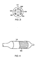
- Fig. 3 is a transverse cross-sectional view of the inventive catheter of Fig. 2 taken along line 3-3.
- Fig. 4 is a schematic illustration of the distal end an inventive catheter with parts of the sheath cut away.
- Fig. 5 is a schematic illustration of skids in the form of a tube with fingers for use in the inventive catheters.
- Fig. 6 is a transverse cross-sectional view of the inventive skids of Fig. 5 taken along line 6-6.
- Fig. 7 is a schematic illustration of inventive spiral skids for use in the inventive catheters.
- Figure 8 is a perspective view with parts cut away of inventive skids affixed to an inner member with a ferrule.
- Figure 9 is a side view with parts cut away of inventive skids affixed to an inner member with a ferrule.
- the invention is directed to a medical device delivery catheter, the distal end of which is shown in Fig. 2.
- the catheter comprises inner member 104 and retractable sheath assembly 112 disposed about inner member 104.
- inner member 104 is in the form of a tube.
- Inner member 104 may also be a solid, elongate structure, as for example, in the case of a fixed-wire catheter.
- Inner member 104 terminates in tip 106.
- Retractable sheath assembly 112 is disposed about optional stent 108.
- Other medical devices may also be provided.
- the catheter may further comprise one or more bumpers (not shown) and one or more marker bands (not shown) as are known in the art. The use of bumpers and marker bands is disclosed in US 5,989,280 as well as elsewhere in the art.
- retractable sheath assembly 112 includes sheath 114 and at least one and desirably a plurality of skids 122.
- Skids 122 comprise an outer layer 124 of a first skid material and an inner layer 128 of a second skid material. The second skid material is different from the first skid material.
- the retractable sheath assembly is constructed and arranged such that the skids are disposed between the sheath and the inner member prior to, during and subsequent to retraction of the retractable sheath assembly.
- the stent is not shown contacting the skids in Figs. 2 and 3, the stent may rest against the skids, in particular where a self-expanding stent is used.
- Sheath 114 may be made of one or more polymeric materials. Suitable polymeric materials include polyethylene, medical grade nylon, hytrel and polyether-based polyamides such as Pebax. Where Pebax is used, desirably the Pebax has a durometer of 70D or less. Other suitable materials include other balloon materials including compliant and non-compliant materials as are known in the art.
- the first skid material may be polymeric.
- Suitable polymers include liquid crystal polymers (LCP) such as Vectran, polyetheretherketone (PEEK), polyimides including polyether imides, polysulfones, and high durometer nylon.
- LCP liquid crystal polymers
- PEEK polyetheretherketone
- polyimides including polyether imides
- polysulfones and high durometer nylon.
- Other suitable first skid materials include metals such as stainless steel and composite materials, for example, carbon fiber reinforced film or tape.
- the second skid material may be polymeric.
- the second skid material may be PTFE or fluorinated ethylene polymer (FEP).
- FEP fluorinated ethylene polymer
- suitable materials for the second skid material include ceramics, amorphous carbon - desirably in the form of diamond like coatings, and ceramic - for example A10.
- the second skid material will have a coefficient of static friction of 0.1 or less on steel and more desirably, 0.04 or less on steel.
- the first skid material is harder than the second skid material as measured on the Shore D hardness scale.
- the second skid material is more slippery than the first skid material, desirably as measured by the coefficient of friction.
- the first skid material may be a hard polymeric material such as polyimide and the second skid material may be a slippery polymeric material such as PTFE.
- first and second skid materials and their relative thicknesses are chosen such that the skids are stiff enough to span the openings in a stent without protruding therein.
- first and second skid materials and their relative thicknesses are chosen such that the stent does not impress appreciably, if at all, in the skids.
- the skids may line the entire interior of the sheath or only a portion of the sheath. For example, a plurality of spaced apart skids may be provided.
- the invention contemplates providing any number of skids. In one embodiment, a single skid is provided. In other embodiments, two, three, four, five, six, seven, eight, nine, ten or more skids are provided.
- skids 122 extend from sheath 114 at junctions 130. As shown in Fig. 2, skids 122 do not dimple or become partially embedded in the openings of the stent.
- skids 122 are in the form of a tube 12 with a plurality of fingers 123 separated by gaps 131.
- the fingers may be straight, curved or have straight and curved portions.
- each finger 123 includes an outer layer 124 of a first skid material and an inner layer 128 of a second skid material.
- the first skid material may be any of the first skid materials disclosed above and the second skid material may be any of the second skid materials disclosed above.
- Fingers 123 extend from collar 129.
- Collar 129 is desirably as short as possible.
- collar is 5 mm in length or less and more suitably, 3 mm or less.
- Collar 129 may be attached to sheath 114 at one or more locations. Desirably, collar 129 is positioned over a proximal or distal end portion of the medical device being delivered by the catheter.
- Figs. 4-6 may desirably be employed in conjunction with a retractable sheath assembly which is retracted via a pull wire.
- pull wire 113 extends proximally from collar 129.
- skids 122 are arranged in a spiral.
- the pitch of the skids is substantially similar, if not identical, to the pitch of the stent where the stent is of spiral or helical construction.
- each skid is attached to the tube with fingers at a single point as shown at 130 in Fig. 2.
- the skids are attached at a plurality of locations to the tube having fingers.
- the entirety of the skids is attached to the outer layer.
- Skids 122 may be bonded to sheath 114 adhesively. Suitable adhesives include UV curable adhesives such as methyl methacrylate as well as other adhesives such as epoxy, polyurethane and cyanoacrylate. Other techniques for bonding the skids to the sheath include heat bonding and laser welding techniques including those disclosed in WO 02/20081.
- the skids may also be crimped to the sheath and held in place with ferrule 141 as shown in Figs. 8 and 9.
- Ferrule 141 is disposed about retractable sheath 114, skids 122, inner member 104 and, optionally, support tube 143.
- Support tube 143 may optionally be provided at the distal end of inner member 104 for additional support.
- the optional support tube may be disposed about inner member 104 or interior to inner member 104.
- a rigid marker band may also be used to hold together the sheath and skids.
- the individual skids are 0.13 cm (0.050 inches) wide or less. Also desirably, adjacent skids are separated by 0.013cm (0.005 inches) or more. Where three skids are provided, the skids are desirably 0.11cm (0.045 inches) wide or less and adjacent skids are separated by 0.013cm (0.005 inches) or more. As the number of skids is increased, desirably the width of the skids is decreased. In one desirable embodiment, the individual skids are 0.06cm (0.025 inches) wide or less and adjacent skids are separated by 0.013cm (0.005 inches) or more. Desirably, the distance between adjacent skids will be sufficient to prevent interference between adjacent skids when the catheter is flexed in the region of the retractable sheath assembly.
- the retractable sheath assembly is 0.004 inches thick or less and more desirably 0.002 inches thick or less. Most desirably, the retractable sheath assembly is 0.001 inches thick or less.
- the skids are desirably no more than 0.002 inches thick with the first skid material being no more than 0.001 inches thick and the second skid material being no more than 0.001 inches thick. Thicker skids may be appropriate under certain circumstances, for example, where very high expansion forces are encountered or where thick walled stents with large gaps are employed. Even more desirably, the skids are no more than 0.001 inches thick.
- the second skid material is made of PTFE
- the PTFE is desirably no more than 0.001 inches thick and more desirably no more than 0.0001 inches thick.
- amorphous carbon, perylene or ceramic is used as the second skid material, the material is desirably no more than 1 ⁇ thick.
- the invention is directed to a medical device catheter comprising an inner member and a retractable sheath assembly disposed about the inner member where the retractable sheath assembly has a bending flexibility of at least 1.17 GPa.
- the retractable sheath assembly comprises a plurality of skids. The skids are disposed between the outer layer and the inner member. Any of the skid constructions and geometries disclosed above may be used.
- the retractable sheath assembly may be retracted via the use of a pull wire or any other suitable retraction mechanism.
- a stent or other medical device may be disposed between the inner member and the skids.
- the skids may be the only covering over the optional medical device or the retractable sheath assembly may further comprise a sheath disposed about the skids and attached to the skids in one or more locations.
- the interior of the retractable sheath or exterior of the skids may be provided with an optional lubricious coating.
- Suitable lubricious coatings include silicones, lipids and hydrogels.
- any of the coatings disclosed in US 5,693,034 may be used. The coating may be used to facilitate bending of the catheter in the region of the retractable sheath by allowing the skids to slide relative to the retractable sheath.
- inventive medical device delivery systems may be provided in over-the-wire form as disclosed above as well as in fixed-wire and rapid exchange form.
- the inner member will typically be in the form of a tube.
- the inner member will typically be a solid, elongate structure. Additional details concerning rapid exchange and fixed-wire catheters may be found in US 5,980,533 and US 5,702,364.
- the inventive catheters may be used in delivering medical devices such as prostheses to any suitable bodily vessel including coronary, mesentery, peripheral, or cerebral vasculature, veins, the gastrointestinal tract, the biliary tract, the urethra, the trachea, hepatic shunts and fallopian tubes.
- the prostheses may be stents, stent-grafts, grafts, vena cava filters or other implantable medical devices.
- the stents are desirably self-expanding. Balloon expandable stents may also be delivered using the inventive medical device delivery catheters disclosed herein.
- the catheter may further comprise one or more socks disposed about the distal and/or proximal end of the stent.
- the socks may optionally be radiopaque. Additional details concerning socks may be found in US 6,554,841.
- a retractable sheath assembly may be made by preparing a polyimide tube, the inner diameter of which is lined with PTFE.
- the tube may be made by dipping coating a mandril with PTFE and subsequently, dip coating the PTFE coated mandril in polyimide.
- the mandril may be dip coated with one coat or, desirably, multiple coats of polyimide.
- the tube may then be laser cut, chemically etched, mechanically cut or otherwise cut to provide a plurality of skids with a desired spacing.
- the mandril may be removed from the tube prior to or subsequent to cutting the tube.
- the process may be carried by first dipping the mandril in the other polymer or material to form the inner layer of the skid.
- the inner layer may be dip coated with any other suitable material.
- the process may be modified by providing a preformed inner member of the inner material and dip coating the member to provide the outer layers of material necessary to form the skids.
- the skids may also be formed coextruding the outer skid layer and the inner skid layer on an mandril.
- any suitable stiff, rigid thermoplastic liquid crystal polymer LCP
- LCP liquid crystal polymer
- suitable outer skid layer materials include fiberglass, polyetheretherketone (PEEK) and polyetherimide.
- suitable materials for the inner skid layer include fluorinated ethylene polymer (FEP) and other fluorinated polymers.
- FEP fluorinated ethylene polymer
- the resulting member may then be cut using any of the techniques disclosed above to provide the skids.
- skids used in the inventive catheters include extrusion processes such as ram extrusion, polymeric casting techniques such as solvent casting and film casting, molding techniques such as blow molding, injection molding and rotational molding. Also, coating and/or plating processes including chemical vapor deposition, plasma based depositions, physical vapor deposition and electroplating may also be used in forming the skids.
- the skids may then be bonded to a retractable sheath to form a retractable sheath assembly via any of the techniques disclosed above including adhesive bonding, laser welding and crimping with a ferrule.
- the retractable sheath assembly may then be incorporated into the construction of a catheter using known techniques for catheter construction.
Landscapes
- Health & Medical Sciences (AREA)
- Engineering & Computer Science (AREA)
- Biomedical Technology (AREA)
- Cardiology (AREA)
- Oral & Maxillofacial Surgery (AREA)
- Transplantation (AREA)
- Heart & Thoracic Surgery (AREA)
- Vascular Medicine (AREA)
- Life Sciences & Earth Sciences (AREA)
- Animal Behavior & Ethology (AREA)
- General Health & Medical Sciences (AREA)
- Public Health (AREA)
- Veterinary Medicine (AREA)
- Media Introduction/Drainage Providing Device (AREA)
- Materials For Medical Uses (AREA)
Claims (16)
- Ein Katheter für die Implantation eines medizinischen Geräts, der ein inneres Element (104) und eine zurückziehbare Hüllenbaugruppe (112), die um das innere Element herum angeordnet ist, umfasst und dadurch gekennzeichnet ist, dass die zurückziehbare Hüllenbaugruppe eine zurückziehbare Hülle (114) und ein oder mehrere Gleitelemente (122) aufweist, die sich von der zurückziehbaren Hülle aus erstrecken, wobei die Gleitelemente zwischen der zurückziehbaren Hülle (114) und dem inneren Element (104) angeordnet sind und jedes Gleitelement (122) eine äußere Schicht (124) eines ersten Gleitelementmaterials und eine innere Schicht (128) eines zweiten Gleitelementmaterials, das von dem ersten Material verschieden ist, umfasst, und die innere Schicht dem inneren Element gegenüber liegt.
- Der Katheter für die Implantation eines medizinischen Geräts nach Anspruch 1, der weiter einen Stent (108) aufweist, der um das innere Element (104) herum angeordnet ist, wobei die zurückziehbare Hüllenbaugruppe um den Stent herum angeordnet ist.
- Der Katheter für die Implantation eines medizinischen Geräts nach Anspruch 1 oder 2, wobei die zurückziehbare Hüllenbaugruppe (112) so konstruiert und gegliedert ist, dass die Gleitelemente (122) vor, während und im Anschluss an den Rückzug der zurückziehbaren Hüllenbaugruppe zwischen der zurückziehbaren Hülle und dem inneren Element angeordnet sind.
- Der Katheter für die Implantation eines medizinischen Geräts nach Anspruch 1, wobei das erste Gleitelementmaterial härter ist als das zweite Material.
- Der Katheter für die Implantation eines medizinischen Geräts nach Anspruch 1, wobei das zweite Gleitelementmaterial einen niedrigeren Reibungskoeffizienten auf Stahl besitzt als das erste Gleitelementmaterial.
- Der Katheter für die Implantation eines medizinischen Geräts nach Anspruch 1, wobei das erste Gleitelementmaterial härter ist als das zweite Gleitelementmaterial und das zweite Gleitelementmaterial glatter ist als das erste Gleitelementmaterial.
- Der Katheter für die Implantation eines medizinischen Geräts nach Anspruch 1, wobei das erste Gleitelementmaterial Polyimid und das zweite Gleitelementmaterial PTFE ist.
- Der Katheter für die Implantation eines medizinischen Geräts nach Anspruch 4, der eine Vielzahl von Gleitelementen (122) aufweist, wobei Gleitelemente, die einander benachbart sind, voneinander beabstandet sind.
- Ein Katheter für die Implantation eines medizinischen Geräts nach einem der vorhergehenden Ansprüche, wobei die zurückziehbare Hüllenbaugruppe eine Dicke von nicht mehr als 50µm (0.002 inches) besitzt.
- Der Katheter für die Implantation eines medizinischen Geräts nach Anspruch 9, wobei die Gleitelemente an der zurückziehbaren Hülle angebracht sind.
- Das System für die Implantation eines medizinischen Geräts nach Anspruch 4, wobei das zweite Gleitelementmaterial glatter ist als das erste Gleitelementmaterial.
- Der Katheter für die Implantation eines medizinischen Geräts nach einem der vorhergehenden Ansprüche , wobei die zurückziehbare Hüllenbaugruppe eine Krümmungsflexibilität von zumindest 1.17 GPa besitzt.
- Der Katheter für die Implantation eines medizinischen Geräts nach Anspruch 12, wobei die zurückziehbare Hüllenbaugruppe ein Gleitelement aufweist und das Gleitelement eine äußere Schicht eines ersten Gleitelementmaterials besitzt, das eine Shore D Härte von mindestens 84 hat.
- Der Katheter für die Implantation eines medizinischen Geräts nach Anspruch 13, wobei das Gleitelement eine innere Schicht eines zweiten Gleitelementmaterials enthält und das Gleitelement zwischen der zurückziehbaren Hülle und dem inneren Element angeordnet ist.
- Der Katheter für die Implantation eines medizinischen Geräts nach jedem der Ansprüche 12 bis 14, der weiter einen Stent aufweist, der um das innere Element herum angeordnet ist, wobei die zurückziehbare Hüllenbaugruppe um den Stent herum angeordnet ist.
- Der Katheter für die Implantation eines medizinischen Geräts nach Anspruch 15, wobei der Stent selbst-expandierend ist.
Applications Claiming Priority (3)
| Application Number | Priority Date | Filing Date | Title |
|---|---|---|---|
| US682013 | 2001-07-09 | ||
| US09/682,013 US6645238B2 (en) | 2001-07-09 | 2001-07-09 | Skids stent delivery system |
| PCT/US2002/017329 WO2003005936A2 (en) | 2001-07-09 | 2002-05-31 | Skids stent delivery system |
Publications (2)
| Publication Number | Publication Date |
|---|---|
| EP1404254A2 EP1404254A2 (de) | 2004-04-07 |
| EP1404254B1 true EP1404254B1 (de) | 2006-07-19 |
Family
ID=24737818
Family Applications (1)
| Application Number | Title | Priority Date | Filing Date |
|---|---|---|---|
| EP02734627A Expired - Lifetime EP1404254B1 (de) | 2001-07-09 | 2002-05-31 | Stentzuführvorrichtung mit gleitmechanismus |
Country Status (7)
| Country | Link |
|---|---|
| US (1) | US6645238B2 (de) |
| EP (1) | EP1404254B1 (de) |
| JP (1) | JP4447316B2 (de) |
| AT (1) | ATE333248T1 (de) |
| CA (1) | CA2453144C (de) |
| DE (1) | DE60213247T2 (de) |
| WO (1) | WO2003005936A2 (de) |
Families Citing this family (43)
| Publication number | Priority date | Publication date | Assignee | Title |
|---|---|---|---|---|
| US20030050684A1 (en) * | 2001-09-10 | 2003-03-13 | Abrams Robert M. | Internal restraint for delivery of self-expanding stents |
| US20050021123A1 (en) | 2001-04-30 | 2005-01-27 | Jurgen Dorn | Variable speed self-expanding stent delivery system and luer locking connector |
| JP4350515B2 (ja) * | 2001-11-09 | 2009-10-21 | ルビコン・メデイカル・インコーポレイテツド | ステント搬送装置 |
| US7169170B2 (en) * | 2002-02-22 | 2007-01-30 | Cordis Corporation | Self-expanding stent delivery system |
| US20040006380A1 (en) * | 2002-07-05 | 2004-01-08 | Buck Jerrick C. | Stent delivery system |
| US20040193179A1 (en) | 2003-03-26 | 2004-09-30 | Cardiomind, Inc. | Balloon catheter lumen based stent delivery systems |
| US7771463B2 (en) | 2003-03-26 | 2010-08-10 | Ton Dai T | Twist-down implant delivery technologies |
| AU2004226464A1 (en) | 2003-03-26 | 2004-10-14 | Cardiomind, Inc. | Implant delivery technologies |
| US7651521B2 (en) | 2004-03-02 | 2010-01-26 | Cardiomind, Inc. | Corewire actuated delivery system with fixed distal stent-carrying extension |
| US7285130B2 (en) * | 2004-04-27 | 2007-10-23 | Boston Scientific Scimed, Inc. | Stent delivery system |
| JP5128946B2 (ja) * | 2004-05-21 | 2013-01-23 | ウィセル リサーチ インスティテュート インコーポレイテッド | 胚性幹細胞のフィーダー非依存性長期培養 |
| US20050273151A1 (en) * | 2004-06-04 | 2005-12-08 | John Fulkerson | Stent delivery system |
| US20060079863A1 (en) * | 2004-10-08 | 2006-04-13 | Scimed Life Systems, Inc. | Medical devices coated with diamond-like carbon |
| EP1915113B1 (de) * | 2005-08-17 | 2010-03-03 | C.R. Bard, Inc. | Stentabgabesystem mit variabler geschwindigkeit |
| US20070100414A1 (en) | 2005-11-02 | 2007-05-03 | Cardiomind, Inc. | Indirect-release electrolytic implant delivery systems |
| EP2359776B1 (de) | 2005-12-23 | 2018-01-17 | Cook Medical Technologies LLC | System zum Einsetzen einer Prothese |
| US8808346B2 (en) | 2006-01-13 | 2014-08-19 | C. R. Bard, Inc. | Stent delivery system |
| US11026822B2 (en) | 2006-01-13 | 2021-06-08 | C. R. Bard, Inc. | Stent delivery system |
| US9308105B2 (en) * | 2006-04-19 | 2016-04-12 | Cook Medical Technologies Llc | Delivery device for an endoluminal prosthesis |
| GB0615658D0 (en) | 2006-08-07 | 2006-09-13 | Angiomed Ag | Hand-held actuator device |
| EP2101661B1 (de) * | 2006-12-26 | 2016-03-02 | Cook Medical Technologies LLC | Trägersystem und schleuse für eine endoluminale prothese |
| GB0713497D0 (en) | 2007-07-11 | 2007-08-22 | Angiomed Ag | Device for catheter sheath retraction |
| CA2701576C (en) * | 2007-10-17 | 2016-06-21 | Angiomed Gmbh & Co. Medizintechnik Kg | Delivery system for a self-expanding device for placement in a bodily lumen |
| WO2009135934A1 (en) * | 2008-05-09 | 2009-11-12 | Angiomed Gmbh & Co. Medizintechnik Kg | Method of loading a stent into a sheath |
| GB0815339D0 (en) * | 2008-08-21 | 2008-10-01 | Angiomed Ag | Method of loading a stent into a sheath |
| GB0823658D0 (en) * | 2008-12-30 | 2009-02-04 | Angiomed Ag | Stent delivery device |
| GB0823716D0 (en) | 2008-12-31 | 2009-02-04 | Angiomed Ag | Stent delivery device with rolling stent retaining sheath |
| US8657870B2 (en) | 2009-06-26 | 2014-02-25 | Biosensors International Group, Ltd. | Implant delivery apparatus and methods with electrolytic release |
| JP5685256B2 (ja) | 2009-09-21 | 2015-03-18 | メドトロニック,インコーポレイテッド | ステント付き経カテーテル補綴心臓弁搬送システムおよび方法 |
| GB0921240D0 (en) | 2009-12-03 | 2010-01-20 | Angiomed Ag | Stent device delivery system and method of making such |
| GB0921237D0 (en) | 2009-12-03 | 2010-01-20 | Angiomed Ag | Stent device delivery system and method of making such |
| GB0921236D0 (en) * | 2009-12-03 | 2010-01-20 | Angiomed Ag | Stent device delivery system and method of making such |
| GB0921238D0 (en) | 2009-12-03 | 2010-01-20 | Angiomed Ag | Stent device delivery system and method of making such |
| GB201010766D0 (en) * | 2010-06-25 | 2010-08-11 | Angiomed Ag | Delivery system for a self-expanding implant |
| WO2012023978A2 (en) * | 2010-08-17 | 2012-02-23 | St. Jude Medical, Inc. | Delivery system for collapsible heart valve |
| GB201017834D0 (en) | 2010-10-21 | 2010-12-01 | Angiomed Ag | System to deliver a bodily implant |
| GB201020373D0 (en) | 2010-12-01 | 2011-01-12 | Angiomed Ag | Device to release a self-expanding implant |
| US9387106B2 (en) * | 2013-02-28 | 2016-07-12 | Medtronic Vascular, Inc. | Medical device delivery systems and methods of use thereof |
| US9867611B2 (en) * | 2013-09-05 | 2018-01-16 | St. Jude Medical, Cardiology Division, Inc. | Anchoring studs for transcatheter valve implantation |
| US10441449B1 (en) | 2018-05-30 | 2019-10-15 | Vesper Medical, Inc. | Rotary handle stent delivery system and method |
| US10449073B1 (en) | 2018-09-18 | 2019-10-22 | Vesper Medical, Inc. | Rotary handle stent delivery system and method |
| CN110192940A (zh) * | 2019-06-14 | 2019-09-03 | 苏州晶俊新材料科技有限公司 | 一种可降解输卵管支架 |
| US11219541B2 (en) | 2020-05-21 | 2022-01-11 | Vesper Medical, Inc. | Wheel lock for thumbwheel actuated device |
Family Cites Families (21)
| Publication number | Priority date | Publication date | Assignee | Title |
|---|---|---|---|---|
| US6071273A (en) | 1988-02-29 | 2000-06-06 | Scimed Life Systems, Inc. | Fixed wire dilatation balloon catheter |
| SE8803444D0 (sv) * | 1988-09-28 | 1988-09-28 | Medinvent Sa | A device for transluminal implantation or extraction |
| CA2100970A1 (en) | 1991-12-18 | 1993-06-19 | Paul J. Buscemi | Lubricous polyer network |
| DK0627201T3 (da) * | 1993-06-02 | 1999-04-26 | Schneider Europ Gmbh | Anordning til frigørelse af en selvekspanderende endoprotese |
| US5683451A (en) * | 1994-06-08 | 1997-11-04 | Cardiovascular Concepts, Inc. | Apparatus and methods for deployment release of intraluminal prostheses |
| US5571168A (en) * | 1995-04-05 | 1996-11-05 | Scimed Lifesystems Inc | Pull back stent delivery system |
| US5534007A (en) * | 1995-05-18 | 1996-07-09 | Scimed Life Systems, Inc. | Stent deployment catheter with collapsible sheath |
| US5681347A (en) * | 1995-05-23 | 1997-10-28 | Boston Scientific Corporation | Vena cava filter delivery system |
| US6312454B1 (en) | 1996-06-13 | 2001-11-06 | Nitinol Devices & Components | Stent assembly |
| US5772669A (en) | 1996-09-27 | 1998-06-30 | Scimed Life Systems, Inc. | Stent deployment catheter with retractable sheath |
| US6425898B1 (en) | 1998-03-13 | 2002-07-30 | Cordis Corporation | Delivery apparatus for a self-expanding stent |
| US5980533A (en) | 1998-06-09 | 1999-11-09 | Scimed Life Systems, Inc. | Stent delivery system |
| US6036697A (en) | 1998-07-09 | 2000-03-14 | Scimed Life Systems, Inc. | Balloon catheter with balloon inflation at distal end of balloon |
| US6270521B1 (en) * | 1999-05-21 | 2001-08-07 | Cordis Corporation | Stent delivery catheter system for primary stenting |
| US6168617B1 (en) * | 1999-06-14 | 2001-01-02 | Scimed Life Systems, Inc. | Stent delivery system |
| US6478814B2 (en) * | 1999-06-14 | 2002-11-12 | Scimed Life Systems, Inc. | Stent securement sleeves and optional coatings and methods of use |
| US6287329B1 (en) | 1999-06-28 | 2001-09-11 | Nitinol Development Corporation | Stent keeper for a self-expanding stent delivery system |
| US6213995B1 (en) * | 1999-08-31 | 2001-04-10 | Phelps Dodge High Performance Conductors Of Sc And Ga, Inc. | Flexible tubing with braided signal transmission elements |
| US6270522B1 (en) * | 1999-12-21 | 2001-08-07 | Advanced Cardiovascular Systems, Inc. | High pressure catheter balloon |
| US6554841B1 (en) * | 2000-09-22 | 2003-04-29 | Scimed Life Systems, Inc. | Striped sleeve for stent delivery |
| US7422579B2 (en) * | 2001-05-01 | 2008-09-09 | St. Jude Medical Cardiology Divison, Inc. | Emboli protection devices and related methods of use |
-
2001
- 2001-07-09 US US09/682,013 patent/US6645238B2/en not_active Expired - Fee Related
-
2002
- 2002-05-31 WO PCT/US2002/017329 patent/WO2003005936A2/en not_active Ceased
- 2002-05-31 JP JP2003511746A patent/JP4447316B2/ja not_active Expired - Fee Related
- 2002-05-31 EP EP02734627A patent/EP1404254B1/de not_active Expired - Lifetime
- 2002-05-31 AT AT02734627T patent/ATE333248T1/de not_active IP Right Cessation
- 2002-05-31 DE DE60213247T patent/DE60213247T2/de not_active Expired - Lifetime
- 2002-05-31 CA CA2453144A patent/CA2453144C/en not_active Expired - Fee Related
Also Published As
| Publication number | Publication date |
|---|---|
| DE60213247D1 (de) | 2006-08-31 |
| DE60213247T2 (de) | 2007-08-02 |
| ATE333248T1 (de) | 2006-08-15 |
| JP2004534594A (ja) | 2004-11-18 |
| CA2453144C (en) | 2010-05-11 |
| CA2453144A1 (en) | 2003-01-23 |
| JP4447316B2 (ja) | 2010-04-07 |
| US20030009174A1 (en) | 2003-01-09 |
| EP1404254A2 (de) | 2004-04-07 |
| WO2003005936A3 (en) | 2003-05-01 |
| US6645238B2 (en) | 2003-11-11 |
| WO2003005936A2 (en) | 2003-01-23 |
Similar Documents
| Publication | Publication Date | Title |
|---|---|---|
| CA2453144C (en) | Skids stent delivery system | |
| US11147700B2 (en) | Self-expanding stent delivery system | |
| EP1601402B1 (de) | Aussenschlauch mit mehrfacher gewebeeinlage | |
| US9993613B2 (en) | Guide extension catheter | |
| US7309349B2 (en) | Friction reducing lubricant for stent loading and stent delivery systems | |
| US10124148B2 (en) | Guide extension catheter with trackable tip and related methods of use | |
| EP1894594B1 (de) | Nichtfusierte Katheterkörperfunktion | |
| EP2252360B1 (de) | Ballonkatheter mit langlebigem spitzenabschnitt | |
| US20120116494A1 (en) | Implantable medical endoprosthesis delivery system | |
| AU2003200613B2 (en) | Self-expanding stent delivery system | |
| EP3735936B1 (de) | Dorn und verfahren zum bilden einer expandierbaren stentstruktur | |
| US20090312832A1 (en) | Slip layer delivery catheter | |
| US20180193605A1 (en) | Catheter assembly for delivering a medical device | |
| US20240009012A1 (en) | Stent Delivery System | |
| EP1324720B1 (de) | Befestigung einer haltehülse an einem katheter mittels schweissen | |
| US20180318551A1 (en) | Catheter with improved torque response |
Legal Events
| Date | Code | Title | Description |
|---|---|---|---|
| PUAI | Public reference made under article 153(3) epc to a published international application that has entered the european phase |
Free format text: ORIGINAL CODE: 0009012 |
|
| 17P | Request for examination filed |
Effective date: 20040123 |
|
| AK | Designated contracting states |
Kind code of ref document: A2 Designated state(s): AT BE CH CY DE DK ES FI FR GB GR IE IT LI LU MC NL PT SE TR |
|
| 17Q | First examination report despatched |
Effective date: 20040803 |
|
| GRAP | Despatch of communication of intention to grant a patent |
Free format text: ORIGINAL CODE: EPIDOSNIGR1 |
|
| GRAS | Grant fee paid |
Free format text: ORIGINAL CODE: EPIDOSNIGR3 |
|
| GRAA | (expected) grant |
Free format text: ORIGINAL CODE: 0009210 |
|
| AK | Designated contracting states |
Kind code of ref document: B1 Designated state(s): AT BE CH CY DE DK ES FI FR GB GR IE IT LI LU MC NL PT SE TR |
|
| PG25 | Lapsed in a contracting state [announced via postgrant information from national office to epo] |
Ref country code: IT Free format text: LAPSE BECAUSE OF FAILURE TO SUBMIT A TRANSLATION OF THE DESCRIPTION OR TO PAY THE FEE WITHIN THE PRESCRIBED TIME-LIMIT;WARNING: LAPSES OF ITALIAN PATENTS WITH EFFECTIVE DATE BEFORE 2007 MAY HAVE OCCURRED AT ANY TIME BEFORE 2007. THE CORRECT EFFECTIVE DATE MAY BE DIFFERENT FROM THE ONE RECORDED. Effective date: 20060719 Ref country code: LI Free format text: LAPSE BECAUSE OF FAILURE TO SUBMIT A TRANSLATION OF THE DESCRIPTION OR TO PAY THE FEE WITHIN THE PRESCRIBED TIME-LIMIT Effective date: 20060719 Ref country code: AT Free format text: LAPSE BECAUSE OF FAILURE TO SUBMIT A TRANSLATION OF THE DESCRIPTION OR TO PAY THE FEE WITHIN THE PRESCRIBED TIME-LIMIT Effective date: 20060719 Ref country code: FI Free format text: LAPSE BECAUSE OF FAILURE TO SUBMIT A TRANSLATION OF THE DESCRIPTION OR TO PAY THE FEE WITHIN THE PRESCRIBED TIME-LIMIT Effective date: 20060719 Ref country code: CH Free format text: LAPSE BECAUSE OF FAILURE TO SUBMIT A TRANSLATION OF THE DESCRIPTION OR TO PAY THE FEE WITHIN THE PRESCRIBED TIME-LIMIT Effective date: 20060719 |
|
| REG | Reference to a national code |
Ref country code: GB Ref legal event code: FG4D |
|
| REG | Reference to a national code |
Ref country code: CH Ref legal event code: EP |
|
| REG | Reference to a national code |
Ref country code: IE Ref legal event code: FG4D |
|
| REF | Corresponds to: |
Ref document number: 60213247 Country of ref document: DE Date of ref document: 20060831 Kind code of ref document: P |
|
| PG25 | Lapsed in a contracting state [announced via postgrant information from national office to epo] |
Ref country code: SE Free format text: LAPSE BECAUSE OF FAILURE TO SUBMIT A TRANSLATION OF THE DESCRIPTION OR TO PAY THE FEE WITHIN THE PRESCRIBED TIME-LIMIT Effective date: 20061019 Ref country code: DK Free format text: LAPSE BECAUSE OF FAILURE TO SUBMIT A TRANSLATION OF THE DESCRIPTION OR TO PAY THE FEE WITHIN THE PRESCRIBED TIME-LIMIT Effective date: 20061019 |
|
| PG25 | Lapsed in a contracting state [announced via postgrant information from national office to epo] |
Ref country code: ES Free format text: LAPSE BECAUSE OF FAILURE TO SUBMIT A TRANSLATION OF THE DESCRIPTION OR TO PAY THE FEE WITHIN THE PRESCRIBED TIME-LIMIT Effective date: 20061030 |
|
| PG25 | Lapsed in a contracting state [announced via postgrant information from national office to epo] |
Ref country code: PT Free format text: LAPSE BECAUSE OF FAILURE TO SUBMIT A TRANSLATION OF THE DESCRIPTION OR TO PAY THE FEE WITHIN THE PRESCRIBED TIME-LIMIT Effective date: 20061219 |
|
| ET | Fr: translation filed | ||
| PLBE | No opposition filed within time limit |
Free format text: ORIGINAL CODE: 0009261 |
|
| STAA | Information on the status of an ep patent application or granted ep patent |
Free format text: STATUS: NO OPPOSITION FILED WITHIN TIME LIMIT |
|
| 26N | No opposition filed |
Effective date: 20070420 |
|
| PG25 | Lapsed in a contracting state [announced via postgrant information from national office to epo] |
Ref country code: MC Free format text: LAPSE BECAUSE OF NON-PAYMENT OF DUE FEES Effective date: 20070531 |
|
| PG25 | Lapsed in a contracting state [announced via postgrant information from national office to epo] |
Ref country code: GR Free format text: LAPSE BECAUSE OF FAILURE TO SUBMIT A TRANSLATION OF THE DESCRIPTION OR TO PAY THE FEE WITHIN THE PRESCRIBED TIME-LIMIT Effective date: 20061020 |
|
| PG25 | Lapsed in a contracting state [announced via postgrant information from national office to epo] |
Ref country code: CY Free format text: LAPSE BECAUSE OF FAILURE TO SUBMIT A TRANSLATION OF THE DESCRIPTION OR TO PAY THE FEE WITHIN THE PRESCRIBED TIME-LIMIT Effective date: 20060719 Ref country code: LU Free format text: LAPSE BECAUSE OF NON-PAYMENT OF DUE FEES Effective date: 20070531 |
|
| PG25 | Lapsed in a contracting state [announced via postgrant information from national office to epo] |
Ref country code: TR Free format text: LAPSE BECAUSE OF FAILURE TO SUBMIT A TRANSLATION OF THE DESCRIPTION OR TO PAY THE FEE WITHIN THE PRESCRIBED TIME-LIMIT Effective date: 20060719 |
|
| PGFP | Annual fee paid to national office [announced via postgrant information from national office to epo] |
Ref country code: BE Payment date: 20100603 Year of fee payment: 9 |
|
| BERE | Be: lapsed |
Owner name: *BOSTON SCIENTIFIC LTD Effective date: 20110531 |
|
| PG25 | Lapsed in a contracting state [announced via postgrant information from national office to epo] |
Ref country code: BE Free format text: LAPSE BECAUSE OF NON-PAYMENT OF DUE FEES Effective date: 20110531 |
|
| REG | Reference to a national code |
Ref country code: FR Ref legal event code: CA Effective date: 20140513 |
|
| PGFP | Annual fee paid to national office [announced via postgrant information from national office to epo] |
Ref country code: GB Payment date: 20140528 Year of fee payment: 13 |
|
| PGFP | Annual fee paid to national office [announced via postgrant information from national office to epo] |
Ref country code: NL Payment date: 20140510 Year of fee payment: 13 Ref country code: DE Payment date: 20140528 Year of fee payment: 13 Ref country code: FR Payment date: 20140509 Year of fee payment: 13 |
|
| REG | Reference to a national code |
Ref country code: DE Ref legal event code: R082 Ref document number: 60213247 Country of ref document: DE Representative=s name: VOSSIUS & PARTNER PATENTANWAELTE RECHTSANWAELT, DE |
|
| REG | Reference to a national code |
Ref country code: DE Ref legal event code: R082 Ref document number: 60213247 Country of ref document: DE Representative=s name: VOSSIUS & PARTNER PATENTANWAELTE RECHTSANWAELT, DE |
|
| REG | Reference to a national code |
Ref country code: DE Ref legal event code: R082 Ref document number: 60213247 Country of ref document: DE Representative=s name: VOSSIUS & PARTNER PATENTANWAELTE RECHTSANWAELT, DE Effective date: 20141026 Ref country code: DE Ref legal event code: R082 Ref document number: 60213247 Country of ref document: DE Representative=s name: VOSSIUS & PARTNER PATENTANWAELTE RECHTSANWAELT, DE Effective date: 20150203 Ref country code: DE Ref legal event code: R081 Ref document number: 60213247 Country of ref document: DE Owner name: BOSTON SCIENTIFIC LIMITED, BM Free format text: FORMER OWNER: BOSTON SCIENTIFIC LTD., ST. MICHAEL, BARBADOS, BB Effective date: 20150203 |
|
| REG | Reference to a national code |
Ref country code: DE Ref legal event code: R119 Ref document number: 60213247 Country of ref document: DE |
|
| GBPC | Gb: european patent ceased through non-payment of renewal fee |
Effective date: 20150531 |
|
| REG | Reference to a national code |
Ref country code: NL Ref legal event code: MM Effective date: 20150601 |
|
| REG | Reference to a national code |
Ref country code: FR Ref legal event code: ST Effective date: 20160129 |
|
| PG25 | Lapsed in a contracting state [announced via postgrant information from national office to epo] |
Ref country code: NL Free format text: LAPSE BECAUSE OF NON-PAYMENT OF DUE FEES Effective date: 20150601 Ref country code: DE Free format text: LAPSE BECAUSE OF NON-PAYMENT OF DUE FEES Effective date: 20151201 Ref country code: GB Free format text: LAPSE BECAUSE OF NON-PAYMENT OF DUE FEES Effective date: 20150531 |
|
| PG25 | Lapsed in a contracting state [announced via postgrant information from national office to epo] |
Ref country code: FR Free format text: LAPSE BECAUSE OF NON-PAYMENT OF DUE FEES Effective date: 20150601 |
|
| PGFP | Annual fee paid to national office [announced via postgrant information from national office to epo] |
Ref country code: IE Payment date: 20190509 Year of fee payment: 18 |
|
| PG25 | Lapsed in a contracting state [announced via postgrant information from national office to epo] |
Ref country code: IE Free format text: LAPSE BECAUSE OF NON-PAYMENT OF DUE FEES Effective date: 20200531 |