EP1404417B1 - Brandschutzeinrichtung für haushaltgeräte - Google Patents
Brandschutzeinrichtung für haushaltgeräte Download PDFInfo
- Publication number
- EP1404417B1 EP1404417B1 EP02760178A EP02760178A EP1404417B1 EP 1404417 B1 EP1404417 B1 EP 1404417B1 EP 02760178 A EP02760178 A EP 02760178A EP 02760178 A EP02760178 A EP 02760178A EP 1404417 B1 EP1404417 B1 EP 1404417B1
- Authority
- EP
- European Patent Office
- Prior art keywords
- protection device
- fire protection
- gas sensor
- domestic appliance
- fault current
- Prior art date
- Legal status (The legal status is an assumption and is not a legal conclusion. Google has not performed a legal analysis and makes no representation as to the accuracy of the status listed.)
- Expired - Lifetime
Links
- 239000004020 conductor Substances 0.000 claims description 15
- 230000001960 triggered effect Effects 0.000 claims description 2
- 230000006378 damage Effects 0.000 abstract description 9
- 230000007257 malfunction Effects 0.000 abstract description 6
- 239000007789 gas Substances 0.000 description 18
- 239000000779 smoke Substances 0.000 description 6
- UGFAIRIUMAVXCW-UHFFFAOYSA-N Carbon monoxide Chemical compound [O+]#[C-] UGFAIRIUMAVXCW-UHFFFAOYSA-N 0.000 description 4
- 229910002091 carbon monoxide Inorganic materials 0.000 description 4
- 239000000460 chlorine Substances 0.000 description 4
- 238000010586 diagram Methods 0.000 description 4
- 239000004698 Polyethylene Substances 0.000 description 3
- 229920000573 polyethylene Polymers 0.000 description 3
- ZAMOUSCENKQFHK-UHFFFAOYSA-N Chlorine atom Chemical compound [Cl] ZAMOUSCENKQFHK-UHFFFAOYSA-N 0.000 description 2
- 239000004952 Polyamide Substances 0.000 description 2
- 239000004743 Polypropylene Substances 0.000 description 2
- 229910052801 chlorine Inorganic materials 0.000 description 2
- 238000010438 heat treatment Methods 0.000 description 2
- 239000000463 material Substances 0.000 description 2
- 239000004033 plastic Substances 0.000 description 2
- 229920003023 plastic Polymers 0.000 description 2
- 229920002647 polyamide Polymers 0.000 description 2
- -1 polyethylene Polymers 0.000 description 2
- 229920001155 polypropylene Polymers 0.000 description 2
- 230000001681 protective effect Effects 0.000 description 2
- 239000000126 substance Substances 0.000 description 2
- 239000004793 Polystyrene Substances 0.000 description 1
- 239000000919 ceramic Substances 0.000 description 1
- 239000003795 chemical substances by application Substances 0.000 description 1
- 238000001514 detection method Methods 0.000 description 1
- 238000011161 development Methods 0.000 description 1
- 230000018109 developmental process Effects 0.000 description 1
- 238000004519 manufacturing process Methods 0.000 description 1
- 239000004800 polyvinyl chloride Substances 0.000 description 1
- 229910052573 porcelain Inorganic materials 0.000 description 1
- 230000002265 prevention Effects 0.000 description 1
- 238000000926 separation method Methods 0.000 description 1
Images
Classifications
-
- A—HUMAN NECESSITIES
- A62—LIFE-SAVING; FIRE-FIGHTING
- A62C—FIRE-FIGHTING
- A62C3/00—Fire prevention, containment or extinguishing specially adapted for particular objects or places
- A62C3/16—Fire prevention, containment or extinguishing specially adapted for particular objects or places in electrical installations, e.g. cableways
Definitions
- the invention relates to a fire protection device for household appliances consisting of at least one residual current circuit breaker and at least one gas sensor with gas sensor circuit, wherein the at least one residual current circuit breaker is designed so that a fault current in one of the electrical conductors of the household appliance leads to a shutdown of the electrical supply of the household appliance and at least a gas sensor generates a signal above a certain amount of a guide gas within the household appliance, which also leads to a shutdown of the electrical supply of the household appliance.
- the self-contained or autonomous fire protection device of FR 2 543 839 for an electrical switching arrangement a residual current circuit breaker and a gas sensor, wherein the gas sensor generates a leakage current, which leads to the response of the residual current circuit breaker and triggered by this network separation of the electrical switching device.
- a device with a container for a fire extinguishing substance which opens automatically in the presence of a flame or when the ambient temperature rises above a threshold beyond the fire extinguishing substance indirectly or pour directly onto the fire-risk areas or parts of the device to be protected.
- the arrangement may be such that the container, preferably a plurality, each containing fire extinguishing cells, which conveniently have holes in the bottom area, of a protective cover or a z. B. membranous pellicles are completed, which is destroyed at a predetermined temperature for opening the holes and this can leak the fire extinguishing agent.
- the electric fire detection and fire prevention / fire extinguishing system of US 5,936,531 includes a sealed housing housing electrical circuitry coupled to a power supply, a spark sensor, a heat sensor and a smoke detector, and a fire extinguisher. Further, the system includes a control logic circuit coupled to the spark sensor, the heat sensor, the smoke detector, and the fire extinguisher. When a spark is detected by the spark sensor, the control logic circuit shuts off the power supply. When a heat rise from the heat sensor or smoke from the smoke detector is detected, the control logic circuit shuts off the power and activates the fire extinguisher.
- Object of the present invention is therefore to provide a fire protection device for household appliances, which already at the beginning of a malfunction with Potential fire sequence of the domestic appliance takes measures to protect both the household appliance from further damage, and to prevent a fire hazard.
- a signal is generated, which leads to a, preferably all-pole, switching off the electrical supply within the household appliance.
- a residual current circuit breaker is further arranged, which already initiates a fault current in one of the electrical conductors of the household appliance, preferably all-pole, switching off the electrical supply of the household appliance, thus preventing, for example, a heating and ignition of plastics.
- the residual current circuit breaker is integrated in the power plug of the household appliance, so that the power plug only has a slightly larger size than conventional power plugs, or if the residual current circuit breaker is arranged in the household appliance that he performs a function as a main switch, ie the household appliance on the residual current circuit breaker and can be turned off. Due to this compact design, it is possible to divide the fire protection device according to the invention into three main components, consisting of a special gas sensor technology in the floor space or the door of the household appliance, a special power plug, or main switch and electrical conductors that the additional function of, preferably all-pole, shutdown of the household appliance.
- the fire protection device for household appliances it is achieved that a fault current, a smoldering fire, an open fire or smoke is detected and the dishwasher is immediately disconnected from the electrical network and thus prevented on the one hand spreading the malfunction or prevents the occurrence of malfunction and on the other hand electrical ignition energy is taken for the fire or smoldering fire.
- fault currents or short circuits are already detected in the device before it can lead to the outbreak of a smoldering fire or open fire caused thereby.
- the gas sensor detects smoke developments, which are essentially due to polyethylene (PE), polypropylene (PP), polyamide (PA), polyvinyl chloride (PVC) or polystyrene (PS), since when burning these plastics carbon monoxide (CO) and / or chlorine (Cl) is released.
- the power cutoff prevents overcurrents from leaking to or from neighboring electrical devices that are in the same circuit.
- a fire protection device for household appliances is provided, which takes measures at the beginning of a malfunction with potential fire sequence of the domestic appliance measures to protect both the domestic appliance from further damage, and to prevent a fire hazard.
- the main switch of the household appliance which is used to supply the individual components of the household appliance, connected to the power plug, the main switch is powered only with low voltage.
- the fire protection device according to the invention it is ensured that essential electrical currents running in the interior of the household appliance are provided as low voltage, with the exception of electrical currents, e.g. for engines and heaters.
- the fire protection device according to the invention advantageously no electrical conductor with alternating current in the amount of 230 V is performed by the household appliance to the main switch.
- the gas sensor is arranged in the floor area and / or a door of the household appliance.
- the signal for switching on, off or switching off the household appliance by means of Residual current circuit breaker can be via direct connection (line / stranded), as a radio signal or via a device-internal or device-external bus.
- Residual current circuit breaker By switching on, off or switch off the household appliance by means of residual current circuit breaker of the residual current circuit breaker is advantageously checked each time in its function.
- the gas sensor circuit compares the stored actual values with the detected values and triggers a switch-off signal if the deviation is appropriate. This signal leads to, preferably all-pole, shutdown of the household appliance.
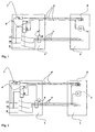
- the fire protection device with a circuit diagram according to FIG. 1 shows a power plug 1, which is connected to the dishwasher 2 via electrical conductor bundles 3 and 4.
- the conductor bundles 3 lead from the power plug 1 to the electrical loads such as motors or heating, the conductor bundles 4 lead from the power plug 1 to the main switch, which may be formed, for example as a rocker switch.
- the conductor bundles 4 are designed as low-voltage conductors.
- a gas sensor 5 is arranged in the embodiments shown, which is associated with a gas sensor circuit and electrical conductors connected to the main switch 6, so that when a signal of the gas sensor 5, the main switch 6 interrupts the main circuit and the dishwasher 2 de-energized is present.
- a transformer unit 7 which transforms the 230 V AC voltage flowing in via strands L1 to a low voltage.
- a relay 8 in the embodiments, a bistable relay 8, provided in the power plug 1, which is connected via the two channels R and S to the main switch 6. With the signal on channel S induced by the main switch 6, the relay 8 closes and switches on the dishwasher 2, and with the signal on channel R the relay 8 opens and switches off the dishwasher 2.
- a fire protection device for household appliances 2 which takes at the beginning of a malfunction with potential fire sequence of the dishwasher 2 measures to both protect the dishwasher 2 from further damage, as well as to prevent fire hazards.
Landscapes
- Health & Medical Sciences (AREA)
- Public Health (AREA)
- Business, Economics & Management (AREA)
- Emergency Management (AREA)
- Breakers (AREA)
- Fire Alarms (AREA)
- Details Of Connecting Devices For Male And Female Coupling (AREA)
- Fire-Extinguishing By Fire Departments, And Fire-Extinguishing Equipment And Control Thereof (AREA)
- Inorganic Insulating Materials (AREA)
- Buildings Adapted To Withstand Abnormal External Influences (AREA)
- Sink And Installation For Waste Water (AREA)
- Emergency Protection Circuit Devices (AREA)
Description
- Die Erfindung betrifft eine Brandschutzeinrichtung für Haushaltgeräte bestehend aus wenigstens einem Fehlerstromschutzschalter und wenigstens einem Gassensor mit Gassensorschaltung, wobei der wenigstens eine Fehlerstromschutzschalter so ausgebildet ist, dass ein Fehlerstrom in einem der elektrischen Leiter des Haushaltgeräts zu einem Abschalten der elektrischen Versorgung des Haushaltgeräts führt und der wenigstens eine Gassensor ab einer gewissen Menge eines Leitgases innerhalb des Haushaltgeräts ein Signal erzeugt, welches ebenfalls zu einem Abschalten der elektrischen Versorgung des Haushaltgeräts führt.
- Z. B. weist die selbständige bzw. autonome Brandschutzvorrichtung der
FR 2 543 839 - Haushaltgeräte, die mehrere Stromverbraucher, wie beispielsweise Motoren, Heizungen etc. aufweisen, unterliegen üblicherweise keiner individuellen Überprüfung ihrer elektrischen Sicherheit. Zur Vermeidung von Beschädigungen des Haushaltgerätes in Folge von Überspannung weisen Haushaltgeräte regelmäßig Sicherungseinrichtungen auf, die beispielsweise einen in Porzellan oder Keramik eingebrachten Sicherungsstift aufweisen, der bei Erreichen einer bestimmten Stromstärke durchglüht und so das Haushaltgerät vor weiterem Schaden bewahrt, insbesondere Schwelbrände oder dergleichen.
- Da bei der Herstellung von elektrischen Geräten für den Haushalt auch entzündbare und entflammbare Werkstoffe verwendet werden, kann ein erhöhtes Risiko bestehen, dass diese Werkstoffe bei einem Kurzschluss oder einem Verschleiß von elektrischen Leitern in Brand geraten. Zum Löschen so entstandener Brände ist aus der
DE 38 09 754 A1 eine Vorrichtung mit einem Behälter für einen Feuerlöschstoff bekannt, der sich in Anwesenheit einer Flamme oder beim Ansteigen der Umgebungstemperatur bis über einen Grenzwert hinaus selbsttätig öffnet, um den Feuerlöschstoff mittelbar oder unmittelbar auf die feuergefährdeten bzw. zu schützenden Partien des Gerätes auszugießen. Hierbei kann z.B. die Anordnung so getroffen sein, dass die Behälter, vorzugsweise mehrere, jeweils Feuerlöschstoff enthaltende Zellen besitzen, die zweckmäßigerweise im Bodenbereich Bohrungen besitzen, die von einer Schutzhülle oder einem z. B. membranartigen Häutchen abgeschlossen sind, die bzw. das bei einer vorbestimmten Temperatur zum Öffnen der Bohrungen zerstört wird und hierbei den Feuerlöschstoff austreten lässt. - Als nachteilig hat sich bei dieser Vorrichtung erwiesen, dass zwar die in der Nachbarschaft des elektrischen Gerätes befindlichen Gegenstände von einem Ausbreiten des Brandes geschützt werden, jedoch das elektrische Haushaltgerät vollständig zerstört oder zumindest so stark beschädigt wird, dass erhebliche Reparaturleistungen notwendig werden. Auch wenn sich, im Verhältnis zu einer Zerstörung mehrerer Haushaltgeräte, beispielsweise in der Küche, der Verlust eines einzelnen Haushaltgerätes als verhältnismäßig gering erweist, so ist es dennoch wünschenswert auch dieses elektrische Haushaltgerät, sofern möglich, vor einem Totalschaden zu bewahren. Da die Vorrichtung gemäß
DE 38 09 754 A1 jedoch erst bei einer bereits stattgefundenen Teilzerstörung der Elektrik Einsatz findet, ist bereits ein wesentlicher Schaden bei diesem elektrischen Gerät entstanden. - Das elektrische Feuerdetektions- und Feuervermeidungs/Feuerlöschsystem der
US 5,936,531 umfasst ein dichtes Gehäuse, in dem elektrische Schaltkreise, die an eine Energieversorgung angekoppelt sind, sowie ein Funkensensor, ein Hitzesensor und ein Rauchdetektor untergebracht sind, sowie eine Feuerlöscheinrichtung. Ferner umfasst das System einen Kontrolllogikschaltkreis, der an den Funkensensor, den Hitzesensor, den Rauchdetektor und die Feuerlöscheinrichtung angekoppelt ist. Wenn ein Funke vom Funkensensor detektiert wird, schaltet der Kontrolllogikschaltkreis die Energieversorgung ab. Wenn ein Hitzeanstieg vom Hitzsensor oder Rauch vom Rauchdetektor detektiert wird, schaltet der Kontrolllogikschaltkreis die Energieversorgung ab und aktiviert die Feuerlöscheinrichtung. - Aufgabe der vorliegenden Erfindung ist es daher, eine Brandschutzeinrichtung für Haushaltgeräte bereitzustellen, welche bereits zu Beginn einer Fehlfunktion mit potentieller Brandfolge des Haushaltgeräts Maßnahmen ergreift, um sowohl das Haushaltsgerät vor weiterem Schaden zu schützen, als auch einer Brandgefahr vorzubeugen.
- Erfindungsgemäß wird diese Aufgabe durch eine Brandschutzeinrichtung mit den Merkmalen gemäß Anspruch 1 gelöst. Vorteilhafte Ausgestaltungen der vorliegenden Erfindung sind in den Unteransprüchen gekennzeichnet.
- Mit der erfindungsgemäßen Brandschutzeinrichtung für Haushaltgeräte wird ein Ausbreiten von Schwelbränden, die von elektrischen Fehlern ausgehen, vermieden, da die bei einem Schwelbrand entstehenden Gase durch wenigstens einen Gassensor detektiert werden und ab einer gewissen Menge eines Leitgases, beispielsweise Kohlenmonoxyd (CO) und/oder Chlor (Cl) innerhalb des Haushaltgeräts ein Signal erzeugt wird, welches zu einem, vorzugsweise allpoligen, Abschalten der elektrischen Versorgung innerhalb des Haushaltgeräts führt. Neben dem Gassensor ist ferner wenigstens ein Fehlerstromschutzschalter angeordnet, der bereits bei einem Fehlerstrom bei einem der elektrischen Leiter des Haushaltgeräts ein, vorzugsweise allpoliges, Abschalten der elektrischen Versorgung des Haushaltgeräts einleitet und so beispielsweise ein Aufheizen und Entzünden von Kunststoffen verhindert. Erfindungsgemäß ist der Fehlerstromschutzschalter im Netzstecker des Haushaltgeräts integriert, so dass der Netzstecker lediglich eine etwas größere Abmessung als übliche Netzstecker aufweist, oder wenn der Fehlerstromschutzschalter so im Haushaltgerät angeordnet ist, dass er eine Funktion als Hauptschalter ausfüllt, d.h. das Haushaltgerät über den Fehlerstromschutzschalter an und ausgeschaltet werden kann. Durch diese kompakte Bauweise ist es möglich, die erfindungsgemäße Brandschutzeinrichtung in drei Hauptkomponenten aufzuteilen, bestehend aus einer speziellen Gassensortechnik im Bodenraum oder der Türe des Haushaltgeräts, einem besonderen Netzstecker, bzw. Hauptschalter und elektrische Leiter, die die zusätzliche Funktion der, vorzugsweise allpoligen, Abschaltung des Haushaltgeräts vornehmen.
- Mit der erfindungsgemäßen Brandschutzeinrichtung für Haushaltgeräte wird erreicht, dass ein Fehlerstrom, ein Schwelbrand, ein offener Brand oder Rauch erkannt wird und die Geschirrspülmaschine unverzüglich vom elektrischen Netz getrennt wird und somit einerseits ein Ausbreiten der Fehlfunktionen unterbunden bzw. ein Entstehen der Fehlfunktionen verhindert und andererseits die elektrische Zündenergie für den Brand oder Schwelbrand genommen wird. Bei Verwendung der erfindungsgemäßen Brandschutzeinrichtung für Haushaltgeräte werden Fehlerströme oder Kurzschlüsse im Gerät bereits erkannt, bevor es zum Ausbruch eines dadurch verursachten Schwelbrandes oder offenen Brandes kommen kann. Ferner werden durch den Gassensor Rauchentwicklungen, die im wesentlichen auf Polyethylen (PE), Polypropylen (PP), Polyamid (PA), Polyvinylchlorid (PVC) oder Polystyrol (PS) zurückzuführen sind, frühzeitig erkannt, da beim Verbrennen dieser Kunststoffe Kohlenmonoxyd (CO) und/oder Chlor (Cl) freigesetzt wird. Durch die Netzabschaltung wird ein Übergreifen von Kriechströmen von bzw. zu benachbarten elektrischen Geräten verhindert, die sich im selben Stromkreis befinden. Mit der Erfindung ist eine Brandschutzeinrichtung für Haushaltgeräte bereitgestellt, welche bereits zu Beginn einer Fehlfunktion mit potentieller Brandfolge des Haushaltgeräts Maßnahmen ergreift, um sowohl das Haushaltgerät vor weiterem Schaden zu schützen, als auch einer Brandgefahr vorzubeugen.
- Vorteilhafterweise wird der Hauptschalter des Haushaltgeräts, der zur Versorgung der einzelnen Baugruppen des Haushaltgeräts verwendet wird, mit dem Netzstecker verbunden, wobei der Hauptschalter lediglich mit Niederspannung gespeist wird. Mit der erfindungsgemäßen Brandschutzeinrichtung wird gewährleistet, dass wesentliche im Innenraum des Haushaltgeräts verlaufenden elektrischen Ströme als Niederspannung bereitgestellt werden, mit Ausnahme von elektrischen Strömen z.B. für Motoren und Heizungen. Durch die erfindungsgemäße Brandschutzeinrichtung wird vorteilhafterweise kein elektrischer Leiter mit Wechselstrom in Höhe von 230 V durch das Haushaltgerät bis zum Hauptschalter geführt.
- Vorteilhafterweise ist der Gassensor im Bodenbereich und/oder einer Tür des Haushaltgeräts angeordnet. Das Signal für das An-, Aus- bzw. Abschalten des Haushaltgeräts mittels Fehlerstromschutzschalter kann über direkte Verbindung (Leitung/Litze), als Funksignal oder auch über einen geräteinternen bzw. geräteexternen Bus erfolgen. Durch An-, Aus- bzw. Abschalten des Haushaltgeräts mittels Fehlerstromschutzschalter wird der Fehlerstromschutzschalter vorteilhafterweise jedes Mal auch in seiner Funktion überprüft. Die Gassensorschaltung vergleicht die hinterlegten Ist-Werte mit den detektierten Werten und löst bei entsprechender Abweichung ein Abschaltungssignal aus. Dieses Signal führt zur, vorzugsweise allpoligen, Abschaltung des Hausgerätes.
- Nachfolgend wird die erfindungsgemäße Brandschutzeinrichtung anhand bevorzugter Ausführungsformen näher erläutert. Es zeigen:
- Figur 1:
- einen Schaltplan eines Netzsteckers, dessen erfindungsgemäße Brand- schutzeinrichtung sowie eine schematische Darstellung des Haushaltge- räts;
- Figur 2:
- eine andere bevorzugte Ausführungsform der erfindungsgemäßen Brand- schutzeinrichtung.
- Im folgenden wird die erfindungsgemäße Brandschutzeinrichtung für Haushaltgeräte am Beispiel einer Geschirrspülmaschine 2 erläutert.
- Die erfindungsgemäße Brandschutzeinrichtung mit einem Schaltplan gemäß
Figur 1 zeigt einen Netzstecker 1, der mit der Geschirrspülmaschine 2 über elektrische Leiterbündel 3 und 4 verbunden ist. Die Leiterbündel 3 führen von dem Netzstecker 1 zu den elektrischen Verbrauchern wie beispielsweise Motoren oder Heizung, die Leiterbündel 4 führen von dem Netzstecker 1 zum Hauptschalter, der z.B. als Wipptaster ausgebildet sein kann. Die Leiterbündel 4 sind als Niederspannungsleiter ausgebildet. Im Bodenraum der Geschirrspülmaschine 2 ist in den gezeigten Ausführungsbeispielen ein Gassensor 5 angeordnet, dem eine Gassensorschaltung zugeordnet ist, und über elektrische Leiter mit dem Hauptschalter 6 verbunden, so dass bei einem Signal des Gassensors 5 der Hauptschalter 6 den Hauptstromkreis unterbricht und die Geschirrspülmaschine 2 stromlos vorliegt. Im Netzstecker 1 ist eine Transformatoreinheit 7 vorgesehen, die die über Litzen L1 einfließende 230 V Wechselspannung auf eine Niederspannung transformiert. Weiterhin ist ein Relais 8, in den Ausführungsbeispielen ein bistabiles Relais 8, in dem Netzstecker 1 vorgesehen, das über die beiden Kanäle R und S mit dem Hauptschalter 6 verbunden ist. Mit dem von dem Hauptschalter 6 induzierten Signal auf Kanal S schließt das Relais 8 und schaltet die Geschirrspülmaschine 2 an und mit dem Signal auf Kanal R öffnet das Relais 8 und schaltet die Geschirrspülmaschine 2 ab. Im Hauptstromkreis, der im wesentlichen über die Leiterbündel 3 aufgebaut wird, befindet sich ein Summenstromwandler 9, der stets die Summe aller Ströme misst und ab einer gewissen Abweichung, die beispielsweise auf einen Fehlerstrom zurückzuführen sind, ein Signal an den Rücksetzeingang - den Kanal R - des Relais 8 übermittelt, so dass schließlich der Hauptschalter 6 der Geschirrspülmaschine 2 allpolig abschaltet. - Bei der erfindungsgemäßen Brandschutzeinrichtung mit einem Schaltplan gemäß
Figur 2 sind die gleichen Baueinheiten wie beim Schaltplan gemäßFigur 1 vorgesehen. Eine technische Variante besteht lediglich darin, den Gassensor 5 und den Hauptschalter 6 nicht direkt in den Rücksetzkanal des Relais 8 zu führen sondern beide Leiter über den Schutzleiter PE zu führen. Die technischen Merkmale, insbesondere die Leistungsmerkmale der Schaltung gemäßFigur 2 , sind indes identisch mit den Leistungsmerkmalen der Schaltung gemäßFigur 1 . - Mit der Erfindung ist eine Brandschutzeinrichtung für Haushaltgeräte 2 bereitgestellt, welche bereits zu Beginn einer Fehlfunktion mit potentieller Brandfolge der Geschirrspülmaschine 2 Maßnahmen ergreift, um sowohl die Geschirrspülmaschine 2 vor weiterem Schaden zu schützen, als auch einer Brandgefahr vorzubeugen.
Claims (9)
- Brandschutzeinrichtung für Haushaltgeräte bestehend aus wenigstens einem Fehlerstromschutzschalter und wenigstens einem Gassensor (5) mit Gassensorschaltung, wobei der wenigstens eine Fehlerstromschutzschalter so ausgebildet ist, dass ein Fehlerstrom in einem der elektrischen Leiter des Haushaltgeräts (2) zu einem Abschalten der elektrischen Versorgung des Haushaltgeräts (2) führt und der wenigstens eine Gassensor (5) ab einer gewissen Menge eines Leitgases innerhalb des Haushaltgeräts (2) ein Signal erzeugt, welches ebenfalls zu einem Abschalten der elektrischen Versorgung des Haushaltgeräts . (2) führt, dadurch gekennzeichnet, dass der Fehlerstromschutzschalter im Netzstecker (1) des Haushaltgeräts (2) integriert ist.
- Brandschutzeinrichtung nach Anspruch 1, dadurch gekennzeichnet, dass ein Fehlerstrom in einem der elektrischen Leiter des Haushaltgeräts (2) zu einem allpoligen Abschalten der elektrischen Versorgung des Haushaltgeräts (2) führt und der wenigstens eine Gassensor (5) ab einer gewissen Menge eines Leitgases innerhalb des Haushaltgeräts (2) ein Signal erzeugt, welches ebenfalls zu einem allpoligen Abschalten der elektrischen Versorgung des Haushaltgeräts (2) führt.
- Brandschutzeinrichtung nach einem der Ansprüche 1 oder 2, dadurch gekennzeichnet, dass mit dem Netzstecker (1) ein Hauptschalter (6) zur Versorgung der einzelnen Baugruppen des Haushaltgeräts (2) verbunden ist, und dieser Hauptschalter (6) lediglich mit Niederspannung gespeist wird.
- Brandschutzeinrichtung nach Anspruch 3, dadurch gekennzeichnet, dass die Gassensorschaltung mit Gassensor (5) mit dem Fehlerstromschutzschalter verbunden ist.
- Brandschutzeinrichtung nach Anspruch 3, dadurch gekennzeichnet, dass die Gassensorschaltung mit Gassensor (5) direkt mit dem Schutzleiter (PE) verbunden ist und bei einer gewissen Konzentration des Leitgases der Fehlerstromschutzschalter ausgelöst wird.
- Brandschutzeinrichtung nach Anspruch 3, dadurch gekennzeichnet, dass der Hauptschalter (6) direkt mit dem Schutzleiter (PE) verbunden ist.
- Brandschutzeinrichtung nach einem der vorherigen Ansprüche, dadurch gekennzeichnet, dass der Fehlerstromschutzschalter als Hauptschalter für das Haushaltgerät (2) wirkt.
- Brandschutzeinrichtung nach einem der vorherigen Ansprüche, dadurch gekennzeichnet, dass der Gassensor (5) in einer Tür des Haushaltgeräts (2) angeordnet ist.
- Brandschutzeinrichtung nach einem der vorherigen Ansprüche, dadurch gekennzeichnet, dass der Gassensor (5) im Bodenbereich des Haushaltgeräts (2) angeordnet ist.
Applications Claiming Priority (3)
| Application Number | Priority Date | Filing Date | Title |
|---|---|---|---|
| DE10130608 | 2001-06-26 | ||
| DE10130608A DE10130608A1 (de) | 2001-06-26 | 2001-06-26 | Brandschutzeinrichtung für Haushaltgeräte |
| PCT/EP2002/006518 WO2003002208A1 (de) | 2001-06-26 | 2002-06-13 | Brandschutzeinrichtung für haushaltgeräte |
Publications (2)
| Publication Number | Publication Date |
|---|---|
| EP1404417A1 EP1404417A1 (de) | 2004-04-07 |
| EP1404417B1 true EP1404417B1 (de) | 2010-08-11 |
Family
ID=7689385
Family Applications (1)
| Application Number | Title | Priority Date | Filing Date |
|---|---|---|---|
| EP02760178A Expired - Lifetime EP1404417B1 (de) | 2001-06-26 | 2002-06-13 | Brandschutzeinrichtung für haushaltgeräte |
Country Status (6)
| Country | Link |
|---|---|
| US (2) | US20040140191A1 (de) |
| EP (1) | EP1404417B1 (de) |
| AT (1) | ATE477025T1 (de) |
| DE (2) | DE10130608A1 (de) |
| ES (1) | ES2348437T3 (de) |
| WO (1) | WO2003002208A1 (de) |
Families Citing this family (8)
| Publication number | Priority date | Publication date | Assignee | Title |
|---|---|---|---|---|
| US7597967B2 (en) | 2004-12-17 | 2009-10-06 | Eastman Kodak Company | Phosphorescent OLEDs with exciton blocking layer |
| ATE535895T1 (de) | 2006-10-09 | 2011-12-15 | Per Erik Lie | Brandschutzsystem für elektrische anlagen |
| DE102007058379A1 (de) * | 2007-12-05 | 2009-06-10 | BSH Bosch und Siemens Hausgeräte GmbH | Schaltungsanordnung zum Betreiben eines Hausgeräts |
| DE102010012311A1 (de) * | 2010-03-23 | 2011-09-29 | Diehl Ako Stiftung & Co. Kg | Steuerschaltung für ein elektronisches Haushaltsgerät |
| FI126189B (fi) * | 2015-09-21 | 2016-08-15 | Innohome Oy | Valvonta- ja ohjausmenetelmä huonon ilmanlaadun ja tulipalon ehkäisemiseksi sekä vaarallisen tilan hälyttämiseksi |
| US20170263095A1 (en) * | 2016-03-11 | 2017-09-14 | Percival A. Peck | Appliances Built-in Safety Features |
| US11177102B2 (en) * | 2017-05-05 | 2021-11-16 | Astronics Advanced Electronic Systems Corp. | Volatile organic compound controlled relay for power applications |
| CN110314313B (zh) * | 2019-05-14 | 2021-03-02 | 江苏亨诺科技有限公司 | 一种智能家居消防系统 |
Citations (1)
| Publication number | Priority date | Publication date | Assignee | Title |
|---|---|---|---|---|
| US5936531A (en) * | 1998-03-06 | 1999-08-10 | Powers; Frank A. | Electrical fire sensing and prevention/extinguishing system |
Family Cites Families (18)
| Publication number | Priority date | Publication date | Assignee | Title |
|---|---|---|---|---|
| US1979976A (en) * | 1932-05-12 | 1934-11-06 | Gen Electric | Gas detector |
| US3824374A (en) * | 1971-05-13 | 1974-07-16 | E Mayher | Condition responsive disconnect arrangement for electrical cooking equipment |
| SE369636B (de) * | 1973-11-28 | 1974-09-09 | Ericsson Telefon Ab L M | |
| US4436972A (en) * | 1980-09-03 | 1984-03-13 | Heinemann Electric Company | Circuit protector having a lamp within its handle and terminals therefor |
| FR2543839B1 (fr) * | 1983-04-08 | 1986-04-18 | Pgep | Dispositif autonome de protection d'un ensemble electrique contre l'incendie |
| US4483314A (en) * | 1983-06-09 | 1984-11-20 | James A. Hackney, III | Cooking range with fire extinguishing facility |
| US4484185A (en) * | 1983-08-12 | 1984-11-20 | Graves James D | Safety plug adapter |
| US4834188A (en) * | 1987-03-19 | 1989-05-30 | Twenty-First Century International Fire Equipment And Services Corp. | Fire extinguishing system for cookstoves and ranges |
| US4751401A (en) * | 1987-03-23 | 1988-06-14 | Core Industries Inc. | Low voltage switch |
| ES2006865A6 (es) | 1987-04-24 | 1989-05-16 | Faini Spa | Dispositivo de proteccion contra el incendio de aparatos electricos con partes inflamables. |
| US5039006A (en) * | 1989-08-16 | 1991-08-13 | Habegger Millard A | Home heating system draft controller |
| NZ236551A (en) * | 1990-12-19 | 1995-07-26 | Fisher & Paykel | Direct current power supply energised from current commutated through motor winding |
| US5453725A (en) * | 1994-05-25 | 1995-09-26 | You; Long-Cheng | Overcurrent breaker switch |
| US5844759A (en) * | 1995-05-26 | 1998-12-01 | David C. Nemir | Electrical fault interrupter |
| US5943199A (en) * | 1997-04-22 | 1999-08-24 | Tower Manufacturing Corporation | Mini appliance leakage current interrupter |
| US6046441A (en) * | 1998-05-05 | 2000-04-04 | Daffron; Thomas Robert | Combustion activated device for disabling an electrical appliance |
| US5946180A (en) * | 1998-08-26 | 1999-08-31 | Ofi Inc. | Electrical connection safety apparatus and method |
| US6603221B1 (en) * | 1999-04-22 | 2003-08-05 | Zhongdu Liu | Solid state electrical switch |
-
2001
- 2001-06-26 DE DE10130608A patent/DE10130608A1/de not_active Withdrawn
-
2002
- 2002-06-13 WO PCT/EP2002/006518 patent/WO2003002208A1/de not_active Ceased
- 2002-06-13 DE DE50214580T patent/DE50214580D1/de not_active Expired - Lifetime
- 2002-06-13 ES ES02760178T patent/ES2348437T3/es not_active Expired - Lifetime
- 2002-06-13 AT AT02760178T patent/ATE477025T1/de active
- 2002-06-13 EP EP02760178A patent/EP1404417B1/de not_active Expired - Lifetime
-
2003
- 2003-12-10 US US10/734,054 patent/US20040140191A1/en not_active Abandoned
-
2010
- 2010-03-11 US US12/721,590 patent/US8958191B2/en not_active Expired - Fee Related
Patent Citations (1)
| Publication number | Priority date | Publication date | Assignee | Title |
|---|---|---|---|---|
| US5936531A (en) * | 1998-03-06 | 1999-08-10 | Powers; Frank A. | Electrical fire sensing and prevention/extinguishing system |
Also Published As
| Publication number | Publication date |
|---|---|
| DE50214580D1 (de) | 2010-09-23 |
| EP1404417A1 (de) | 2004-04-07 |
| ES2348437T3 (es) | 2010-12-07 |
| ATE477025T1 (de) | 2010-08-15 |
| US8958191B2 (en) | 2015-02-17 |
| DE10130608A1 (de) | 2003-01-09 |
| US20100165531A1 (en) | 2010-07-01 |
| US20040140191A1 (en) | 2004-07-22 |
| WO2003002208A1 (de) | 2003-01-09 |
Similar Documents
| Publication | Publication Date | Title |
|---|---|---|
| DE69516074T2 (de) | Steckdoseneinheit und Verlängerungsschnur | |
| EP1404417B1 (de) | Brandschutzeinrichtung für haushaltgeräte | |
| EP1404416B1 (de) | Brandschutz- und brandlöscheinrichtung für wasserführende haushaltgeräte | |
| DE102011001340A1 (de) | Elektrische Vorrichtung für den Kurzschlussschutz einer Drehstromlast in einem Drehstromsystem | |
| WO2018104440A2 (de) | Schaltschrank | |
| EP1884902B1 (de) | Verfahren und einrichtung zum verhindern von durch defekte in elektrischen schaltungen und anordnungen verursachtem feuer | |
| EP0061652A1 (de) | Überspannungsschutzvorrichtung für elektrische Hausinstallationsanlagen | |
| CN204596224U (zh) | 一种电气火灾模拟示验箱 | |
| EP0268107B1 (de) | Schutzvorrichtung gegen Gasexplosionen in Wohnräumen | |
| DE102011001734A1 (de) | Überspannungsschutzeinrichtung | |
| EP0848471B1 (de) | Fehlerstromschutzeinrichtung | |
| EP3552287A1 (de) | Verfahren zur abschaltung eines lichtbogens in einer elektrischen anlage | |
| DE3336697C2 (de) | ||
| CN206524484U (zh) | 一种电源侧地线失效时能自动断电并音响报警的安全插座 | |
| DE3539421A1 (de) | Schaltungsanordnung zum schutz gegen ueberspannungen | |
| DE20105656U1 (de) | Sicherheitsvorrichtung für elektrisch angetriebene Pflege- und Krankenbetten | |
| DE202014006362U1 (de) | Anordnung zur Erfassung von Störlichtbögen in einem Niederspannungsnetz | |
| DE102020000289B4 (de) | Elektrisches System zur Erhöhung des Schutzes gegen elektrischen Stromschlag durch neue Sicherheitsanschlußleitungen | |
| DE102014005774B4 (de) | Brandschutzadaptervorrichtung | |
| EP1361636A1 (de) | Schutzschalter für eine Kabeltrommel | |
| Leonard et al. | Electrical hazards in the home: What do people know? | |
| DE3306384A1 (de) | Geraet zur ueberwachung der temperatur von elektrisch betriebenen geraeten | |
| Calvas et al. | System earthing in LV | |
| AT412830B (de) | Hauptschaltgerät für den brandschutz in genullten verbraucheranlagen mit netzspannungsabhängiger fehlerstromauslösung und hohem selektivitätsverhalten (nullungsschutzschalter) | |
| Madden | Electrical Safety and the Law |
Legal Events
| Date | Code | Title | Description |
|---|---|---|---|
| PUAI | Public reference made under article 153(3) epc to a published international application that has entered the european phase |
Free format text: ORIGINAL CODE: 0009012 |
|
| 17P | Request for examination filed |
Effective date: 20040126 |
|
| AK | Designated contracting states |
Kind code of ref document: A1 Designated state(s): AT BE CH CY DE DK ES FI FR GB GR IE IT LI LU MC NL PT SE TR |
|
| RAP1 | Party data changed (applicant data changed or rights of an application transferred) |
Owner name: BSH BOSCH UND SIEMENS HAUSGERAETE GMBH |
|
| 17Q | First examination report despatched |
Effective date: 20090805 |
|
| GRAP | Despatch of communication of intention to grant a patent |
Free format text: ORIGINAL CODE: EPIDOSNIGR1 |
|
| GRAS | Grant fee paid |
Free format text: ORIGINAL CODE: EPIDOSNIGR3 |
|
| GRAA | (expected) grant |
Free format text: ORIGINAL CODE: 0009210 |
|
| AK | Designated contracting states |
Kind code of ref document: B1 Designated state(s): AT BE CH CY DE DK ES FI FR GB GR IE IT LI LU MC NL PT SE TR |
|
| REG | Reference to a national code |
Ref country code: GB Ref legal event code: FG4D Free format text: NOT ENGLISH |
|
| REG | Reference to a national code |
Ref country code: CH Ref legal event code: EP |
|
| REG | Reference to a national code |
Ref country code: IE Ref legal event code: FG4D Free format text: LANGUAGE OF EP DOCUMENT: GERMAN |
|
| REF | Corresponds to: |
Ref document number: 50214580 Country of ref document: DE Date of ref document: 20100923 Kind code of ref document: P |
|
| REG | Reference to a national code |
Ref country code: ES Ref legal event code: FG2A Effective date: 20101124 |
|
| REG | Reference to a national code |
Ref country code: NL Ref legal event code: VDEP Effective date: 20100811 |
|
| PG25 | Lapsed in a contracting state [announced via postgrant information from national office to epo] |
Ref country code: FI Free format text: LAPSE BECAUSE OF FAILURE TO SUBMIT A TRANSLATION OF THE DESCRIPTION OR TO PAY THE FEE WITHIN THE PRESCRIBED TIME-LIMIT Effective date: 20100811 Ref country code: NL Free format text: LAPSE BECAUSE OF FAILURE TO SUBMIT A TRANSLATION OF THE DESCRIPTION OR TO PAY THE FEE WITHIN THE PRESCRIBED TIME-LIMIT Effective date: 20100811 |
|
| PG25 | Lapsed in a contracting state [announced via postgrant information from national office to epo] |
Ref country code: PT Free format text: LAPSE BECAUSE OF FAILURE TO SUBMIT A TRANSLATION OF THE DESCRIPTION OR TO PAY THE FEE WITHIN THE PRESCRIBED TIME-LIMIT Effective date: 20101213 Ref country code: CY Free format text: LAPSE BECAUSE OF FAILURE TO SUBMIT A TRANSLATION OF THE DESCRIPTION OR TO PAY THE FEE WITHIN THE PRESCRIBED TIME-LIMIT Effective date: 20100811 |
|
| REG | Reference to a national code |
Ref country code: IE Ref legal event code: FD4D |
|
| PG25 | Lapsed in a contracting state [announced via postgrant information from national office to epo] |
Ref country code: SE Free format text: LAPSE BECAUSE OF FAILURE TO SUBMIT A TRANSLATION OF THE DESCRIPTION OR TO PAY THE FEE WITHIN THE PRESCRIBED TIME-LIMIT Effective date: 20100811 Ref country code: GR Free format text: LAPSE BECAUSE OF FAILURE TO SUBMIT A TRANSLATION OF THE DESCRIPTION OR TO PAY THE FEE WITHIN THE PRESCRIBED TIME-LIMIT Effective date: 20101112 |
|
| PG25 | Lapsed in a contracting state [announced via postgrant information from national office to epo] |
Ref country code: IE Free format text: LAPSE BECAUSE OF FAILURE TO SUBMIT A TRANSLATION OF THE DESCRIPTION OR TO PAY THE FEE WITHIN THE PRESCRIBED TIME-LIMIT Effective date: 20100811 Ref country code: DK Free format text: LAPSE BECAUSE OF FAILURE TO SUBMIT A TRANSLATION OF THE DESCRIPTION OR TO PAY THE FEE WITHIN THE PRESCRIBED TIME-LIMIT Effective date: 20100811 |
|
| PLBE | No opposition filed within time limit |
Free format text: ORIGINAL CODE: 0009261 |
|
| STAA | Information on the status of an ep patent application or granted ep patent |
Free format text: STATUS: NO OPPOSITION FILED WITHIN TIME LIMIT |
|
| 26N | No opposition filed |
Effective date: 20110512 |
|
| REG | Reference to a national code |
Ref country code: DE Ref legal event code: R097 Ref document number: 50214580 Country of ref document: DE Effective date: 20110512 |
|
| BERE | Be: lapsed |
Owner name: BSH BOSCH UND SIEMENS HAUSGERATE G.M.B.H. Effective date: 20110630 |
|
| REG | Reference to a national code |
Ref country code: CH Ref legal event code: PL |
|
| PG25 | Lapsed in a contracting state [announced via postgrant information from national office to epo] |
Ref country code: BE Free format text: LAPSE BECAUSE OF NON-PAYMENT OF DUE FEES Effective date: 20110630 |
|
| PG25 | Lapsed in a contracting state [announced via postgrant information from national office to epo] |
Ref country code: CH Free format text: LAPSE BECAUSE OF NON-PAYMENT OF DUE FEES Effective date: 20110630 Ref country code: LI Free format text: LAPSE BECAUSE OF NON-PAYMENT OF DUE FEES Effective date: 20110630 |
|
| REG | Reference to a national code |
Ref country code: AT Ref legal event code: MM01 Ref document number: 477025 Country of ref document: AT Kind code of ref document: T Effective date: 20110613 |
|
| PG25 | Lapsed in a contracting state [announced via postgrant information from national office to epo] |
Ref country code: AT Free format text: LAPSE BECAUSE OF NON-PAYMENT OF DUE FEES Effective date: 20110613 |
|
| PG25 | Lapsed in a contracting state [announced via postgrant information from national office to epo] |
Ref country code: MC Free format text: LAPSE BECAUSE OF NON-PAYMENT OF DUE FEES Effective date: 20110630 |
|
| PG25 | Lapsed in a contracting state [announced via postgrant information from national office to epo] |
Ref country code: LU Free format text: LAPSE BECAUSE OF NON-PAYMENT OF DUE FEES Effective date: 20110613 |
|
| PGFP | Annual fee paid to national office [announced via postgrant information from national office to epo] |
Ref country code: GB Payment date: 20140620 Year of fee payment: 13 |
|
| PGFP | Annual fee paid to national office [announced via postgrant information from national office to epo] |
Ref country code: TR Payment date: 20140610 Year of fee payment: 13 Ref country code: IT Payment date: 20140625 Year of fee payment: 13 Ref country code: ES Payment date: 20140618 Year of fee payment: 13 |
|
| PGFP | Annual fee paid to national office [announced via postgrant information from national office to epo] |
Ref country code: FR Payment date: 20140617 Year of fee payment: 13 |
|
| REG | Reference to a national code |
Ref country code: DE Ref legal event code: R081 Ref document number: 50214580 Country of ref document: DE Owner name: BSH HAUSGERAETE GMBH, DE Free format text: FORMER OWNER: BSH BOSCH UND SIEMENS HAUSGERAETE GMBH, 81739 MUENCHEN, DE Effective date: 20150407 |
|
| PG25 | Lapsed in a contracting state [announced via postgrant information from national office to epo] |
Ref country code: IT Free format text: LAPSE BECAUSE OF NON-PAYMENT OF DUE FEES Effective date: 20150613 |
|
| GBPC | Gb: european patent ceased through non-payment of renewal fee |
Effective date: 20150613 |
|
| REG | Reference to a national code |
Ref country code: FR Ref legal event code: ST Effective date: 20160229 |
|
| PG25 | Lapsed in a contracting state [announced via postgrant information from national office to epo] |
Ref country code: GB Free format text: LAPSE BECAUSE OF NON-PAYMENT OF DUE FEES Effective date: 20150613 |
|
| PG25 | Lapsed in a contracting state [announced via postgrant information from national office to epo] |
Ref country code: FR Free format text: LAPSE BECAUSE OF NON-PAYMENT OF DUE FEES Effective date: 20150630 |
|
| REG | Reference to a national code |
Ref country code: ES Ref legal event code: FD2A Effective date: 20160727 |
|
| PG25 | Lapsed in a contracting state [announced via postgrant information from national office to epo] |
Ref country code: ES Free format text: LAPSE BECAUSE OF NON-PAYMENT OF DUE FEES Effective date: 20150614 |
|
| PG25 | Lapsed in a contracting state [announced via postgrant information from national office to epo] |
Ref country code: TR Free format text: LAPSE BECAUSE OF NON-PAYMENT OF DUE FEES Effective date: 20150613 |
|
| PGFP | Annual fee paid to national office [announced via postgrant information from national office to epo] |
Ref country code: DE Payment date: 20190630 Year of fee payment: 18 |
|
| REG | Reference to a national code |
Ref country code: DE Ref legal event code: R119 Ref document number: 50214580 Country of ref document: DE |
|
| PG25 | Lapsed in a contracting state [announced via postgrant information from national office to epo] |
Ref country code: DE Free format text: LAPSE BECAUSE OF NON-PAYMENT OF DUE FEES Effective date: 20210101 |