EP1404946B1 - Moteur thermique en etoile avec piston flottant equilibre - Google Patents
Moteur thermique en etoile avec piston flottant equilibre Download PDFInfo
- Publication number
- EP1404946B1 EP1404946B1 EP02761037A EP02761037A EP1404946B1 EP 1404946 B1 EP1404946 B1 EP 1404946B1 EP 02761037 A EP02761037 A EP 02761037A EP 02761037 A EP02761037 A EP 02761037A EP 1404946 B1 EP1404946 B1 EP 1404946B1
- Authority
- EP
- European Patent Office
- Prior art keywords
- piston
- flywheel
- internal combustion
- engine
- eccentric gear
- Prior art date
- Legal status (The legal status is an assumption and is not a legal conclusion. Google has not performed a legal analysis and makes no representation as to the accuracy of the status listed.)
- Expired - Lifetime
Links
- 238000002485 combustion reaction Methods 0.000 title claims description 61
- 238000012546 transfer Methods 0.000 claims abstract description 21
- 239000000446 fuel Substances 0.000 claims description 15
- 239000000203 mixture Substances 0.000 claims description 6
- 239000012530 fluid Substances 0.000 claims description 5
- 238000004891 communication Methods 0.000 claims description 4
- 238000013461 design Methods 0.000 abstract description 25
- 238000010304 firing Methods 0.000 abstract description 5
- 230000008901 benefit Effects 0.000 description 8
- 230000006835 compression Effects 0.000 description 2
- 238000007906 compression Methods 0.000 description 2
- 238000010276 construction Methods 0.000 description 2
- 239000000463 material Substances 0.000 description 2
- 238000000034 method Methods 0.000 description 2
- XLYOFNOQVPJJNP-UHFFFAOYSA-N water Substances O XLYOFNOQVPJJNP-UHFFFAOYSA-N 0.000 description 2
- 230000005540 biological transmission Effects 0.000 description 1
- 238000001816 cooling Methods 0.000 description 1
- 238000003754 machining Methods 0.000 description 1
- 239000002184 metal Substances 0.000 description 1
- 238000011160 research Methods 0.000 description 1
- 238000010561 standard procedure Methods 0.000 description 1
Images


Classifications
-
- F—MECHANICAL ENGINEERING; LIGHTING; HEATING; WEAPONS; BLASTING
- F02—COMBUSTION ENGINES; HOT-GAS OR COMBUSTION-PRODUCT ENGINE PLANTS
- F02B—INTERNAL-COMBUSTION PISTON ENGINES; COMBUSTION ENGINES IN GENERAL
- F02B75/00—Other engines
- F02B75/16—Engines characterised by number of cylinders, e.g. single-cylinder engines
- F02B75/18—Multi-cylinder engines
- F02B75/22—Multi-cylinder engines with cylinders in V, fan, or star arrangement
- F02B75/222—Multi-cylinder engines with cylinders in V, fan, or star arrangement with cylinders in star arrangement
-
- F—MECHANICAL ENGINEERING; LIGHTING; HEATING; WEAPONS; BLASTING
- F02—COMBUSTION ENGINES; HOT-GAS OR COMBUSTION-PRODUCT ENGINE PLANTS
- F02B—INTERNAL-COMBUSTION PISTON ENGINES; COMBUSTION ENGINES IN GENERAL
- F02B53/00—Internal-combustion aspects of rotary-piston or oscillating-piston engines
- F02B53/02—Methods of operating
-
- F—MECHANICAL ENGINEERING; LIGHTING; HEATING; WEAPONS; BLASTING
- F02—COMBUSTION ENGINES; HOT-GAS OR COMBUSTION-PRODUCT ENGINE PLANTS
- F02B—INTERNAL-COMBUSTION PISTON ENGINES; COMBUSTION ENGINES IN GENERAL
- F02B2275/00—Other engines, components or details, not provided for in other groups of this subclass
- F02B2275/18—DOHC [Double overhead camshaft]
-
- Y—GENERAL TAGGING OF NEW TECHNOLOGICAL DEVELOPMENTS; GENERAL TAGGING OF CROSS-SECTIONAL TECHNOLOGIES SPANNING OVER SEVERAL SECTIONS OF THE IPC; TECHNICAL SUBJECTS COVERED BY FORMER USPC CROSS-REFERENCE ART COLLECTIONS [XRACs] AND DIGESTS
- Y02—TECHNOLOGIES OR APPLICATIONS FOR MITIGATION OR ADAPTATION AGAINST CLIMATE CHANGE
- Y02T—CLIMATE CHANGE MITIGATION TECHNOLOGIES RELATED TO TRANSPORTATION
- Y02T10/00—Road transport of goods or passengers
- Y02T10/10—Internal combustion engine [ICE] based vehicles
- Y02T10/12—Improving ICE efficiencies
Definitions
- This invention relates to a radial internal combustion engine.
- Radial engines are well known, and many attempts have been made to improve their ability to transfer the power of the exploding gas into mechanical power.
- the two major types of radial engines are the piston and the rotary engines. Although most radial engines are used for aircraft, many designs can be used in any application.
- U.S. Patent No. 4,084,555 describes a slosh plate type design that is used to transfer engine power to the power take-off.
- this design does not offer high torque and places all of the power transfer to one small location on the plate.
- the engine in U.S. Patent No. 4,194,404 uses a connecting rod for energy transfer but still places undo force on the piston and cylinder walls.
- the engine in U.S. Patent No. 4,727,794 does reduce the piston friction, but a larger engine block and an offset to the piston rods are used which can increase vibration.
- the engine in U.S. Patent No. 3,964,450 does reduce the friction by locking in the piston rod with thrust bearings.
- the engine includes an engine block having a plurality of combustion chambers radially arranged on the periphery of the engine block. Each combustion chamber is defined by a cylinder, a reciprocating piston contained within the cylinder, and a cylinder head on the periphery of the engine block.
- An exhaust port is associated with and in fluid communication with each combustion chamber. Each exhaust port includes an exhaust valve.
- An intake port is associated with and in fluid communication with each combustion chamber for directing intake air into its associated combustion chamber.
- Each intake port includes an intake valve.
- a fuel injector is associated with each intake port and its associated combustion chamber.
- Each fuel injector is positioned for directing fuel into intake air in its associated intake port or positioned for directing fuel into intake air in its associated combustion chamber to form an air-fuel mixture.
- a spark device is associated with each combustion chamber for igniting the air-fuel mixture in its associated combustion chamber.
- the engine includes an output shaft, and at least one flywheel secured to the output shaft.
- At least one system of arm and eccentric gear is connected to each piston, and at least one eccentric gear for each piston engages a surface of at least one flywheel. The reciprocating motion of each piston causes rotation of each eccentric gear that engages a surface of at least one flywheel thereby causing rotation of at least one flywheel and the output shaft.
- the radial engine of the present invention eliminates the need for both and allows for a piston to be supported by four gear wheels that distribute the power to two flywheels that connect all clockwise eccentric gears. This allows the piston at all times to run parallel to the cylinder wall with little resistance.
- the radial engine of the present invention can be made in any size diameter and can be paralleled with more of the same units.
- the engine can be made with any number of cylinders.
- the radial engine of the present invention uses a chain drive.
- One preferred design for the radial engine of the present invention has eight or more cylinders of even numbers and fires the cylinders 180 degrees to each other in unison. This allows the flywheel to pick up the power evenly from four gear wheels.
- the piston and block components are important features of the radial engine of the present invention.
- the piston is a very light low mass unit where the power, rather then going to a piston rod, goes to two flanges that can be permanent parts of the piston.
- the flanges bend out and turn 180 degrees to put the power takeoff outside of the engine block.
- This design can take many forms, such as multiple parts doing the same function and having a single piston stem that comes from the center of the piston that has a flange assembly alike to the above mentioned.
- the flange on the piston can be any size robust enough to handle the power delivery.
- the gear wheels can also be made larger or smaller to accommodate the size and compression requirements of the piston.
- the header on top of the cylinder of the radial engine of the present invention can be of a traditional design. If one wanted to add a standard valve construction it could be accomplished by placing a sinusoidal design to the outside of the flywheel so that the valve lever arm would ride on this curvature producing the required up and down motion needed for the valve actuation.
- designs incorporating electronic valves can eliminate camshaft, rods and chains.
- the entire engine block is housed in a two part container that can hold oil. Both sides of the container can hold oil or other fluids.
- This container can have the mounting brackets necessary to hold the engine in place in a vehicle or plane. Standard methods can pump the oil to the cylinders and to the cam and respective bearings. Water can pass around each cylinder as in conventional engines, and water lines can come out the outside diameter surface of the engine block. Air cooling is also suitable. Intake and exhaust manifolds are used wherein two cylinders share an intake and the next two cylinders share an outtake (exhaust). Gas is piped below the engine, outside the flywheel and main engine housing. Any number of cylinders is possible. Single cylinders and two cylinder designs with chain power take-offs are also possible for lawnmowers and motorcycles.
- the radial engine of the present invention eliminates a number of problems with all earlier engines and is easy to build with its parts simple to fabricate.
- the engine block would require less metal then a conventional engine block and is easy to mold or extrude. Since there is no crankshaft, its weight and machining are eliminated. Because of its flat design, the radial engine of the present invention can also offer a lower profile in modem cars lowering the hood and making it safer especially for accidents involving pedestrians.
- This chain has a center pickup shaft below the piston(s) where the chain would go over the counter clockwise rotation cams and positioned over two freewheeling sprockets that transfer the power to the main shaft.
- Figure 1 is a perspective view of one side of the engine block and selected components of a radial internal combustion engine according to the invention. A perspective view of the other side of the engine block is identical.
- Figure 2 is a top view of a piston of an engine according to the invention engaging the flywheel.
- Figure 3 is a side view of a piston of an engine according to the invention.
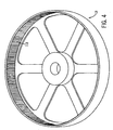
- Figure 4 is a perspective of a fly wheel of an engine according to the invention.
- a motor or pump 100 has an engine block 1 with cavities 20 designed to allow pistons 2 to fit in that cavity and assemble up into the cylinders 50.
- An eight cylinder configuration is shown.
- the pistons 2 have a flange 21 that is either an integral part of the piston or is bolted, welded or by some other means attached to the piston 2 to produce the same flange design.
- the flange 21 protrudes from both faces of the engine block 1 (the other side of the engine block having an identical view).
- the flange 21 may be narrower than the configuration shown to allow for assembly into the cylinder cavity.
- the piston flanges 21 are connected to four (two on each side) arms 3 that connect to gears 4 and 5.
- the arms 3 are connected with either simple rods 23, or with more elaborate bearings to the gears 4 and 5.
- These gears 4 and 5 are mounted in the engine block with center radial cam pins 22 that fit in bearings or sleeves.
- a cover plate is used to locate the top of the gear pins 22. There is one plate with two gear pins 22 for each of the eight gear pairs. This cover plate can connect to the engine block 1 with screws, bolts or other fasteners.
- the gear 4 to the left in all cases is the transfer gear and it allows for the power to transfer to the flywheel 13 by meshing with teeth 113 on an inner surface of the flywheel 13.
- the right hand gear 5 engages with the left hand gear 4 but typically does not engage with the flywheel 13. If transfer is necessary for a very high torque motor, a third gear can be placed between the gear 5 and the flywheel 13 to allow for proper rotational engagement.
- the right hand gear 5 can be designed to be smaller (with the same amount of teeth) or be offset so that it engages with the left hand gear 5 but not the flywheel 13. Also, the right hand gear 5 can be designed to engage the flywheel 13 with the addition of an extra gear.
- Another method for the transfer of power to the flywheel 13 is to have both gears 4 and 5 the same size but only the left gear 4 have teeth on both gear wheel surfaces.
- Gear 5 would have only one set of teeth and the flywheel 13 would in turn have teeth to engage only with the teeth in gear 4 that did not engage with gear 5.
- a second set of gears could be used to make the transfer by making the radius of the engine block larger.
- each gear pair is secured with a plate to the engine block 1
- the center main bearing 6 is inserted to finish the block assembly.
- a thrust bearing may be placed on top surface 25 of this central bearing 6 to support the flywheel 13.
- each of two flywheels 13 are placed over the all of the gears 4 and 5 in the engine 100. Teeth on each of the left gears 4 engage teeth 113 of the flywheel 13.
- An output shaft is then placed though the two flywheels 13 and central bearing 6, keyed into position and closed off with a housing (not shown) that covers the flywheel 13 and connects to the face of the engine block 1.
- cylinder heads 7 are placed on top of each cylinder opening and bolted into place.
- a standard fuel injectors 11, spark plugs or glow plugs 10, along with intake 8 and exhaust valves 9 are used in the engine.
- the valves are electrically actuated valves, are assembled to the cylinder heads 7.
- Intake manifolds and ports 12 and exhaust manifolds and ports 15 (both shown partially) connect two adjacent cylinder heads. The entrance/exits ports of these manifolds for the intake and for the exhaust would be piped to their respective manifolds.
- the engine 100 would function where 180 degree pistons would reach compression and fire followed by the their counterpart at 90 degrees to them.
- the other 4 cylinders would act in the same manner. This would, however, be just one possible firing sequence. It is advantageous to have opposing cylinders having the same firing timing to have a balanced system.
- the operation of internal combustion engines is well known and will not be explained further.
- the invention provides an improved radial internal combustion engine. Power is transferred from the engine such that the power take-off is truly balanced, where the piston runs truly parallel to the cylinder walls. This concept reduces wear of the cylinders and piston rings.
- the engine provides improved gas mileage due to the reduced piston drag.
- One unique feature is the power take-off from the piston to the flywheels. The design takes power from inside the cylinder compartment, through four transfer arms, to gears that in turn transfer the power to two flywheels. By firing complimentary cylinders 180 degrees at the same time, almost no vibration is noticed. Also, since the cylinders can fire many times per flywheel rotation, the torque which this engine produces is greater other designs. In the present invention, there is no need for counterweights or transmission gearing.
- This invention relates to a radial internal combustion engine that can be used to power automobiles, airplanes and the like.
Landscapes
- Engineering & Computer Science (AREA)
- Chemical & Material Sciences (AREA)
- Combustion & Propulsion (AREA)
- Mechanical Engineering (AREA)
- General Engineering & Computer Science (AREA)
- Shafts, Cranks, Connecting Bars, And Related Bearings (AREA)
- Valve-Gear Or Valve Arrangements (AREA)
- Transmission Devices (AREA)
- Lubrication Of Internal Combustion Engines (AREA)
Claims (23)
- Moteur à combustion interne radial comprenant :un bloc moteur (1) ayant une pluralité de chambres de combustion disposées de manière radiale sur la périphérie du bloc moteur, chaque chambre de combustion étant définie par un cylindre (50), un piston en va-et-vient (2) contenu dans le cylindre, et une tête de cylindre (7) sur la périphérie du bloc moteur ;un orifice d'échappement (15) associé à et en communication fluidique avec chaque chambre de combustion, chaque orifice d'échappement comprenant une soupape d'échappement (9) ;un orifice d'admission (12) associé à et en communication fluidique avec chaque chambre de combustion pour diriger l'air d'admission dans sa chambre de combustion associée, chaque orifice d'admission comprenant une soupape d'admission (8) ;un injecteur de combustible (11) associé à chaque orifice d'admission et à sa chambre de combustion associée, chaque injecteur de combustible étant positionné pour diriger le combustible dans l'air d'admission dans son orifice d'admission associé ou étant positionné pour diriger le combustible dans l'air d'admission dans sa chambre de combustion associée pour former un mélange air - combustible ;un dispositif d'allumage (10) associé à chaque chambre de combustion, pour allumer le mélange air - combustible dans sa chambre de combustion associée ;un arbre de sortie ;au moins une roue volante (13) fixé à l'arbre de sortie ; etau moins un système de bras (3) et d'engrenage excentrique (4, 5) connecté à chaque piston (2), au moins un engrenage excentrique (4, 5) pour chaque piston étant en prise avec une surface d'au moins une roue volante (13) de sorte que le mouvement en va-et-vient de chaque piston entraíne une rotation de chaque engrenage excentrique (4, 5) venant en prise avec une surface d'au moins une roue volante entraínant ainsi la rotation d'au moins une roue volante.
- Moteur à combustion interne radial selon la revendication 1, dans lequel chaque engrenage excentrique rotatif (4, 5) pour chaque piston (2) est connecté au piston par un bras (3).
- Moteur à combustion interne radial selon la revendication 2, dans lequel chaque bras (3) est connecté à une extrémité de chaque piston (2) opposée à la tête de cylindre (7) qui définit en partie la chambre de combustion pour chaque piston.
- Moteur à combustion interne radial selon la revendication 3, dans lequel chaque bras (3) est connecté à chaque piston (2) par une bride (21).
- Moteur à combustion interne radial selon la revendication 1, dans lequel au moins deux systèmes d'engrenage excentriques (4, 5) et de bras (3) sont connectés à chaque piston (2), au moins un engrenage excentrique rotatif (5) pour chaque piston venant en prise avec au moins un autre engrenage excentrique rotatif (4) pour chaque piston pour tourner l'autre engrenage excentrique rotatif (4), l'autre engrenage excentrique rotatif (4) venant en prise avec une surface d'au moins une roue volante (13) de sorte que le mouvement en va-et-vient de chaque piston entraíne la rotation de chaque autre engrenage excentrique rotatif venant en prise avec une surface d'au moins une roue volante, entraínant ainsi la rotation d'au moins une roue volante.
- Moteur à combustion interne radial selon la revendication 1, dans lequel au moins deux systèmes d'engrenage excentriques (4, 5) et de bras (3) sont connectés à chaque piston, et au moins deux engrenages excentriques rotatifs pour chaque piston sont connectés aux pistons par une paire de bras espacés parallèles (3).
- Moteur à combustion interne radial selon la revendication 1, dans lequel au moins deux systèmes d'engrenage excentrique (4, 5) et de bras (3) sont connectés à chaque piston, au moins deux engrenages excentriques rotatifs pour chaque piston étant en prise avec une surface d'au moins une roue volante (13) de sorte que le mouvement en va-et-vient de chaque piston entraíne la rotation de chaque engrenage excentrique rotatif venant en prise avec une surface d'au moins une roue volante entraínant ainsi la rotation d'au moins une roue volante.
- Moteur à combustion interne radial selon la revendication 1, dans lequel la combustion dans chaque chambre de combustion transfère de la puissance à au moins une roue volante (13) par le biais du mouvement vers l'intérieur de chaque piston (2) vers le centre du bloc moteur (1).
- Moteur à combustion interne radial selon la revendication 1, dans lequel chaque engrenage excentrique (4, 5) est connecté au bloc moteur (1).
- Moteur à combustion interne radial selon la revendication 1, comprenant en outre un boítier pour recouvrir le bloc moteur (1) et chaque roue volante (13).
- Moteur à combustion interne radial selon la revendication 1, dans lequel l'arbre de sortie est disposé de manière rotative dans un alésage central (6) dans le bloc moteur (1).
- Moteur à combustion interne radial selon la revendication 1, dans lequel le moteur comporte deux roues volantes (13), une roue volante étant disposée sur un côté du bloc moteur (1) et l'autre roue volante étant disposée sur un côté opposé du bloc moteur (1).
- Moteur à combustion interne radial selon la revendication 1, dans lequel au moins une roue volante (13) a une bride s'étendant vers l'extérieur à partir de sa périphérie, la bride ayant une surface d'appui qui vient en prise et ouvre chaque soupape d'échappement pour une première période de temps et qui vient en prise et ouvre chaque soupape d'admission pour une seconde période de temps lors de la rotation de la roue volante.
- Moteur à combustion interne radial selon la revendication 1, dans lequel le moteur a un nombre pair de chambres de combustion disposées de manière radiale selon des espacements égaux sur la périphérie du bloc moteur, et le mélange air - combustible est allumé sensiblement en même temps dans chaque paire de chambres de combustion situées à des emplacements diamétralement opposés sur la périphérie du bloc moteur.
- Moteur à combustion interne radial selon la revendication 1, dans lequel le mélange air - combustible est allumé dans chaque chambre de combustion plus qu'une fois par révolution d'au moins une roue volante.
- Moteur à combustion interne radial selon la revendication 1, dans lequel chaque engrenage excentrique rotatif (4, 5) pour chaque piston est connecté au piston par un bras (3), et chaque bras est situé à l'extérieur du bloc moteur (1).
- Moteur à combustion interne radial selon la revendication 1, dans lequel chaque piston (2) transfère de la puissance à au moins une roue volante (13) selon une direction opposée à celle du mouvement du piston.
- Moteur à combustion interne radial selon la revendication 1, comprenant
une première roue volante (13) fixée à l'arbre de sortie et une seconde roue volante fixée à l'arbre de sortie, la première roue volante étant disposée sur un côté du bloc moteur (1) et la seconde roue volante étant disposée sur un côté opposé du bloc moteur ; et
au moins deux systèmes de bras (3) et d'engrenage excentrique (4, 5) connectés à chaque piston, au moins un engrenage excentrique rotatif (5) pour chaque piston (2) étant en prise avec au moins un autre engrenage excentrique rotatif (4) pour chaque piston pour tourner l'autre engrenage excentrique rotatif (4), l'autre engrenage excentrique rotatif venant en prise avec une surface d'au moins une roue volante (13) de sorte que le mouvement en va-et-vient de chaque piston entraíne la rotation de chaque autre engrenage excentrique rotatif venant en prise avec une surface d'au moins une roue volante, entraínant ainsi la rotation d'au moins une roue volante. - Moteur à combustion interne radial selon la revendication 18, dans lequel :une première paire de bras (3) et d'engrenage excentrique (4, 5) et une seconde paire de bras (3) et d'engrenage excentrique (4, 5) sont connectés à chaque piston (2),un engrenage excentrique rotatif (5) pour la première paire de chaque piston étant en prise avec l'autre engrenage excentrique rotatif (4) pour la première paire de chaque piston pour tourner l'autre engrenage excentrique rotatif (4) pour la première paire, l'autre engrenage excentrique rotatif (4) pour la première paire venant en prise avec une surface de la première roue volante (13) de sorte que le mouvement en va-et-vient de chaque piston entraíne la rotation de l'autre engrenage excentrique rotatif (4) de la première paire, entraínant ainsi la rotation de la première roue volante, etun engrenage excentrique rotatif (5) pour la seconde paire de chaque piston, étant en prise avec l'autre engrenage excentrique rotatif (4) pour la seconde paire de chaque piston pour tourner l'autre engrenage excentrique rotatif (4) pour la seconde paire, l'autre engrenage excentrique rotatif (4) pour la seconde paire étant en prise avec une surface de la seconde roue volante (13) de sorte que le mouvement en va-et-vient de chaque piston entraíne la rotation de l'autre engrenage excentrique rotatif (4) pour la seconde paire, entraínant ainsi la rotation de la seconde roue volante (13).
- Moteur à combustion interne radial selon la revendication 18, dans lequel chaque piston (2) transfère de la puissance à au moins une roue volante (13) dans une direction opposée à celle du mouvement du piston.
- Moteur à combustion interne radial selon la revendication 18, dans lequel :une première paire de bras (3) et d'engrenage excentrique (4, 5) et une seconde paire de bras (3) et d'engrenage excentrique (4, 5) sont connectés à chaque piston, la première paire d'engrenage excentrique rotatif étant connectée à un côté de chaque piston par une paire de bras espacés parallèles (3), etla seconde paire d'engrenage excentrique rotatif étant connectée à un côté opposé de chaque piston par une autre paire de bras espacés parallèles (3).
- Moteur à combustion interne radial selon la revendication 21, dans lequel chaque engrenage excentrique (4, 5) est connecté au bloc moteur (1).
- Moteur à combustion interne radial selon la revendication 21, dans lequel chaque bras (3) est connecté à chaque piston par une bride (21).
Applications Claiming Priority (3)
| Application Number | Priority Date | Filing Date | Title |
|---|---|---|---|
| US30392501P | 2001-07-07 | 2001-07-07 | |
| US303925P | 2001-07-07 | ||
| PCT/US2002/021279 WO2003006794A1 (fr) | 2001-07-07 | 2002-07-05 | Moteur thermique en etoile avec piston flottant equilibre |
Publications (2)
| Publication Number | Publication Date |
|---|---|
| EP1404946A1 EP1404946A1 (fr) | 2004-04-07 |
| EP1404946B1 true EP1404946B1 (fr) | 2005-06-15 |
Family
ID=23174286
Family Applications (1)
| Application Number | Title | Priority Date | Filing Date |
|---|---|---|---|
| EP02761037A Expired - Lifetime EP1404946B1 (fr) | 2001-07-07 | 2002-07-05 | Moteur thermique en etoile avec piston flottant equilibre |
Country Status (5)
| Country | Link |
|---|---|
| US (1) | US6769384B2 (fr) |
| EP (1) | EP1404946B1 (fr) |
| AT (1) | ATE298038T1 (fr) |
| DE (1) | DE60204691T2 (fr) |
| WO (1) | WO2003006794A1 (fr) |
Families Citing this family (23)
| Publication number | Priority date | Publication date | Assignee | Title |
|---|---|---|---|---|
| JP4086604B2 (ja) * | 2002-09-18 | 2008-05-14 | 本田技研工業株式会社 | 内燃機関付き車両用動力装置の潤滑装置 |
| GB2400440B (en) * | 2003-02-13 | 2006-01-04 | Cohen Yosef | A method for measuring the energy content of food and/or beverages using nuclear magnetic resonance and a weighing device |
| ITMO20040345A1 (it) * | 2004-12-23 | 2005-03-23 | Key Partner Holding S A | ''motore a combustione interna a funzionamento alternativo perfezionato''. |
| US7694914B1 (en) | 2005-04-12 | 2010-04-13 | Joseph James Smith | Propulsion system for model airplanes |
| US7377466B1 (en) * | 2005-04-12 | 2008-05-27 | Joseph James Smith | Propulsion system for miniature vehicles |
| US20070163831A1 (en) * | 2006-01-18 | 2007-07-19 | Barry Stevens | Radial engine powered motorcycle |
| KR101397874B1 (ko) * | 2006-09-07 | 2014-05-20 | 레베텍 홀딩스 리미티드 | 개선된 마주하는 피스톤 연소엔진 |
| US8986253B2 (en) | 2008-01-25 | 2015-03-24 | Tandem Diabetes Care, Inc. | Two chamber pumps and related methods |
| WO2010074665A1 (fr) * | 2008-09-12 | 2010-07-01 | Gamble Christopher L | Dispositif à mouvement alternatif avec cylindres à double chambre |
| US8408421B2 (en) | 2008-09-16 | 2013-04-02 | Tandem Diabetes Care, Inc. | Flow regulating stopcocks and related methods |
| CA2737461A1 (fr) | 2008-09-19 | 2010-03-25 | Tandem Diabetes Care, Inc. | Dispositif de mesure de la concentration d'un solute et procedes associes |
| US7992386B2 (en) * | 2008-11-03 | 2011-08-09 | Cyclone Power Technologies, Inc. | Waste heat engine |
| EP2724739B1 (fr) | 2009-07-30 | 2015-07-01 | Tandem Diabetes Care, Inc. | Système de pompe à perfusion ambulatoire |
| US8997627B2 (en) * | 2011-04-29 | 2015-04-07 | Paul Michael Passarelli | Thermal engine with an improved valve system |
| US9180242B2 (en) | 2012-05-17 | 2015-11-10 | Tandem Diabetes Care, Inc. | Methods and devices for multiple fluid transfer |
| US9850759B2 (en) | 2013-01-03 | 2017-12-26 | Wb Development Company Llc | Circulating piston engine |
| US9173998B2 (en) | 2013-03-14 | 2015-11-03 | Tandem Diabetes Care, Inc. | System and method for detecting occlusions in an infusion pump |
| CN103912403B (zh) * | 2014-04-30 | 2015-04-15 | 郭远军 | 一种星型高低压动力机器及其做功方法 |
| US10780941B2 (en) | 2014-08-25 | 2020-09-22 | Radial Engine Innovations Holding LLC | Steering assembly for a motorcycle having a continuously variable transmission |
| US9463847B2 (en) | 2014-08-25 | 2016-10-11 | Radial Engine Innovations Holding LLC | Continuously variable transmission on a motorcycle |
| US10336399B2 (en) | 2014-08-25 | 2019-07-02 | Radial Engine Innovations Holding LLC | Steering assembly for a motorcycle having a continuously variable transmission |
| US9964030B1 (en) | 2016-09-09 | 2018-05-08 | Nolton C. Johnson, Jr. | Tethered piston engine |
| US12196127B1 (en) * | 2024-02-28 | 2025-01-14 | Paul Laurent Artigues | Epicyclic rotary engine |
Family Cites Families (27)
| Publication number | Priority date | Publication date | Assignee | Title |
|---|---|---|---|---|
| US735035A (en) | 1902-11-03 | 1903-07-28 | William H Jones | Gas-engine. |
| US1455443A (en) | 1919-11-12 | 1923-05-15 | Taylorwharton Iron And Steel C | Balanced hydraulic pump or motor |
| FR675425A (fr) | 1928-05-22 | 1930-02-10 | Perfectionnements aux moteurs polycylindriques à combustion interne avec cylindres rayonnants en série simple ou multiple | |
| US1904680A (en) * | 1930-04-18 | 1933-04-18 | Ferry S Inc | Radial cam type internal combustion engine |
| US2044113A (en) | 1930-08-28 | 1936-06-16 | Emma F Woolson | Internal combustion engine |
| GB392282A (en) | 1931-01-15 | 1933-05-18 | Francois Baudot | Improvements relating to grouped engines, each engine independently driving a common member |
| DE561765C (de) | 1931-01-21 | 1932-10-18 | Francis Mckennery Dainton | Zweitaktbrennkraftmaschine mit feststehendem Zylinderblock und kreisendem Gehaeuse |
| US2419305A (en) | 1942-12-17 | 1947-04-22 | Chrysler Corp | Multiple engine power plant |
| US2491630A (en) | 1946-08-05 | 1949-12-20 | Compact Power Products Inc | Engine constructed of sections bolted together along vertical plane to form an entire head, block, and crankcase thereof |
| US2618253A (en) | 1947-06-13 | 1952-11-18 | New Britain Machine Co | Radial engine |
| US2671983A (en) | 1951-07-13 | 1954-03-16 | Nosco Plastics | Toy airplane |
| US3308797A (en) | 1964-04-06 | 1967-03-14 | Civil De Estudio E Investigaci | Internal combustion engine |
| GB1149988A (en) | 1967-09-06 | 1969-04-23 | Ametek Inc | Combinations of two or more internal combustion engines |
| JPS5115879Y2 (fr) | 1971-10-20 | 1976-04-26 | ||
| US3964450A (en) | 1973-11-19 | 1976-06-22 | Lockshaw John E | Rotary cam internal combustion radial engine |
| US4194404A (en) | 1975-12-05 | 1980-03-25 | Jager Valentin | Crank assembly for reciprocating piston machines |
| US4084555A (en) | 1976-06-18 | 1978-04-18 | Outlaw Homer G | Radial engine |
| JPS5977001A (ja) * | 1982-10-25 | 1984-05-02 | Masayuki Enomoto | エヤ−モ−タ− |
| US4727794A (en) | 1987-01-20 | 1988-03-01 | Kmicikiewicz Marek A | Radial engine |
| US5003935A (en) | 1988-11-28 | 1991-04-02 | Goldowsky Michael P | Balanced radial engine |
| WO1993019284A1 (fr) | 1992-03-16 | 1993-09-30 | Clifford Colin A | Moteur rotatif |
| US5704332A (en) | 1996-03-27 | 1998-01-06 | Motakef; Ardeshir | Rotary engine |
| JP3831414B2 (ja) | 1996-05-06 | 2006-10-11 | ジャン シャン,ケ | 内燃式ロータリー燃焼エンジン |
| US6250279B1 (en) | 1998-01-05 | 2001-06-26 | Steven Zack | Rotary internal combustion engine |
| DE19839226A1 (de) | 1998-08-28 | 2000-03-02 | Peter Pelz | Kolben, insbesondere für einen Verbrennungsmotor mit Doppelkurbeltrieb |
| US6318067B1 (en) | 2000-01-14 | 2001-11-20 | Michael M. Marquard | Internal combustion engine with balanced rotary combustion chamber separate from reciprocating power cylinder |
| AUPQ676700A0 (en) | 2000-04-07 | 2000-05-11 | Stokes, Warwick James | Improvements to internal combustion engines |
-
2002
- 2002-07-05 WO PCT/US2002/021279 patent/WO2003006794A1/fr not_active Ceased
- 2002-07-05 US US10/190,467 patent/US6769384B2/en not_active Expired - Fee Related
- 2002-07-05 DE DE60204691T patent/DE60204691T2/de not_active Expired - Lifetime
- 2002-07-05 EP EP02761037A patent/EP1404946B1/fr not_active Expired - Lifetime
- 2002-07-05 AT AT02761037T patent/ATE298038T1/de not_active IP Right Cessation
Also Published As
| Publication number | Publication date |
|---|---|
| DE60204691D1 (de) | 2005-07-21 |
| US20030005894A1 (en) | 2003-01-09 |
| WO2003006794A1 (fr) | 2003-01-23 |
| ATE298038T1 (de) | 2005-07-15 |
| US6769384B2 (en) | 2004-08-03 |
| EP1404946A1 (fr) | 2004-04-07 |
| DE60204691T2 (de) | 2006-05-18 |
Similar Documents
| Publication | Publication Date | Title |
|---|---|---|
| US6769384B2 (en) | Radial internal combustion engine with floating balanced piston | |
| US5535715A (en) | Geared reciprocating piston engine with spherical rotary valve | |
| US5623894A (en) | Dual compression and dual expansion engine | |
| US5103778A (en) | Rotary cylinder head for barrel type engine | |
| KR0144452B1 (ko) | 회전식 슬리이브밸브 내연기관 | |
| US10267225B2 (en) | Internal combustion engine | |
| US4419057A (en) | Rotary piston motor | |
| EP1643086B1 (fr) | Moteur à combustion interne multicylindre | |
| US4664078A (en) | Continuously rotating internal combustion engine | |
| US5095870A (en) | Rotary valve four-cycle engine | |
| US5375581A (en) | Internal combustion engine with supercharger of positive displacement design | |
| US4834032A (en) | Two-stroke cycle engine and pump having three-stroke cycle effect | |
| EP0258511A1 (fr) | Moteur à combustion interne à distributeur rotatif | |
| KR100734983B1 (ko) | 협각 v형 엔진 | |
| US7739998B2 (en) | Engine having axially opposed cylinders | |
| US4788952A (en) | Rotary piston internal combustion engine | |
| US8206129B2 (en) | Supercharged internal combustion engine including a pressurized fluid outlet | |
| WO2020141553A1 (fr) | Moteur à combustion interne à quatre temps à piston libre | |
| RU2091596C1 (ru) | Роторно-поршневой двигатель внутреннего сгорания | |
| US20040261731A1 (en) | Rotary engine and compressor | |
| GB2225056A (en) | I.C. engine | |
| RU2358128C2 (ru) | Роторно-импульсный двигатель | |
| AU6083801A (en) | Rotary cylinder fluid pressure machine | |
| JPH02252909A (ja) | 対向ピストン型回転式スリーブバルブ内燃機関 | |
| WO2024005667A1 (fr) | Moteur de fink à piston rotatif |
Legal Events
| Date | Code | Title | Description |
|---|---|---|---|
| PUAI | Public reference made under article 153(3) epc to a published international application that has entered the european phase |
Free format text: ORIGINAL CODE: 0009012 |
|
| 17P | Request for examination filed |
Effective date: 20040120 |
|
| AK | Designated contracting states |
Kind code of ref document: A1 Designated state(s): AT BE BG CH CY CZ DE DK EE ES FI FR GB GR IE IT LI LU MC NL PT SE SK TR |
|
| AX | Request for extension of the european patent |
Extension state: AL LT LV MK RO SI |
|
| 17Q | First examination report despatched |
Effective date: 20040430 |
|
| GRAP | Despatch of communication of intention to grant a patent |
Free format text: ORIGINAL CODE: EPIDOSNIGR1 |
|
| GRAS | Grant fee paid |
Free format text: ORIGINAL CODE: EPIDOSNIGR3 |
|
| GRAA | (expected) grant |
Free format text: ORIGINAL CODE: 0009210 |
|
| AK | Designated contracting states |
Kind code of ref document: B1 Designated state(s): AT BE BG CH CY CZ DE DK EE ES FI FR GB GR IE IT LI LU MC NL PT SE SK TR |
|
| PG25 | Lapsed in a contracting state [announced via postgrant information from national office to epo] |
Ref country code: EE Free format text: LAPSE BECAUSE OF FAILURE TO SUBMIT A TRANSLATION OF THE DESCRIPTION OR TO PAY THE FEE WITHIN THE PRESCRIBED TIME-LIMIT Effective date: 20050615 Ref country code: IT Free format text: LAPSE BECAUSE OF FAILURE TO SUBMIT A TRANSLATION OF THE DESCRIPTION OR TO PAY THE FEE WITHIN THE PRESCRIBED TIME-LIMIT;WARNING: LAPSES OF ITALIAN PATENTS WITH EFFECTIVE DATE BEFORE 2007 MAY HAVE OCCURRED AT ANY TIME BEFORE 2007. THE CORRECT EFFECTIVE DATE MAY BE DIFFERENT FROM THE ONE RECORDED. Effective date: 20050615 Ref country code: NL Free format text: LAPSE BECAUSE OF FAILURE TO SUBMIT A TRANSLATION OF THE DESCRIPTION OR TO PAY THE FEE WITHIN THE PRESCRIBED TIME-LIMIT Effective date: 20050615 Ref country code: CZ Free format text: LAPSE BECAUSE OF FAILURE TO SUBMIT A TRANSLATION OF THE DESCRIPTION OR TO PAY THE FEE WITHIN THE PRESCRIBED TIME-LIMIT Effective date: 20050615 Ref country code: CH Free format text: LAPSE BECAUSE OF FAILURE TO SUBMIT A TRANSLATION OF THE DESCRIPTION OR TO PAY THE FEE WITHIN THE PRESCRIBED TIME-LIMIT Effective date: 20050615 Ref country code: LI Free format text: LAPSE BECAUSE OF FAILURE TO SUBMIT A TRANSLATION OF THE DESCRIPTION OR TO PAY THE FEE WITHIN THE PRESCRIBED TIME-LIMIT Effective date: 20050615 Ref country code: BE Free format text: LAPSE BECAUSE OF FAILURE TO SUBMIT A TRANSLATION OF THE DESCRIPTION OR TO PAY THE FEE WITHIN THE PRESCRIBED TIME-LIMIT Effective date: 20050615 Ref country code: FI Free format text: LAPSE BECAUSE OF FAILURE TO SUBMIT A TRANSLATION OF THE DESCRIPTION OR TO PAY THE FEE WITHIN THE PRESCRIBED TIME-LIMIT Effective date: 20050615 Ref country code: SK Free format text: LAPSE BECAUSE OF FAILURE TO SUBMIT A TRANSLATION OF THE DESCRIPTION OR TO PAY THE FEE WITHIN THE PRESCRIBED TIME-LIMIT Effective date: 20050615 Ref country code: AT Free format text: LAPSE BECAUSE OF FAILURE TO SUBMIT A TRANSLATION OF THE DESCRIPTION OR TO PAY THE FEE WITHIN THE PRESCRIBED TIME-LIMIT Effective date: 20050615 Ref country code: TR Free format text: LAPSE BECAUSE OF FAILURE TO SUBMIT A TRANSLATION OF THE DESCRIPTION OR TO PAY THE FEE WITHIN THE PRESCRIBED TIME-LIMIT Effective date: 20050615 |
|
| REG | Reference to a national code |
Ref country code: CH Ref legal event code: EP Ref country code: GB Ref legal event code: FG4D |
|
| PG25 | Lapsed in a contracting state [announced via postgrant information from national office to epo] |
Ref country code: IE Free format text: LAPSE BECAUSE OF NON-PAYMENT OF DUE FEES Effective date: 20050705 Ref country code: CY Free format text: LAPSE BECAUSE OF FAILURE TO SUBMIT A TRANSLATION OF THE DESCRIPTION OR TO PAY THE FEE WITHIN THE PRESCRIBED TIME-LIMIT Effective date: 20050705 Ref country code: LU Free format text: LAPSE BECAUSE OF NON-PAYMENT OF DUE FEES Effective date: 20050705 |
|
| REF | Corresponds to: |
Ref document number: 60204691 Country of ref document: DE Date of ref document: 20050721 Kind code of ref document: P |
|
| REG | Reference to a national code |
Ref country code: IE Ref legal event code: FG4D |
|
| PG25 | Lapsed in a contracting state [announced via postgrant information from national office to epo] |
Ref country code: MC Free format text: LAPSE BECAUSE OF NON-PAYMENT OF DUE FEES Effective date: 20050731 |
|
| PG25 | Lapsed in a contracting state [announced via postgrant information from national office to epo] |
Ref country code: SE Free format text: LAPSE BECAUSE OF FAILURE TO SUBMIT A TRANSLATION OF THE DESCRIPTION OR TO PAY THE FEE WITHIN THE PRESCRIBED TIME-LIMIT Effective date: 20050915 Ref country code: GR Free format text: LAPSE BECAUSE OF FAILURE TO SUBMIT A TRANSLATION OF THE DESCRIPTION OR TO PAY THE FEE WITHIN THE PRESCRIBED TIME-LIMIT Effective date: 20050915 Ref country code: DK Free format text: LAPSE BECAUSE OF FAILURE TO SUBMIT A TRANSLATION OF THE DESCRIPTION OR TO PAY THE FEE WITHIN THE PRESCRIBED TIME-LIMIT Effective date: 20050915 Ref country code: BG Free format text: LAPSE BECAUSE OF FAILURE TO SUBMIT A TRANSLATION OF THE DESCRIPTION OR TO PAY THE FEE WITHIN THE PRESCRIBED TIME-LIMIT Effective date: 20050915 |
|
| PG25 | Lapsed in a contracting state [announced via postgrant information from national office to epo] |
Ref country code: ES Free format text: LAPSE BECAUSE OF FAILURE TO SUBMIT A TRANSLATION OF THE DESCRIPTION OR TO PAY THE FEE WITHIN THE PRESCRIBED TIME-LIMIT Effective date: 20050926 |
|
| PG25 | Lapsed in a contracting state [announced via postgrant information from national office to epo] |
Ref country code: PT Free format text: LAPSE BECAUSE OF FAILURE TO SUBMIT A TRANSLATION OF THE DESCRIPTION OR TO PAY THE FEE WITHIN THE PRESCRIBED TIME-LIMIT Effective date: 20051124 |
|
| NLV1 | Nl: lapsed or annulled due to failure to fulfill the requirements of art. 29p and 29m of the patents act | ||
| REG | Reference to a national code |
Ref country code: CH Ref legal event code: PL |
|
| REG | Reference to a national code |
Ref country code: IE Ref legal event code: MM4A |
|
| ET | Fr: translation filed | ||
| PLBE | No opposition filed within time limit |
Free format text: ORIGINAL CODE: 0009261 |
|
| STAA | Information on the status of an ep patent application or granted ep patent |
Free format text: STATUS: NO OPPOSITION FILED WITHIN TIME LIMIT |
|
| 26N | No opposition filed |
Effective date: 20060316 |
|
| PGFP | Annual fee paid to national office [announced via postgrant information from national office to epo] |
Ref country code: DE Payment date: 20100802 Year of fee payment: 9 Ref country code: FR Payment date: 20100805 Year of fee payment: 9 |
|
| PGFP | Annual fee paid to national office [announced via postgrant information from national office to epo] |
Ref country code: GB Payment date: 20100726 Year of fee payment: 9 |
|
| GBPC | Gb: european patent ceased through non-payment of renewal fee |
Effective date: 20110705 |
|
| REG | Reference to a national code |
Ref country code: FR Ref legal event code: ST Effective date: 20120330 |
|
| PG25 | Lapsed in a contracting state [announced via postgrant information from national office to epo] |
Ref country code: FR Free format text: LAPSE BECAUSE OF NON-PAYMENT OF DUE FEES Effective date: 20110801 Ref country code: DE Free format text: LAPSE BECAUSE OF NON-PAYMENT OF DUE FEES Effective date: 20120201 |
|
| REG | Reference to a national code |
Ref country code: DE Ref legal event code: R119 Ref document number: 60204691 Country of ref document: DE Effective date: 20120201 |
|
| PG25 | Lapsed in a contracting state [announced via postgrant information from national office to epo] |
Ref country code: GB Free format text: LAPSE BECAUSE OF NON-PAYMENT OF DUE FEES Effective date: 20110705 |