EP1405691A1 - Tête pivotante multiaxe de machine-outil - Google Patents
Tête pivotante multiaxe de machine-outil Download PDFInfo
- Publication number
- EP1405691A1 EP1405691A1 EP03292434A EP03292434A EP1405691A1 EP 1405691 A1 EP1405691 A1 EP 1405691A1 EP 03292434 A EP03292434 A EP 03292434A EP 03292434 A EP03292434 A EP 03292434A EP 1405691 A1 EP1405691 A1 EP 1405691A1
- Authority
- EP
- European Patent Office
- Prior art keywords
- axis
- pins
- support shaft
- pin
- head according
- Prior art date
- Legal status (The legal status is an assumption and is not a legal conclusion. Google has not performed a legal analysis and makes no representation as to the accuracy of the status listed.)
- Granted
Links
Images


Classifications
-
- B—PERFORMING OPERATIONS; TRANSPORTING
- B23—MACHINE TOOLS; METAL-WORKING NOT OTHERWISE PROVIDED FOR
- B23Q—DETAILS, COMPONENTS, OR ACCESSORIES FOR MACHINE TOOLS, e.g. ARRANGEMENTS FOR COPYING OR CONTROLLING; MACHINE TOOLS IN GENERAL CHARACTERISED BY THE CONSTRUCTION OF PARTICULAR DETAILS OR COMPONENTS; COMBINATIONS OR ASSOCIATIONS OF METAL-WORKING MACHINES, NOT DIRECTED TO A PARTICULAR RESULT
- B23Q1/00—Members which are comprised in the general build-up of a form of machine, particularly relatively large fixed members
- B23Q1/25—Movable or adjustable work or tool supports
- B23Q1/44—Movable or adjustable work or tool supports using particular mechanisms
- B23Q1/50—Movable or adjustable work or tool supports using particular mechanisms with rotating pairs only, the rotating pairs being the first two elements of the mechanism
- B23Q1/54—Movable or adjustable work or tool supports using particular mechanisms with rotating pairs only, the rotating pairs being the first two elements of the mechanism two rotating pairs only
- B23Q1/5406—Movable or adjustable work or tool supports using particular mechanisms with rotating pairs only, the rotating pairs being the first two elements of the mechanism two rotating pairs only a single rotating pair followed perpendicularly by a single rotating pair
- B23Q1/5412—Movable or adjustable work or tool supports using particular mechanisms with rotating pairs only, the rotating pairs being the first two elements of the mechanism two rotating pairs only a single rotating pair followed perpendicularly by a single rotating pair followed perpendicularly by a single rotating pair
-
- B—PERFORMING OPERATIONS; TRANSPORTING
- B23—MACHINE TOOLS; METAL-WORKING NOT OTHERWISE PROVIDED FOR
- B23Q—DETAILS, COMPONENTS, OR ACCESSORIES FOR MACHINE TOOLS, e.g. ARRANGEMENTS FOR COPYING OR CONTROLLING; MACHINE TOOLS IN GENERAL CHARACTERISED BY THE CONSTRUCTION OF PARTICULAR DETAILS OR COMPONENTS; COMBINATIONS OR ASSOCIATIONS OF METAL-WORKING MACHINES, NOT DIRECTED TO A PARTICULAR RESULT
- B23Q37/00—Metal-working machines, or constructional combinations thereof, built-up from units designed so that at least some of the units can form parts of different machines or combinations; Units therefor in so far as the feature of interchangeability is important
- B23Q37/002—Convertible machines, e.g. from horizontally working into vertically working
-
- B—PERFORMING OPERATIONS; TRANSPORTING
- B23—MACHINE TOOLS; METAL-WORKING NOT OTHERWISE PROVIDED FOR
- B23Q—DETAILS, COMPONENTS, OR ACCESSORIES FOR MACHINE TOOLS, e.g. ARRANGEMENTS FOR COPYING OR CONTROLLING; MACHINE TOOLS IN GENERAL CHARACTERISED BY THE CONSTRUCTION OF PARTICULAR DETAILS OR COMPONENTS; COMBINATIONS OR ASSOCIATIONS OF METAL-WORKING MACHINES, NOT DIRECTED TO A PARTICULAR RESULT
- B23Q39/00—Metal-working machines incorporating a plurality of sub-assemblies, each capable of performing a metal-working operation
- B23Q39/02—Metal-working machines incorporating a plurality of sub-assemblies, each capable of performing a metal-working operation the sub-assemblies being capable of being brought to act at a single operating station
-
- B—PERFORMING OPERATIONS; TRANSPORTING
- B23—MACHINE TOOLS; METAL-WORKING NOT OTHERWISE PROVIDED FOR
- B23Q—DETAILS, COMPONENTS, OR ACCESSORIES FOR MACHINE TOOLS, e.g. ARRANGEMENTS FOR COPYING OR CONTROLLING; MACHINE TOOLS IN GENERAL CHARACTERISED BY THE CONSTRUCTION OF PARTICULAR DETAILS OR COMPONENTS; COMBINATIONS OR ASSOCIATIONS OF METAL-WORKING MACHINES, NOT DIRECTED TO A PARTICULAR RESULT
- B23Q2220/00—Machine tool components
- B23Q2220/002—Tool turrets
Definitions
- the present invention relates to a multi-axis swivel head of machine tool, in particular a 5-axis machining machine.
- High speed machining has led machine tool manufacturers to evolve the design of axis drives and, in the field of 5-axis machining, it has already been proposed to use torque motors, which have interesting performances: high speeds, for example from 50 to 100 rpm, high acceleration, high dynamics, no wear, simplicity of integration, etc.
- Document EP 0 885 081 discloses a multi-axis swivel head machine tool, comprising a fork-lift pivotally mounted around a first axis, a support shaft mounted rotating about a second axis in the fork-lift, the first means of rotating the forklift around said first axis, second drive means rotation of said support shaft about said second axis, and a mounted spindle on said support shaft and axially orthogonal to said second axis.
- Both rotary drive means are drive-torque motors direct.
- the spindle mounted on the rotary support shaft can be mounted on this support shaft rotating about a third axis orthogonal to both first axes.
- the spindle is centered: its axis passes through the second axis or at near this one. Reference may also be made to US 4,552 505 and US 5,257,883.
- the object of the invention is to propose a machine tool head swivel that does not have the disadvantages and allows more access easy to a certain type of workpieces.
- the invention achieves its goal thanks to a multi-axis swivel head of machine tool, of the type comprising a fork-joint mounted pivoting around a first axis C, a support shaft mounted rotating about a second axis B in the fork-lock, first means of driving in rotation of the fork-lock around said first axis C, second means for rotating said support shaft about said second axis B, and two pins mounted at different angular positions on said support shaft, one of the pins being deported so that its axis is orthogonal to said second axis B, characterized in that the two pins are mounted on the support shaft so that their axis is distant said second axis B and orthogonal thereto, the two pins having their tool drive parts substantially diametrically opposed by second axis B.
- one of the pins is a pin driven at through an angular transmission, especially spiroconic, by a tree rotor of a synchronous motor housed in said rotating support shaft, perpendicular to said second axis B.
- the two pins which advantageously have their axes located in substantially parallel planes, perpendicular to said second axis B, are preferably centered in the same transverse plane of the support shaft.
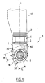
- the figures show the biboche head 1 of the invention intended to be attached to the base of a horizontal or vertical support 10 of a machine gantry (fixed or movable) or on a post, for example using a device type of hanging called "pick-up".
- the head 1 comprises a block 2 movable in rotation about the axis vertical C with a direct drive motor-torque 3, which are associated means 4 hydraulic locking of the axis C and a ring 5 of orientation with integrated measurement or cooperating with position 6.
- the fork-shaped unit 2 forms a yoke 11 in which is mounted rotating a spindle support shaft 12 about the B axis orthogonal to C.
- the support shaft 12 rotates on the one hand thanks to a journal 14 cooperating with an orientation ring 13 with integrated measurement and a device for hydraulic blocking 15 of the axis B and secondly through a pivot to bearing 16, the position measurement being provided by a rotary sensor 17 or by integrated measurement of the crown 13.
- the invention could apply to a motor head driven directly on the B axis as shown very schematically in Figures 2 and 3, it applies preferably to a head with semi-direct drive as shown in the FIG.
- the support 12 is rotated on the B axis in a semi-direct manner thanks to a gear wheel 18 equipped with a precharging device and meshing with a pinion 19 carried by the output of a control motor Located on one side of the block 2 and powered electrically by electrical connections 21 that go up through the support 10.
- a control motor Located on one side of the block 2 and powered electrically by electrical connections 21 that go up through the support 10.
- the interior of the support 10 passes hydraulic connections, pneumatic 22 and electric.
- the axes B and C are limited travel; the addition of a set of hydraulic collectors and electrical (known per se and not shown) allows rotation without limitation of the C axis
- the axes aa and bb of the pins 30 and 40 are spaced a respective distance L and M from the axis of rotation B of the support shaft 12. These distances L and M are substantially equal.
- the two pins which are also centered in the same median plane of the support shaft 12 passing through the axis C, have substantially the same space, thus limiting the risks of interference between the workpiece and the machining head, between the roughing and finishing phases. They are located for example in quadrature inverted with respect to each other, which makes it possible to change quickly machining process roughing finish.
- the parts of tools, respectively 30 'for the spindle 30, and 40' for the spindle pin 40, are diametrically opposite to the axis B, as it is see especially in Figures 1 and 4.
- the part tool drive the non-working spindle is protected at best dirt formed by the working spindle since it is diametrically distant.
Landscapes
- Engineering & Computer Science (AREA)
- Mechanical Engineering (AREA)
- Machine Tool Units (AREA)
Abstract
Description
Claims (6)
- Tête pivotante multiaxe de machine-outil, du type comportant un bloc-fourche (2) monté pivotant autour d'un premier axe C, un arbre-support (12) monté tournant autour d'un second axe B dans le bloc-fourche (2), des premiers moyens (3) d'entraínement en rotation du bloc-fourche (2) autour dudit premier axe C, des seconds moyens d'entraínement (18-20) en rotation dudit arbre-support (12) autour dudit second axe B, et deux broches (30, 40) montées à des positions angulaires différentes sur ledit arbre-support (12) et l'une des broches étant déportée de sorte que son axe (aa, bb) soit orthogonal audit second axe B, caractérisée en ce que les deux broches (30, 40) sont montées déportées sur l'arbre-support (12) de sorte que leur axe (aa, bb) soit éloigné dudit second axe B et orthogonal à celui-ci, les deux broches ayant leurs parties d'entraínement d'outil sensiblement diamétralement opposées par rapport audit second axe (B).
- Tête selon la revendication 1, caractérisée en ce qu'une broche (30) est une broche entraínée au travers d'une transmission angulaire (31) par un arbre rotor (32) d'un moteur synchrone (32, 33) logé dans ledit arbre-support tournant (12), perpendiculairement audit second axe B.
- Tête selon la revendication 2, caractérisée en ce qu'une broche (30) est une broche de puissance, disposant d'un couple important.
- Tête selon l'une quelconque des revendications 1 à 3, caractérisée en ce qu'une broche (40) est une broche de finition.
- Tête selon l'une quelconque des revendications 1 à 4, caractérisée en ce que les axes (aa, bb) des deux broches sont situés dans des plans sensiblement parallèles, perpendiculaires audit second axe (B).
- Tête selon la revendication 5, caractérisée en ce que les deux broches (30, 40) sont centrées sensiblement dans un même plan transversal de l'arbre-support (12).
Applications Claiming Priority (2)
| Application Number | Priority Date | Filing Date | Title |
|---|---|---|---|
| FR0212266A FR2845303B1 (fr) | 2002-10-03 | 2002-10-03 | Tete pivotante multiaxe de machine-outil |
| FR0212266 | 2002-10-03 |
Publications (2)
| Publication Number | Publication Date |
|---|---|
| EP1405691A1 true EP1405691A1 (fr) | 2004-04-07 |
| EP1405691B1 EP1405691B1 (fr) | 2009-11-25 |
Family
ID=31985424
Family Applications (1)
| Application Number | Title | Priority Date | Filing Date |
|---|---|---|---|
| EP20030292434 Expired - Lifetime EP1405691B1 (fr) | 2002-10-03 | 2003-10-02 | Tête pivotante multiaxe de machine-outil |
Country Status (3)
| Country | Link |
|---|---|
| EP (1) | EP1405691B1 (fr) |
| DE (1) | DE60330214D1 (fr) |
| FR (1) | FR2845303B1 (fr) |
Cited By (7)
| Publication number | Priority date | Publication date | Assignee | Title |
|---|---|---|---|---|
| EP1982793A1 (fr) * | 2007-04-16 | 2008-10-22 | Mori Seiki Co.,Ltd. | Tête universelle et machine outil disposant de cette tête universelle |
| US20100028094A1 (en) * | 2006-12-27 | 2010-02-04 | Nsk Ltd. | Spindle device, machining center including the spindle device, and method for assembling the spindle device |
| CZ302304B6 (cs) * | 2005-05-31 | 2011-02-16 | Trimill, A. S. | Polohovací a brzdicí zarízení výkyvného vretena |
| US20140300065A1 (en) * | 2011-11-21 | 2014-10-09 | Deckel Maho Pfronten Gmbh | Device for employment in a machine tool as well as machine tool |
| FR3014715A1 (fr) * | 2013-12-17 | 2015-06-19 | Forest Line Albert | Tete pivotante multiaxe mixte |
| US20180010297A1 (en) * | 2015-01-16 | 2018-01-11 | Deckel Maho Pfronten Gmbh | Machining unit for a machine tool and such a machine tool |
| CN109590490A (zh) * | 2019-01-11 | 2019-04-09 | 沈阳马卡智工科技有限公司 | 十字交叉主轴加工系统 |
Citations (12)
| Publication number | Priority date | Publication date | Assignee | Title |
|---|---|---|---|---|
| US3135071A (en) * | 1959-06-05 | 1964-06-02 | Etude Et Realisation D Omnis P | Machine tools |
| DE1502515A1 (de) * | 1964-09-10 | 1969-02-13 | Mengele & Soehne Masch Karl | Rundtisch-Schleifmaschine mit schwenkbarem Kreuzschlitten |
| US4552502A (en) * | 1983-10-07 | 1985-11-12 | Nordson Corporation | Apparatus for locking the wrist links of a work robot in the same respective relative positions to facilitate calibration of the wrist link position transducers thereof |
| EP0462940A2 (fr) * | 1990-05-23 | 1991-12-27 | Ditta Bacci Paolino Di Giuseppe Bacci Di Agostino Bacci | Machine-outil pour la fabrication de joints sur des éléments de construction de meubles ou similaires |
| DE9218976U1 (de) * | 1992-10-27 | 1996-07-11 | Heidelberger Druckmaschinen Ag, 69115 Heidelberg | Werkzeugmaschine zur spanabhebenden Bearbeitung |
| WO1997010071A1 (fr) * | 1995-09-14 | 1997-03-20 | Wenyuan Shao | Centre d'usinage composite |
| JPH10138064A (ja) * | 1996-11-05 | 1998-05-26 | Nissan Motor Co Ltd | 複合加工装置 |
| EP0885081A1 (fr) * | 1995-06-13 | 1998-12-23 | Bertsche Engineering Corp. | Tete rotative de broche a axes multiples et a entrainement direct pour fraiseuse |
| EP0976498A2 (fr) * | 1998-07-28 | 2000-02-02 | TACCHELLA MACCHINE S.p.A. | Ensemble d'usinage pour rectifieuse |
| EP1027953A2 (fr) * | 1999-02-12 | 2000-08-16 | Mitsubishi Heavy Industries, Ltd. | Dispositif d'usinage avec dispositif de positionnement de broches interchangeables et procédé pour interchanger les broches |
| EP1055485A2 (fr) * | 1999-05-07 | 2000-11-29 | Bacci Paolino Di Giuseppe Bacci Di Agostino Bacci | Machine-outil pour l'usinage d'objets de forme allongée et symétrique tels que d'éléments de construction pour chaises, meubles et autres éléments analogues |
| WO2002036302A1 (fr) * | 2000-10-31 | 2002-05-10 | Pade S.A.S. Di De Moliner Vinicio & C. | Tenonneuse |
Family Cites Families (1)
| Publication number | Priority date | Publication date | Assignee | Title |
|---|---|---|---|---|
| DE8310054U1 (de) * | 1983-04-06 | 1986-02-27 | Mantec Gesellschaft für Automatisierungs- und Handhabungssysteme mbH, 8510 Fürth | Robotergelenk |
-
2002
- 2002-10-03 FR FR0212266A patent/FR2845303B1/fr not_active Expired - Fee Related
-
2003
- 2003-10-02 EP EP20030292434 patent/EP1405691B1/fr not_active Expired - Lifetime
- 2003-10-02 DE DE60330214T patent/DE60330214D1/de not_active Expired - Lifetime
Patent Citations (12)
| Publication number | Priority date | Publication date | Assignee | Title |
|---|---|---|---|---|
| US3135071A (en) * | 1959-06-05 | 1964-06-02 | Etude Et Realisation D Omnis P | Machine tools |
| DE1502515A1 (de) * | 1964-09-10 | 1969-02-13 | Mengele & Soehne Masch Karl | Rundtisch-Schleifmaschine mit schwenkbarem Kreuzschlitten |
| US4552502A (en) * | 1983-10-07 | 1985-11-12 | Nordson Corporation | Apparatus for locking the wrist links of a work robot in the same respective relative positions to facilitate calibration of the wrist link position transducers thereof |
| EP0462940A2 (fr) * | 1990-05-23 | 1991-12-27 | Ditta Bacci Paolino Di Giuseppe Bacci Di Agostino Bacci | Machine-outil pour la fabrication de joints sur des éléments de construction de meubles ou similaires |
| DE9218976U1 (de) * | 1992-10-27 | 1996-07-11 | Heidelberger Druckmaschinen Ag, 69115 Heidelberg | Werkzeugmaschine zur spanabhebenden Bearbeitung |
| EP0885081A1 (fr) * | 1995-06-13 | 1998-12-23 | Bertsche Engineering Corp. | Tete rotative de broche a axes multiples et a entrainement direct pour fraiseuse |
| WO1997010071A1 (fr) * | 1995-09-14 | 1997-03-20 | Wenyuan Shao | Centre d'usinage composite |
| JPH10138064A (ja) * | 1996-11-05 | 1998-05-26 | Nissan Motor Co Ltd | 複合加工装置 |
| EP0976498A2 (fr) * | 1998-07-28 | 2000-02-02 | TACCHELLA MACCHINE S.p.A. | Ensemble d'usinage pour rectifieuse |
| EP1027953A2 (fr) * | 1999-02-12 | 2000-08-16 | Mitsubishi Heavy Industries, Ltd. | Dispositif d'usinage avec dispositif de positionnement de broches interchangeables et procédé pour interchanger les broches |
| EP1055485A2 (fr) * | 1999-05-07 | 2000-11-29 | Bacci Paolino Di Giuseppe Bacci Di Agostino Bacci | Machine-outil pour l'usinage d'objets de forme allongée et symétrique tels que d'éléments de construction pour chaises, meubles et autres éléments analogues |
| WO2002036302A1 (fr) * | 2000-10-31 | 2002-05-10 | Pade S.A.S. Di De Moliner Vinicio & C. | Tenonneuse |
Non-Patent Citations (1)
| Title |
|---|
| PATENT ABSTRACTS OF JAPAN vol. 1998, no. 10 31 August 1998 (1998-08-31) * |
Cited By (12)
| Publication number | Priority date | Publication date | Assignee | Title |
|---|---|---|---|---|
| CZ302304B6 (cs) * | 2005-05-31 | 2011-02-16 | Trimill, A. S. | Polohovací a brzdicí zarízení výkyvného vretena |
| US20100028094A1 (en) * | 2006-12-27 | 2010-02-04 | Nsk Ltd. | Spindle device, machining center including the spindle device, and method for assembling the spindle device |
| US8641338B2 (en) * | 2006-12-27 | 2014-02-04 | Nsk Ltd. | Spindle device, machining center including the spindle device, and method for assembling the spindle device |
| EP1982793A1 (fr) * | 2007-04-16 | 2008-10-22 | Mori Seiki Co.,Ltd. | Tête universelle et machine outil disposant de cette tête universelle |
| US20140300065A1 (en) * | 2011-11-21 | 2014-10-09 | Deckel Maho Pfronten Gmbh | Device for employment in a machine tool as well as machine tool |
| US9505060B2 (en) * | 2011-11-21 | 2016-11-29 | Deckel Maho Pfronten Gmbh | Device for employment in a machine tool as well as machine tool |
| FR3014715A1 (fr) * | 2013-12-17 | 2015-06-19 | Forest Line Albert | Tete pivotante multiaxe mixte |
| WO2015092228A1 (fr) * | 2013-12-17 | 2015-06-25 | Fives Forest-Line | Tête pivotante multiaxe mixte |
| US20160311079A1 (en) * | 2013-12-17 | 2016-10-27 | Fives Machining | Mixed multiaxial pivoting head |
| US20180010297A1 (en) * | 2015-01-16 | 2018-01-11 | Deckel Maho Pfronten Gmbh | Machining unit for a machine tool and such a machine tool |
| US10480124B2 (en) * | 2015-01-16 | 2019-11-19 | Deckel Maho Pfronten Gmbh | Machining unit for a machine tool and such a machine tool |
| CN109590490A (zh) * | 2019-01-11 | 2019-04-09 | 沈阳马卡智工科技有限公司 | 十字交叉主轴加工系统 |
Also Published As
| Publication number | Publication date |
|---|---|
| FR2845303B1 (fr) | 2005-07-08 |
| FR2845303A1 (fr) | 2004-04-09 |
| EP1405691B1 (fr) | 2009-11-25 |
| DE60330214D1 (de) | 2010-01-07 |
Similar Documents
| Publication | Publication Date | Title |
|---|---|---|
| FR2825940A1 (fr) | Machine multiposte a transfert rotatif pour usinage de pieces | |
| FR2565139A1 (fr) | Machine-outil a deux broches porte-piece | |
| FR2563454A1 (fr) | Machine-outil multi-fonctions a deux broches | |
| EP1405691B1 (fr) | Tête pivotante multiaxe de machine-outil | |
| FR2560541A1 (fr) | Machine executant diverses operations d'usinage, telles que tournage, fraisage, alesage | |
| FR2582978A1 (fr) | Tete articulee pour robot industriel et robot equipe d'une telle tete | |
| FR2912676A1 (fr) | Tete d'actionnement pour machines-outils automatiques | |
| WO2009109721A2 (fr) | Tete de fraisage comportant une articulation de type cardan | |
| EP0504295B1 (fr) | Tour de decolletage a poupee fixe et broche de reprise | |
| EP2380699B1 (fr) | Indexage d'un barillet d'un tour multibroches | |
| EP1172175A2 (fr) | Système de modularité applicable au bélier-tête d'une fraiseuse | |
| FR2568801A1 (fr) | Dispositif de tete d'usinage tournante pour machines-outils automatiques | |
| EP0240438A1 (fr) | Dispositif de poignet pour robot industriel | |
| EP0686451B1 (fr) | Dispositif de taillage de pièces sur un tour | |
| EP0627969B1 (fr) | Procede et dispositif de taillage en couteau-fraise par generation | |
| EP4084922B1 (fr) | Electro-broche a avance integree avec changement automatique de porte-outil | |
| CN214674751U (zh) | 一种用于磨豆机少齿差减速机构 | |
| CH668206A5 (en) | Multi-purpose machine tool - has tool table supporting two or more tools which can be rotated at widely-differing speeds through drives and control unit | |
| FR2909913A1 (fr) | Broche a entrainement direct, centre d'usinage et son procede de fabrication | |
| FR2631864A1 (en) | Multi-function machining head for machine tools | |
| CH507046A (fr) | Fraiseuse-aléseuse | |
| FR2606310A1 (fr) | Machine-outil multifonction | |
| JPH05237711A (ja) | 回転工具ホルダ | |
| CH610797A5 (en) | Machine tool | |
| FR2564012A1 (fr) | Plateau d'alesage-dressage, notamment pour ensemble d'usinage a tetes interchangeables |
Legal Events
| Date | Code | Title | Description |
|---|---|---|---|
| PUAI | Public reference made under article 153(3) epc to a published international application that has entered the european phase |
Free format text: ORIGINAL CODE: 0009012 |
|
| AK | Designated contracting states |
Kind code of ref document: A1 Designated state(s): AT BE BG CH CY CZ DE DK EE ES FI FR GB GR HU IE IT LI LU MC NL PT RO SE SI SK TR |
|
| AX | Request for extension of the european patent |
Extension state: AL LT LV MK |
|
| 17P | Request for examination filed |
Effective date: 20041007 |
|
| AKX | Designation fees paid |
Designated state(s): DE FR IT |
|
| 17Q | First examination report despatched |
Effective date: 20080801 |
|
| GRAP | Despatch of communication of intention to grant a patent |
Free format text: ORIGINAL CODE: EPIDOSNIGR1 |
|
| GRAS | Grant fee paid |
Free format text: ORIGINAL CODE: EPIDOSNIGR3 |
|
| GRAA | (expected) grant |
Free format text: ORIGINAL CODE: 0009210 |
|
| AK | Designated contracting states |
Kind code of ref document: B1 Designated state(s): DE FR IT |
|
| REF | Corresponds to: |
Ref document number: 60330214 Country of ref document: DE Date of ref document: 20100107 Kind code of ref document: P |
|
| PLBE | No opposition filed within time limit |
Free format text: ORIGINAL CODE: 0009261 |
|
| STAA | Information on the status of an ep patent application or granted ep patent |
Free format text: STATUS: NO OPPOSITION FILED WITHIN TIME LIMIT |
|
| 26N | No opposition filed |
Effective date: 20100826 |
|
| REG | Reference to a national code |
Ref country code: FR Ref legal event code: CA Effective date: 20140221 |
|
| REG | Reference to a national code |
Ref country code: FR Ref legal event code: PLFP Year of fee payment: 14 |
|
| REG | Reference to a national code |
Ref country code: FR Ref legal event code: PLFP Year of fee payment: 15 |
|
| REG | Reference to a national code |
Ref country code: FR Ref legal event code: PLFP Year of fee payment: 16 |
|
| PGFP | Annual fee paid to national office [announced via postgrant information from national office to epo] |
Ref country code: FR Payment date: 20220921 Year of fee payment: 20 |
|
| PGFP | Annual fee paid to national office [announced via postgrant information from national office to epo] |
Ref country code: IT Payment date: 20220920 Year of fee payment: 20 Ref country code: DE Payment date: 20220920 Year of fee payment: 20 |
|
| REG | Reference to a national code |
Ref country code: DE Ref legal event code: R071 Ref document number: 60330214 Country of ref document: DE |