EP0462940A2 - Machine-outil pour la fabrication de joints sur des éléments de construction de meubles ou similaires - Google Patents
Machine-outil pour la fabrication de joints sur des éléments de construction de meubles ou similaires Download PDFInfo
- Publication number
- EP0462940A2 EP0462940A2 EP91830211A EP91830211A EP0462940A2 EP 0462940 A2 EP0462940 A2 EP 0462940A2 EP 91830211 A EP91830211 A EP 91830211A EP 91830211 A EP91830211 A EP 91830211A EP 0462940 A2 EP0462940 A2 EP 0462940A2
- Authority
- EP
- European Patent Office
- Prior art keywords
- axis
- axes
- tool
- spindle
- unit according
- Prior art date
- Legal status (The legal status is an assumption and is not a legal conclusion. Google has not performed a legal analysis and makes no representation as to the accuracy of the status listed.)
- Granted
Links
Images




Classifications
-
- B—PERFORMING OPERATIONS; TRANSPORTING
- B27—WORKING OR PRESERVING WOOD OR SIMILAR MATERIAL; NAILING OR STAPLING MACHINES IN GENERAL
- B27C—PLANING, DRILLING, MILLING, TURNING OR UNIVERSAL MACHINES FOR WOOD OR SIMILAR MATERIAL
- B27C5/00—Machines designed for producing special profiles or shaped work, e.g. by rotary cutters; Equipment therefor
-
- B—PERFORMING OPERATIONS; TRANSPORTING
- B27—WORKING OR PRESERVING WOOD OR SIMILAR MATERIAL; NAILING OR STAPLING MACHINES IN GENERAL
- B27C—PLANING, DRILLING, MILLING, TURNING OR UNIVERSAL MACHINES FOR WOOD OR SIMILAR MATERIAL
- B27C9/00—Multi-purpose machines; Universal machines; Equipment therefor
- B27C9/04—Multi-purpose machines; Universal machines; Equipment therefor with a plurality of working spindles
-
- B—PERFORMING OPERATIONS; TRANSPORTING
- B27—WORKING OR PRESERVING WOOD OR SIMILAR MATERIAL; NAILING OR STAPLING MACHINES IN GENERAL
- B27F—DOVETAILED WORK; TENONS; SLOTTING MACHINES FOR WOOD OR SIMILAR MATERIAL; NAILING OR STAPLING MACHINES
- B27F1/00—Dovetailed work; Tenons; Making tongues or grooves; Groove- and- tongue jointed work; Finger- joints
- B27F1/02—Making tongues or grooves, of indefinite length
-
- B—PERFORMING OPERATIONS; TRANSPORTING
- B27—WORKING OR PRESERVING WOOD OR SIMILAR MATERIAL; NAILING OR STAPLING MACHINES IN GENERAL
- B27F—DOVETAILED WORK; TENONS; SLOTTING MACHINES FOR WOOD OR SIMILAR MATERIAL; NAILING OR STAPLING MACHINES
- B27F1/00—Dovetailed work; Tenons; Making tongues or grooves; Groove- and- tongue jointed work; Finger- joints
- B27F1/08—Making dovetails, tongues, or tenons, of definite limited length
- B27F1/10—Cutting tenons of round or rounded- off profile
-
- B—PERFORMING OPERATIONS; TRANSPORTING
- B27—WORKING OR PRESERVING WOOD OR SIMILAR MATERIAL; NAILING OR STAPLING MACHINES IN GENERAL
- B27G—ACCESSORY MACHINES OR APPARATUS FOR WORKING WOOD OR SIMILAR MATERIALS; TOOLS FOR WORKING WOOD OR SIMILAR MATERIALS; SAFETY DEVICES FOR WOOD WORKING MACHINES OR TOOLS
- B27G19/00—Safety guards or devices specially adapted for wood saws; Auxiliary devices facilitating proper operation of wood saws
- B27G19/10—Measures preventing splintering of sawn portions of wood
Definitions
- the invention relates to a numerically controlled processing unit for processing connections on structural elements of furniture and. Like., For example on armrests or other elements of chairs and upholstered furniture, frame strips and other objects.
- the invention also relates to a numerically controlled machine with one or more such machining units, in particular to a machine with two mutually opposite machining units for simultaneous machining of two end regions of the same workpiece.
- the invention has for its object to provide a numerically controlled processing unit that can form not only the pin, but also the pin holes and can also carry out butt joints and the milling of structural elements of furniture or the like ..
- a numerically controlled processing unit for machines for processing the end portions of structural elements of furniture and.
- a head which carries at least two tools with parallel axes, one of which executes a continuous working movement along two translation axes, while the other is movable in the direction of three translation axes, the tools having an axis of rotation which is parallel to one of the three mentioned Translational axes, and at least the other two axes, which determine an interpolation level, are common to both tools and are numerically controlled.
- This not only ensures that the directions of the working axes coincide, but also that the two tools are controlled in their movement in two directions together by common mechanical organs and control systems.
- the tools and the workpiece perform a relative pivoting movement about two orthogonal or approximately orthogonal axes.
- the first tool which can be moved numerically controlled along two axes perpendicular to its own axis of rotation, can form the abutment and / or pin, ie the male connecting part.
- the second tool which is numerically controlled along at least two axes and along a third axis parallel to its own axis of rotation, can either form holes with a circular cross-section or pin holes, i.e. recesses with an elongated cross-section, which form the female connecting part into which a pin or a dowel can be used.
- the holes can be multiple holes and have any axis spacing.
- the swiveling movement of the tools enables the formation of both holes and mortises with variable inclinations.
- the machine designed in this way is suitable for producing all types of connections, in particular pins / mortise and tenon joints of any shape. Both tools are then able to Machining contours, ie forming bevels along the front edges of parts with any cross-section.
- the great flexibility of the machining unit can be achieved with two or at most three axes with numerical control, since the translation and machining axis of the first tool coincide with two of the translation and machining axis of the second tool. This enables the manufacture of a comparatively inexpensive and easy-to-use unit.
- the relative pivoting movement between the head and the workpiece is advantageously carried out by the workpiece if only one processing unit is provided. If, on the other hand, two processing units are provided which process the same workpiece at the same time, each of them has a head which can be pivoted about two orthogonal axes.
- the two tools are advantageously arranged coaxially.
- the first tool can be a milling machine, while the second tool can be a drill, a milling machine, a milling machine or the like, which are mounted on the same spindle and can be moved axially relative to the first tool.
- the first tool is also used to create the butt or butt of the workpiece, creating chips that can be easily removed.
- the working head is movable along a substantially horizontal axis, so that the two tools carried by this head are displaceable along two essentially horizontal skewed axes and can rotate relative to one another about a vertical axis.
- This enables the machine to perform work on planes that are strongly inclined relative to the length of the workpiece.
- the processing unit can work in directions that are inclined within an arc of more than 90 °. It also enables the processing of elements with a semicircular shape.
- a further spindle is provided, the axis of which lies in a plane which is essentially perpendicular to the axis of rotation of the first tool.
- This further spindle can be moved along three translation and working axes. It carries a milling cutter, referred to below as a sub-milling cutter, which can carry out milling work on the workpiece with different inclinations.
- the inclination of the spindle of the sub-mill can advantageously be adjusted in the plane perpendicular to the axis of rotation of the first tool.
- the spindle can also carry a second tool that is coaxial with the sub-router, for example a drill or a cutter, which is either fixed or axially displaceable relative to the sub-router can be ordered.
- the translation and working axes of the spindle of the sub-router are advantageously the same as those of the other two tools, in the sense that the drive and control systems of the first two tools can also be used for the translation movement of the further spindle.
- the processing unit is equipped with three tools which can be controlled along two common translation and working axes, while two of these tools can be controlled in the direction of a third translation axis, the latter also being jointly and numerically controlled for the two tools mentioned.
- the first tool and the sub-router could advantageously be quasi superimposed so that the end areas of small workpieces with a semicircular or similar development can be machined simultaneously with two processing units.
- this arrangement makes it possible to carry out machining operations in succession with the sub-mill and with the first tool and, if appropriate, with the second tool, without large displacements of the head of the machining unit being required, so that the overall space requirement of the machine is small overall.
- the spindle carrying the sub-mill is advantageously mounted on a slide which is movable parallel to the axis of rotation of the first tool.
- Means for anchoring the second tool can be arranged on the carriage in order to displace it in the axial direction, so that the movements of both the sub-router and the second tool can be carried out with a single numerically controlled axis.
- the further spindle can also carry a multiple tool, which may have zones with cutting edges that can work in opposite directions of rotation. As is made clear in the further description, this serves to carry out work in which a breakout of a wood is to be prevented.
- the movement of the spindle in the direction of the translation and working axes enables one or the other zone of the assembled tool to be brought into the working position.
- the direction of rotation of the assembled tool can be reversed using the same drive that is used to carry out other movements of the processing unit or of the machines containing it.
- the same drive can be used both to control the reversal of the direction of rotation of the sub-router and subsequently to control the movements according to the pivot axis and / or the movements of the loading device carrying the workpieces and / or the movements of the mutual approach and distance between two Machining units that are mounted on the same machine. This is possible because the movements mentioned follow one another and do not occur simultaneously.
- the head can be vertically displaceable along a further translation axis.
- the invention further relates to a machine tool with one or more machining units of the type described above.
- the machine according to the invention can in particular comprise two such machining units, one of which can be moved along the machine frame, moving towards or away from the other around the two To be able to process end areas of an element at the same time, whereby the elements to be processed can have very different dimensions.
- the special arrangement of the tools on the head of each processing unit enables the processing of workpieces of very short length.
- the two processing units of the machine are advantageously controlled independently of one another, so that different work on the end regions of the Workpiece can be performed.
- An automatic loading device can be arranged between the two units.
- FIGS. 1 and 2 show a schematic representation of a machine 1 with two processing units 3 and 5, respectively.
- the schematic representation of FIGS. 1 and 2 serves to explain the movement possibilities and the degrees of freedom of the machine, the structural details of which with reference to FIGS. 3 and the following are explained in more detail.
- the processing units 3 and 4 are arranged on a machine housing 5, on which guides 7 are formed, on which one of the two working units (in the example shown, the unit 5) can be moved relative to the other. The movement of the approach and distance takes place in the direction of arrow D (Fig. 1).
- the movement of the movable processing unit 5 in the direction of arrow D is brought about by a geared motor 8 which carries a threaded rod 10.
- Two semi-loaders 9 and 11 are also arranged on the housing 4 and can be moved relative to one another along the guides 7 of the arrow C.
- the movement of the semi-loaders 9 and 11 enables their positioning relative to the processing units 3 and 5 and the adjustment of the space between them in order to machine workpieces of different dimensions.
- the semi-trailers are moved by geared motors 12 and 14 relative to the processing units 3 and 5.
- Each of the two processing units 3 and 5 has a frame 13 and 15, respectively, which is horizontally and transversely displaceable relative to the housing 4 in the direction of arrow P and vertically in the direction of arrow Q.
- the frame 13 or 15 can also perform a pivoting movement in the direction of arrow B about a vertical axis.
- the unit 3 is moved in the horizontal direction P by a geared motor 17, the unit 5 by a geared motor 19.
- the pivoting movement of the machining unit 3 in the direction of arrow B around the vertical axis is driven by a geared motor 21, that of the machining unit 5 by a Gear motor 23.
- Each of the machining units 3 and 5 carries a head 25 and 27, on which the spindles and the machining tools are mounted.
- the two heads 25 and 27 can each perform a pivoting movement in the direction of arrow A about a horizontal axis.
- the head 25 carries a first spindle for two lower coaxial tools 31 and 33 which rotate about an axis which runs horizontally when the head has a zero inclination about its own horizontal pivot axis.
- the lower tool 31 is subjected to a movement along two mutually perpendicular directions X and Y, while the second lower tool 33 and the upper tool 35 are subjected to a movement along three mutually perpendicular directions X, Y and Z.
- the head 15 is equipped with three tools, which correspond to the tools 31, 33, 35 and are labeled 37, 39 and 41, respectively.
- each processing unit is thus subjected to a translational movement along a horizontal axis P and a vertical axis Q and with a pivoting movement corresponding to the axis B.
- the head of the processing unit is subjected to a swiveling movement along the axis A, while the tools 33, 35 and 39, 41 with translation movements along the axes X, Y and Z and the tools 31 and 27 with a translation movement only along the axes X and Y be charged.
- All axes A, B, C, D, P, Q, X, Y, Z of each processing unit are advantageously numerically controlled.
- the tool 31 of the machining unit 3 which is numerically controlled along the interpolation axes X, Y, can strike a workpiece on a flat surface that is inclined up to 90 ° with respect to a plane that is vertical to the housing 4 of the machine.
- the processing unit according to the invention can also push workpieces with a semicircular shape, in which the surface to be pushed is therefore parallel to the axis D and vertical plane.
- the tool 31 can be brought to the side of the workpiece by moving the machining unit along the axis P from the center line of the housing 4 and then rotating the head according to the control axis B (i.e. around a vertical geometric axis). In this way, the tool 31 can access the workpiece in the direction of the arrow f1 (FIG. 2).
- the degree of freedom of the head 25 along the control axis A enables the tool 31 to machine non-vertical surfaces.
- the tool 31 which is numerically controlled along the interpolation axes X, Y, is not only able to abut the workpiece, but also to produce pins, ie the male connecting parts.
- the numerical control enables the use of a burr (with an axis of rotation parallel to the Z axis) and a circular blade as in conventional machines. Together with the possibility of numerical control of the tool along the X and Y axes, this results in two important advantages: in contrast to machines with circular blades that produce large chips that cannot be extracted, chip-shaped waste is generated that can be extracted. This enables easier removal of the waste and thus a more reliable functioning of the machine.
- the action of the milling cutters on the workpiece is directed from the outside in, thereby preventing the wood from breaking out which can occur with conventional circular cutters when they emerge from the wood.
- the use of a milling cutter instead of a circular blade also considerably reduces the size of the tool, so that an automatic loader can be used even when the machining unit is very inclined.
- the tool 33 arranged coaxially to the tool 31 is numerically controlled in the direction of the interpolation axes X, Y and the axis Z.
- the X axis is also a numerically controlled axis.
- the control axes P, X and B the tool 33 as well as the tool 31 can access the workpiece in any direction within an arc of more than 90 ° and therefore also work in the direction f1 (FIG. 2).
- the numerical control of the tool 33 enables the execution of both simple holes and pin holes.
- the control along The axes X and Y enable the tool 33 to be executed in the journal holes with any shape, axis distance, inclination and dimensions.
- the tool 33 can be a drill or a milling machine or a milling machine.
- the numerical control along the Z axis enables the production of holes or mortises with variable and controlled depth.
- the tools 31 and 33 can also carry out contour machining on the workpiece.
- the processing unit according to the invention (and thus the machine equipped with it) is capable to carry out a larger range of operations with greater flexibility than normal tenoning machines and normal butt joint punching machines.
- a machine that is equipped with one or preferably two machining units of the type of machining units 3 and 5 butt butt-tenoning-mortise and milling work can be carried out on one or two end regions of workpieces of any shape. In addition to increasing the range of motion of the machine, this also gives you the option of using perform one and the same machine for which previously different machines were necessary.
- the further tool 35 which is referred to below as a milling cutter, expands the possibilities of the machining unit.
- the axis of rotation of the sub-router 35 can be inclined in the plane defined by the interpolation axes X, Y. It can therefore assume any inclination in this plane and carry out milling work that is inclined with respect to the axes X and Y.
- the spindle carrying the router can be moved along the three-numerically controlled axes X, Y and Z.
- a drill can optionally be provided on the spindle carrying the sub-router, which is arranged coaxially with the sub-router 35 and is fixedly or axially movable relative to the latter.
- the sub-router enables milling work to be carried out which are inclined in the planes X, Y and have any inclination around the control axes A and B.
- the optionally provided drill also enables the production of bores or mortises in a plane that is perpendicular to the axis of rotation of the sub-router.
- the numerical control of the router also has another advantage.
- the router 35 When the router cuts out of the wood to prevent the wood from breaking out, the milling process can be interrupted before the tool emerges from the wood.
- the router is then removed from the wood in the Z axis direction, its direction of rotation is reversed, it is moved along its own axis of rotation to change the tool, and then it is moved along the X and / or Y and / or Z axes to that Resume editing from the side opposite the page from which it started. In this way, the tool never ends the machining in the area of the outer surface of the workpiece, and chipping of the wood is avoided.
- the processing unit 3 is explained in more detail below with reference to FIGS. 3-9.
- the processing unit 5 is equivalent and is therefore not described in detail.
- the processing unit 3 has a base 51 which is fastened to a threaded rod 55 via a nut 53 (FIG. 7).
- the threaded rod 55 is mounted on the housing 4 and is rotated by a gear motor 17 which controls the movement of the processing unit 3 in the direction of the horizontal axis P.
- a vertical column 57 is arranged on the base 51 and can be pivoted about the control axis B by the geared motor 21.
- the rotational movement is controlled by a pinion 59, which meshes with a tooth sector 61.
- a tubular member 63 (FIG.
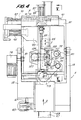
- the frame 13 and the associated head 25 with the spindles and the tools mounted thereon are shown in detail.
- the frame 13 carries a geared motor 79 which, via a pinion 81 which engages with the toothed sector 83 which is fixedly connected to the head 25, causes the head 25 to pivot about the control axis A.
- two guides 91 are arranged on which a slide 93 slides, which can be moved in the direction of the X axis. In the following, this slide is referred to as a horizontal slide.
- the movement of the horizontal slide is controlled by a motor 95 via a threaded rod 97 controlled.
- the carriage 93 carries a plate 99 on which two guides 101 are mounted for the sliding movement of a further carriage 103, which is referred to below as a vertical carriage.
- the vertical slide 103 moves along the Y axis with the aid of a threaded rod 105, which is rotated by a motor 107 via a belt 109.
- the vertical slide 103 carries at the bottom a spindle 111 carrying a milling cutter, on which the tools 31 and 33 are mounted.
- the spindle 111 is described in more detail below with reference to FIG. 9.
- the tools 31 and 33 are driven by a motor 113 through a belt 115.
- the vertical slide also carries a pair of guides 117 on which another slide 119, hereinafter referred to as a sub-milling cutter, can slide, which can be moved along the Z axis.
- a sub-milling cutter On the carriage carrying the sub-mill, two holders 121 are arranged which carry an element 123 on which the spindle 125 of the sub-mill 35 is mounted, which is illustrated in an axial section in FIG.
- the brackets 121 of the element 123 can be released to change the inclination of the axis of the spindle 125 in the plane defined by the axes X and Y.
- the movement of the carriage 119 carrying the sub-mill along the axis Z is carried out by a motor 127 and a belt 129, which control the rotary movement of a threaded rod 131.
- the Rotation of the sub-mill is done by a rear motor 133 by means of a belt 135.
- the spindles 111 and 125 are virtually superimposed vertically in order to substantially reduce the space requirement of the head in the direction of the X axis.
- the arrangement of the tools is asymmetrical with respect to the head 25, i.e. the two spindles and the associated tools are arranged on the same side (on the right in FIG. 4) of the central planes of the head and can be displaced in the direction X until they practically abut the side of the head and thus the processing unit.
- This is very advantageous if one and the same workpiece with small dimensions is to be machined with two machining units 3, 5, which is approached in directions that are essentially perpendicular to the longitudinal expansion of the machine housing. Since the tools are arranged asymmetrically on the heads concerned and can approach the flanks of the processing units in question, the tools of the two units can be arranged very close to one another during processing.
- the spindles 111 and 125 are rigidly one above the other and do not perform any relative movements in the X and / or Y direction can, while the spindle of the router has wide movement along the Z axis. This makes it possible for the sub-router to coincide with the underlying tools 31 and 33 and to work with the latter without the sub-router overlapping with the workpiece.
- the spindles are arranged in a special way so that all tools 31, 33, 35 are controlled along common axes X and Y. This allows great flexibility in machining, combined with a considerable simplification of the control, since three tools can be moved on two spindles with a control unit in two vertical directions, the control unit controlling only two axes (for these two movements).
- the sub-router 35 can be composed of a multiple tool, ie of a series of tools 35 A, 35 B, 35 C, 35 D lying one above the other with cutting edges that rotate in the opposite direction.
- the tools 35 A and 35 D can be used, for example, to carry out comb milling and rotate clockwise or counterclockwise. These two tools are used in combination to carry out part of the milling work, which, as explained above, prevents the wood from breaking out.
- FIG. 9 shows an axial section of the spindle 111 carrying the mill.
- the spindle 111 carries a first tubular shaft 141 on which a pulley 43 is wedged, which takes over the movement of the motor 113 via the belt 115.
- the tubular shaft 141 carries the milling cutter 31.
- a second shaft 145 is arranged coaxially in the tubular shaft 141, on which the tool 33 is mounted by means of a shaft 147. In its central position, the shaft 145 has a series of long grooves 149 in which corresponding tongues 151 slide, which are firmly connected to the tubular shaft 151.
- the grooves 149 and the tongues 151 form a coupling between the two shafts 141 and 145, so that the shaft 145 is rotatably connected to the shaft 141, but can slide axially relative to the latter.
- Two pneumatic cylinder-piston systems 143 are attached to the spindle 111, only one of which is visible in FIG.
- the pistons of the cylinder-piston systems 153 are connected to the inner shaft 145 via columns 155 and form elastic members which bias the shaft 145 into the retracted position, i.e. to the position in which the tool 33 is set back relative to the active surface of the tool 31, as shown in FIG.
- the advancement of the shaft 145 and the tool 33 is achieved in that it is temporarily connected to the carriage 119 carrying the sub-mill. If this Carriage 119 is completely retracted, a pneumatic cylinder-piston system 160 (FIG. 5), which is connected to shaft 145 via a bracket 162, pulls out a hook element which connects shaft 145 to a plate 164, which in turn is fixed to the carriage 119 is connected. The subsequent forward and backward movement of the slide 119 is thus transmitted to the tool 33, which can therefore move along the X axis and also along the X and Y axes.
- a numerically controlled axis Z is jointly available for the movement of the spindle 125 (and thus of the lower milling cutter) and the tool 33. Therefore, the translation movements of all tools of the machining unit can be controlled in three orthogonal axes with a numerical control unit that masters the three translation axes X, Y and Z.
Landscapes
- Life Sciences & Earth Sciences (AREA)
- Engineering & Computer Science (AREA)
- Wood Science & Technology (AREA)
- Mechanical Engineering (AREA)
- Forests & Forestry (AREA)
- Conveying And Assembling Of Building Elements In Situ (AREA)
- Machine Tool Units (AREA)
- Numerical Control (AREA)
- Milling Processes (AREA)
- Perforating, Stamping-Out Or Severing By Means Other Than Cutting (AREA)
- Milling, Drilling, And Turning Of Wood (AREA)
- Mutual Connection Of Rods And Tubes (AREA)
Applications Claiming Priority (2)
| Application Number | Priority Date | Filing Date | Title |
|---|---|---|---|
| IT940290 | 1990-05-23 | ||
| IT9402A IT1238935B (it) | 1990-05-23 | 1990-05-23 | Macchina utensile per la realizzazione di giunti su elementi costruttivi di mobili e simili |
Publications (3)
| Publication Number | Publication Date |
|---|---|
| EP0462940A2 true EP0462940A2 (fr) | 1991-12-27 |
| EP0462940A3 EP0462940A3 (en) | 1992-05-06 |
| EP0462940B1 EP0462940B1 (fr) | 1994-09-07 |
Family
ID=11129605
Family Applications (1)
| Application Number | Title | Priority Date | Filing Date |
|---|---|---|---|
| EP91830211A Expired - Lifetime EP0462940B1 (fr) | 1990-05-23 | 1991-05-21 | Machine-outil pour la fabrication de joints sur des éléments de construction de meubles ou similaires |
Country Status (5)
| Country | Link |
|---|---|
| EP (1) | EP0462940B1 (fr) |
| AT (1) | ATE111010T1 (fr) |
| DE (2) | DE9016128U1 (fr) |
| ES (1) | ES2060341T3 (fr) |
| IT (1) | IT1238935B (fr) |
Cited By (11)
| Publication number | Priority date | Publication date | Assignee | Title |
|---|---|---|---|---|
| FR2696971A1 (fr) * | 1992-10-19 | 1994-04-22 | Gouaze Pierre | Machine à faire les assemblages en queue d'aronde et de femelle. |
| EP0606052A1 (fr) * | 1992-12-30 | 1994-07-13 | Ditta Bacci Paolino Di Giuseppe Bacci Di Agostino Bacci | Unité d'usinage à deux broches pour machine-outil, pour usiner des pièces en bois ou similaire |
| EP1050387A1 (fr) * | 1999-05-06 | 2000-11-08 | Pade S.a.s. di De Moliner Vinicio & C. | Machine pour usiner les extrémités d'éléments pour meubles et similaires |
| FR2799150A1 (fr) * | 1999-10-02 | 2001-04-06 | Christian Marie Alai Charpenet | Dispositif automatise d'usinage d'elements en bois |
| WO2002036302A1 (fr) * | 2000-10-31 | 2002-05-10 | Pade S.A.S. Di De Moliner Vinicio & C. | Tenonneuse |
| EP1405691A1 (fr) * | 2002-10-03 | 2004-04-07 | Forest Line Albert | Tête pivotante multiaxe de machine-outil |
| EP1623805A1 (fr) * | 2004-08-02 | 2006-02-08 | Balestrini Renzo S.p.A. | Machine à contrôle numérique pour la réalisation d'éléments de jonction |
| EP1992449A1 (fr) | 2007-05-11 | 2008-11-19 | Paolino Bacci S.R.L. | Centre d'usinage et procédé d usinage |
| DE102011106230A1 (de) * | 2011-06-24 | 2012-12-27 | Reichenbacher Hamuel Gmbh | Bearbeitungsmaschine |
| CN103692529A (zh) * | 2013-12-03 | 2014-04-02 | 华南农业大学 | 一种双机械手双主轴组合式的木材柔性复合加工装置 |
| WO2019182046A1 (fr) * | 2018-03-22 | 2019-09-26 | 国立大学法人千葉大学 | Système de traitement de bois |
Families Citing this family (4)
| Publication number | Priority date | Publication date | Assignee | Title |
|---|---|---|---|---|
| IT1238935B (it) * | 1990-05-23 | 1993-09-07 | Bacci Paolino Di Giuseppe Bacc | Macchina utensile per la realizzazione di giunti su elementi costruttivi di mobili e simili |
| DE4115095A1 (de) * | 1991-05-08 | 1992-11-12 | Hans Hundegger | Rotierendes fraeswerkzeug |
| DE19624138A1 (de) * | 1996-06-17 | 1997-12-18 | Hans Hundegger | Abbundanlage zur Bearbeitung von Strangmaterial |
| IT1397634B1 (it) * | 2010-01-22 | 2013-01-18 | Scm Group Spa | Macchina angolare. |
Family Cites Families (14)
| Publication number | Priority date | Publication date | Assignee | Title |
|---|---|---|---|---|
| US1968091A (en) * | 1931-02-13 | 1934-07-31 | John M Nash | Machine for shaping bar ends, and work end finishing purposes |
| CH280908A (de) * | 1950-04-14 | 1952-02-15 | Koeberle Albert | Doppelfräsmaschine für Holzbearbeitung. |
| US3923086A (en) * | 1974-02-25 | 1975-12-02 | Jr Daniel M Spohn | Adjustable radial arm apparatus for use with a router or the like |
| DE3024701A1 (de) * | 1980-06-30 | 1982-01-28 | Industrie-Planungs-Gesellschaft Mbh, 8380 Landau | Vorrichtung zum abbinden von hoelzern, wandteilen o.dgl. |
| NL8102437A (nl) * | 1981-05-18 | 1982-12-16 | Helmes Maschf Bv | Dubbelzijdige pennenbank. |
| IT8220780U1 (it) * | 1982-02-10 | 1983-08-10 | Celaschi S R L | Squadratrice doppia automatica per la lavorazione del legno, di struttura alquanto compatta e a frese multiple. |
| US4589174A (en) * | 1984-03-27 | 1986-05-20 | Brigham Young University | Polar coordinate apparatus |
| US4631799A (en) * | 1984-11-05 | 1986-12-30 | Alexander Dodds Company | Combined motorizing and drilling machine |
| FR2612826A1 (fr) * | 1987-03-24 | 1988-09-30 | Houiller Louis | Machine-outil pour le travail de pieces de bois |
| NO170463C (no) * | 1987-05-23 | 1992-10-21 | Hirsch Wilhelm | Trebearbeidelsesmaskin |
| DE3807730A1 (de) * | 1988-03-09 | 1989-09-21 | Will E C H Gmbh & Co | Stelleinrichtung zum veraendern der positionen von gefuehrten einheiten an maschinen |
| EP0348536A1 (fr) * | 1988-06-25 | 1990-01-03 | BALJER & ZEMBROD GmbH & Co. | Machine-outil pour l'usinage de poutrelles |
| DE8907625U1 (de) * | 1989-06-22 | 1989-09-07 | Willi Stürtz GmbH, Maschinenbau, 5466 Neustadt | Vorrichtung zur Herstellung von Öffnungen od.dgl. an Rahmen |
| IT1238935B (it) * | 1990-05-23 | 1993-09-07 | Bacci Paolino Di Giuseppe Bacc | Macchina utensile per la realizzazione di giunti su elementi costruttivi di mobili e simili |
-
1990
- 1990-05-23 IT IT9402A patent/IT1238935B/it active IP Right Grant
- 1990-11-27 DE DE9016128U patent/DE9016128U1/de not_active Expired - Lifetime
-
1991
- 1991-05-21 AT AT91830211T patent/ATE111010T1/de not_active IP Right Cessation
- 1991-05-21 DE DE59102812T patent/DE59102812D1/de not_active Expired - Fee Related
- 1991-05-21 EP EP91830211A patent/EP0462940B1/fr not_active Expired - Lifetime
- 1991-05-21 ES ES91830211T patent/ES2060341T3/es not_active Expired - Lifetime
Cited By (16)
| Publication number | Priority date | Publication date | Assignee | Title |
|---|---|---|---|---|
| FR2696971A1 (fr) * | 1992-10-19 | 1994-04-22 | Gouaze Pierre | Machine à faire les assemblages en queue d'aronde et de femelle. |
| EP0606052A1 (fr) * | 1992-12-30 | 1994-07-13 | Ditta Bacci Paolino Di Giuseppe Bacci Di Agostino Bacci | Unité d'usinage à deux broches pour machine-outil, pour usiner des pièces en bois ou similaire |
| EP1050387A1 (fr) * | 1999-05-06 | 2000-11-08 | Pade S.a.s. di De Moliner Vinicio & C. | Machine pour usiner les extrémités d'éléments pour meubles et similaires |
| FR2799150A1 (fr) * | 1999-10-02 | 2001-04-06 | Christian Marie Alai Charpenet | Dispositif automatise d'usinage d'elements en bois |
| WO2002036302A1 (fr) * | 2000-10-31 | 2002-05-10 | Pade S.A.S. Di De Moliner Vinicio & C. | Tenonneuse |
| EP1405691A1 (fr) * | 2002-10-03 | 2004-04-07 | Forest Line Albert | Tête pivotante multiaxe de machine-outil |
| FR2845303A1 (fr) * | 2002-10-03 | 2004-04-09 | Forest Line Albert | Tete pivotante multiaxe de machine-outil |
| EP1623805A1 (fr) * | 2004-08-02 | 2006-02-08 | Balestrini Renzo S.p.A. | Machine à contrôle numérique pour la réalisation d'éléments de jonction |
| EP1992449A1 (fr) | 2007-05-11 | 2008-11-19 | Paolino Bacci S.R.L. | Centre d'usinage et procédé d usinage |
| DE102011106230A1 (de) * | 2011-06-24 | 2012-12-27 | Reichenbacher Hamuel Gmbh | Bearbeitungsmaschine |
| CN103692529A (zh) * | 2013-12-03 | 2014-04-02 | 华南农业大学 | 一种双机械手双主轴组合式的木材柔性复合加工装置 |
| CN103692529B (zh) * | 2013-12-03 | 2016-05-18 | 华南农业大学 | 一种双机械手双主轴组合式的木材柔性复合加工装置 |
| WO2019182046A1 (fr) * | 2018-03-22 | 2019-09-26 | 国立大学法人千葉大学 | Système de traitement de bois |
| JP2019166657A (ja) * | 2018-03-22 | 2019-10-03 | 国立大学法人千葉大学 | 木材加工システム |
| US11648705B2 (en) | 2018-03-22 | 2023-05-16 | National University Corporation Chiba University | Wood processing system |
| EP3753694B1 (fr) * | 2018-03-22 | 2023-06-07 | National University Corporation Chiba University | Système de traitement de bois |
Also Published As
| Publication number | Publication date |
|---|---|
| EP0462940B1 (fr) | 1994-09-07 |
| IT9009402A0 (it) | 1990-05-23 |
| DE9016128U1 (de) | 1991-03-21 |
| EP0462940A3 (en) | 1992-05-06 |
| ES2060341T3 (es) | 1994-11-16 |
| IT9009402A1 (it) | 1991-11-23 |
| DE59102812D1 (de) | 1994-10-13 |
| IT1238935B (it) | 1993-09-07 |
| ATE111010T1 (de) | 1994-09-15 |
Similar Documents
| Publication | Publication Date | Title |
|---|---|---|
| EP0462940B1 (fr) | Machine-outil pour la fabrication de joints sur des éléments de construction de meubles ou similaires | |
| DE3328327C2 (de) | Vorrichtung zum spanabhebenden Bearbeiten eines Werkstücks sowie NC-gesteuerte Drehmaschine zur Druchführung eines solchen Verfahrens | |
| DE3240911C2 (fr) | ||
| EP1027955B1 (fr) | Machine-outil | |
| EP3388179A1 (fr) | Procédé d'usinage de denture d'une pièce à usiner | |
| DE10256222B4 (de) | Maschine und Verfahren mit 7 Achsen zum CNC-gesteuerten spanabhebenden Bearbeiten, insbesondere Wälzfräsen oder Wälzschleifen, von Spiralkegelrädern | |
| DE2732354A1 (de) | Vorrichtung zur umfangsbearbeitung von unrunden werkstuecken, insbesondere kolbenringen | |
| EP3636374B1 (fr) | Machine à tailler et procédé de fabrication d'une pièce dentée | |
| EP3412393A2 (fr) | Dispositifs et procédé de chanfreinage d'une pièce à denture intérieure | |
| DE3420531A1 (de) | Drehmaschine | |
| DE805344C (de) | Nach dem Abwaelzverfahren arbeitende Verzahnungsmaschine | |
| EP0602308B1 (fr) | Dispositif pour travailler les cÔtés de pièces en forme de plaques alimentées de façon continue | |
| EP1025953B1 (fr) | Machine-outil | |
| DE19748289C2 (de) | Bearbeitungsvorrichtung | |
| DE202008008212U1 (de) | Kegelradverzahnmaschine zum Verzahnen und Entgraten eines Kegelrades | |
| DE1942538C3 (de) | Universal-Steinbearbeitungsmaschine | |
| DE3516100A1 (de) | Verfahren zur spanabhebenden bearbeitung von drehteilen, vorzugsweise von wellen, insbesondere von kurbelwellen, sowie vorrichtung zur durchfuehrung eines solchen verfahrens | |
| EP0787560A1 (fr) | Dispositif d'usinage des barres, des profilés et similaire | |
| EP1722912B1 (fr) | Procede pour fabriquer des glissieres profilees pour elements d' articulation | |
| DE10147649C2 (de) | Fräsaggregat | |
| EP0813941B2 (fr) | Machine-outil pour l'usinage de pièces allongées | |
| DE10145674B4 (de) | Werkzeugmaschine zur Bearbeitung eines stangenförmigen Werkstücks | |
| DE3520521A1 (de) | Maschine zum spanenden einarbeiten der spanraumnuten von laenglichen, am umfang schneidenden werkzeugen mit halbkugelfoermigem ende | |
| DE10109117C1 (de) | Entgratvorrichtung für Kegelräder | |
| DE4401044B4 (de) | Hobelmaschine |
Legal Events
| Date | Code | Title | Description |
|---|---|---|---|
| PUAI | Public reference made under article 153(3) epc to a published international application that has entered the european phase |
Free format text: ORIGINAL CODE: 0009012 |
|
| AK | Designated contracting states |
Kind code of ref document: A2 Designated state(s): AT BE CH DE DK ES FR GB IT LI NL SE |
|
| PUAL | Search report despatched |
Free format text: ORIGINAL CODE: 0009013 |
|
| AK | Designated contracting states |
Kind code of ref document: A3 Designated state(s): AT BE CH DE DK ES FR GB IT LI NL SE |
|
| 17P | Request for examination filed |
Effective date: 19920831 |
|
| 17Q | First examination report despatched |
Effective date: 19921211 |
|
| GRAA | (expected) grant |
Free format text: ORIGINAL CODE: 0009210 |
|
| AK | Designated contracting states |
Kind code of ref document: B1 Designated state(s): AT BE CH DE DK ES FR GB IT LI NL SE |
|
| PG25 | Lapsed in a contracting state [announced via postgrant information from national office to epo] |
Ref country code: NL Effective date: 19940907 Ref country code: DK Effective date: 19940907 |
|
| REF | Corresponds to: |
Ref document number: 111010 Country of ref document: AT Date of ref document: 19940915 Kind code of ref document: T |
|
| REF | Corresponds to: |
Ref document number: 59102812 Country of ref document: DE Date of ref document: 19941013 |
|
| GBT | Gb: translation of ep patent filed (gb section 77(6)(a)/1977) |
Effective date: 19940920 |
|
| REG | Reference to a national code |
Ref country code: ES Ref legal event code: FG2A Ref document number: 2060341 Country of ref document: ES Kind code of ref document: T3 |
|
| ET | Fr: translation filed | ||
| ITF | It: translation for a ep patent filed | ||
| PG25 | Lapsed in a contracting state [announced via postgrant information from national office to epo] |
Ref country code: SE Effective date: 19941207 |
|
| NLV1 | Nl: lapsed or annulled due to failure to fulfill the requirements of art. 29p and 29m of the patents act | ||
| PG25 | Lapsed in a contracting state [announced via postgrant information from national office to epo] |
Ref country code: AT Effective date: 19950521 |
|
| PG25 | Lapsed in a contracting state [announced via postgrant information from national office to epo] |
Ref country code: LI Effective date: 19950531 Ref country code: CH Effective date: 19950531 |
|
| PLBE | No opposition filed within time limit |
Free format text: ORIGINAL CODE: 0009261 |
|
| STAA | Information on the status of an ep patent application or granted ep patent |
Free format text: STATUS: NO OPPOSITION FILED WITHIN TIME LIMIT |
|
| 26N | No opposition filed | ||
| REG | Reference to a national code |
Ref country code: CH Ref legal event code: PL |
|
| PGFP | Annual fee paid to national office [announced via postgrant information from national office to epo] |
Ref country code: GB Payment date: 19980512 Year of fee payment: 8 |
|
| PGFP | Annual fee paid to national office [announced via postgrant information from national office to epo] |
Ref country code: ES Payment date: 19980514 Year of fee payment: 8 |
|
| PGFP | Annual fee paid to national office [announced via postgrant information from national office to epo] |
Ref country code: FR Payment date: 19980527 Year of fee payment: 8 |
|
| PGFP | Annual fee paid to national office [announced via postgrant information from national office to epo] |
Ref country code: BE Payment date: 19980603 Year of fee payment: 8 |
|
| PGFP | Annual fee paid to national office [announced via postgrant information from national office to epo] |
Ref country code: DE Payment date: 19980721 Year of fee payment: 8 |
|
| PG25 | Lapsed in a contracting state [announced via postgrant information from national office to epo] |
Ref country code: GB Free format text: LAPSE BECAUSE OF NON-PAYMENT OF DUE FEES Effective date: 19990521 |
|
| PG25 | Lapsed in a contracting state [announced via postgrant information from national office to epo] |
Ref country code: ES Free format text: LAPSE BECAUSE OF NON-PAYMENT OF DUE FEES Effective date: 19990522 |
|
| PG25 | Lapsed in a contracting state [announced via postgrant information from national office to epo] |
Ref country code: BE Free format text: LAPSE BECAUSE OF NON-PAYMENT OF DUE FEES Effective date: 19990531 |
|
| BERE | Be: lapsed |
Owner name: DITTA BACCI PAOLINO DI GIUSEPPE BACCI DI AGOSTINO Effective date: 19990531 |
|
| GBPC | Gb: european patent ceased through non-payment of renewal fee |
Effective date: 19990521 |
|
| PG25 | Lapsed in a contracting state [announced via postgrant information from national office to epo] |
Ref country code: FR Free format text: LAPSE BECAUSE OF NON-PAYMENT OF DUE FEES Effective date: 20000131 |
|
| PG25 | Lapsed in a contracting state [announced via postgrant information from national office to epo] |
Ref country code: DE Free format text: LAPSE BECAUSE OF NON-PAYMENT OF DUE FEES Effective date: 20000301 |
|
| REG | Reference to a national code |
Ref country code: FR Ref legal event code: ST |
|
| REG | Reference to a national code |
Ref country code: ES Ref legal event code: FD2A Effective date: 20010503 |
|
| PG25 | Lapsed in a contracting state [announced via postgrant information from national office to epo] |
Ref country code: IT Free format text: LAPSE BECAUSE OF NON-PAYMENT OF DUE FEES;WARNING: LAPSES OF ITALIAN PATENTS WITH EFFECTIVE DATE BEFORE 2007 MAY HAVE OCCURRED AT ANY TIME BEFORE 2007. THE CORRECT EFFECTIVE DATE MAY BE DIFFERENT FROM THE ONE RECORDED. Effective date: 20050521 |