EP1405726A1 - Automatischer Anlauf des Druckersystems mit Tinte auf Lösungsmittelbasis - Google Patents
Automatischer Anlauf des Druckersystems mit Tinte auf Lösungsmittelbasis Download PDFInfo
- Publication number
- EP1405726A1 EP1405726A1 EP20030256233 EP03256233A EP1405726A1 EP 1405726 A1 EP1405726 A1 EP 1405726A1 EP 20030256233 EP20030256233 EP 20030256233 EP 03256233 A EP03256233 A EP 03256233A EP 1405726 A1 EP1405726 A1 EP 1405726A1
- Authority
- EP
- European Patent Office
- Prior art keywords
- ink
- fluid
- flush fluid
- drop generator
- printhead
- Prior art date
- Legal status (The legal status is an assumption and is not a legal conclusion. Google has not performed a legal analysis and makes no representation as to the accuracy of the status listed.)
- Granted
Links
- 239000002904 solvent Substances 0.000 title claims abstract description 23
- 238000007639 printing Methods 0.000 title claims abstract description 11
- 239000012530 fluid Substances 0.000 claims abstract description 90
- 239000002699 waste material Substances 0.000 claims description 11
- 238000000034 method Methods 0.000 claims description 10
- 238000009833 condensation Methods 0.000 claims description 5
- 230000005494 condensation Effects 0.000 claims description 5
- 238000010438 heat treatment Methods 0.000 claims description 3
- 238000005086 pumping Methods 0.000 claims 4
- 239000002245 particle Substances 0.000 abstract description 5
- 238000004140 cleaning Methods 0.000 abstract description 2
- 238000001704 evaporation Methods 0.000 abstract description 2
- 230000008020 evaporation Effects 0.000 abstract description 2
- 239000000976 ink Substances 0.000 description 64
- 210000000744 eyelid Anatomy 0.000 description 3
- LFQSCWFLJHTTHZ-UHFFFAOYSA-N Ethanol Chemical compound CCO LFQSCWFLJHTTHZ-UHFFFAOYSA-N 0.000 description 2
- 238000007641 inkjet printing Methods 0.000 description 2
- 229910052751 metal Inorganic materials 0.000 description 2
- 239000002184 metal Substances 0.000 description 2
- 150000002739 metals Chemical class 0.000 description 2
- 229920003023 plastic Polymers 0.000 description 2
- 239000004033 plastic Substances 0.000 description 2
- 230000002411 adverse Effects 0.000 description 1
- 239000013078 crystal Substances 0.000 description 1
- 238000000151 deposition Methods 0.000 description 1
- 238000010586 diagram Methods 0.000 description 1
- 238000001035 drying Methods 0.000 description 1
- 238000005516 engineering process Methods 0.000 description 1
- 230000036541 health Effects 0.000 description 1
- 230000002452 interceptive effect Effects 0.000 description 1
- 230000004048 modification Effects 0.000 description 1
- 238000012986 modification Methods 0.000 description 1
- 230000008569 process Effects 0.000 description 1
- 230000000630 rising effect Effects 0.000 description 1
- 238000007789 sealing Methods 0.000 description 1
- 230000000638 stimulation Effects 0.000 description 1
- 230000007704 transition Effects 0.000 description 1
Images
Classifications
-
- B—PERFORMING OPERATIONS; TRANSPORTING
- B41—PRINTING; LINING MACHINES; TYPEWRITERS; STAMPS
- B41J—TYPEWRITERS; SELECTIVE PRINTING MECHANISMS, i.e. MECHANISMS PRINTING OTHERWISE THAN FROM A FORME; CORRECTION OF TYPOGRAPHICAL ERRORS
- B41J2/00—Typewriters or selective printing mechanisms characterised by the printing or marking process for which they are designed
- B41J2/005—Typewriters or selective printing mechanisms characterised by the printing or marking process for which they are designed characterised by bringing liquid or particles selectively into contact with a printing material
- B41J2/01—Ink jet
- B41J2/135—Nozzles
- B41J2/165—Prevention or detection of nozzle clogging, e.g. cleaning, capping or moistening for nozzles
- B41J2/16517—Cleaning of print head nozzles
- B41J2/16552—Cleaning of print head nozzles using cleaning fluids
-
- B—PERFORMING OPERATIONS; TRANSPORTING
- B41—PRINTING; LINING MACHINES; TYPEWRITERS; STAMPS
- B41J—TYPEWRITERS; SELECTIVE PRINTING MECHANISMS, i.e. MECHANISMS PRINTING OTHERWISE THAN FROM A FORME; CORRECTION OF TYPOGRAPHICAL ERRORS
- B41J2/00—Typewriters or selective printing mechanisms characterised by the printing or marking process for which they are designed
- B41J2/005—Typewriters or selective printing mechanisms characterised by the printing or marking process for which they are designed characterised by bringing liquid or particles selectively into contact with a printing material
- B41J2/01—Ink jet
- B41J2/17—Ink jet characterised by ink handling
- B41J2/18—Ink recirculation systems
- B41J2/185—Ink-collectors; Ink-catchers
Definitions
- the present invention relates to solvent ink printing systems and, more particularly, to an automatic startup process for a continuous ink jet printhead operating with solvent ink.
- Ink jet printing systems are known in which a printhead defines one or more rows of orifices which receive an electrically conductive recording fluid from a pressurized fluid supply manifold and eject the fluid in rows of parallel streams.
- Printers using such printheads accomplish graphic reproduction by selectively charging and deflecting the drops in each of the streams and depositing at least some of the drops on a print receiving medium, while others of the drops strike a drop catcher device.
- the ink jets under pressure are stimulated to form uniform droplets that fall past the charge plate and catcher, but are caught in the sealing area of the eyelid seal and catch pan assembly and then are ingested into the catcher throat and returned to the fluid system by vacuum.
- the flush fluid is the make-up fluid for the ink.
- the condensation is created using a coiled tube heater.
- an automatic startup method for an inkjet printer that uses volatile inks for printing.
- a colorless flush fluid is provided which readily dissolves the ink.
- the flush fluid is crossflushed through the drop generator and caused to weep out of the orifices in the drop generator to dissolve and rinse away ink residues from the charge plate and the exterior of the orifice plate.
- the flush fluid is jetted from the drop generator orifices, and the jetted fluid is changed from flush fluid to ink without stopping the jetting of the fluid.
- the charge plate is rinsed with condensation produced by heating the jetting fluid.
- the automatic startup can be applied to a fluid system configured with one or more printheads. Since the separate inlets and outlets within each printhead interface controller (PIC) and printhead is identical, the following description will make reference only to a single printhead, without restricting the invention to use with a fluid system having only a single printhead.
- PIC printhead interface controller
- the present invention allows an operator to go from a down state to a printing state automatically with the push of a button and without any additional intervention.
- the invention provides two key advantages to the operator. First, the operator can start-up the printhead automatically without having to be at the machine or involved with the start-up. Second, the automatic start-up is a key safety feature. Current ink jet printheads that use solvent require a solvent fluid to be sprayed on the printhead to clean it. The automatic start-up of the present invention allows the operator to bring up the printhead without being exposed to harmful or flammable fluids that may pose a health or safety risk.
- the startup button can be on the control panel of the printer, and/or startup can be selectable from a host computer menu.
- the automatic start-up provides a dyeless flush fluid to the printhead to remove any particles or ink residue from the printhead and to wet the orifice plate before jets form.
- the pressure of the flush fluid is then raised to cause the flush fluid to begin jetting from the drop generator.
- ink is supplied to the drop generator at the pressure of the jetting flush fluid.
- the flow of flush fluid is stopped. Since the printhead is being supplied with ink, ink replaces the flush fluid as the fluid being jetted from the drop generator.
- An ink heater is then turned on, increasing evaporation of solvent from the ink jetted from the drop generator. The solvent vapors condense on the relatively cool charge plate and catcher face.
- the condensate forming on these surfaces provides one final rinse of these surfaces to remove conductive ink from the charge leads and catcher face.
- the ink heater is turned off, and a heater attached to the charge plate catcher assembly is turned on to dry the charge plate and catcher. Charge voltage may then be turned on to deflect the ink drops into catch. At this point, then, the printhead is ready for printing.
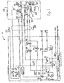
- the startup sequence begins with turning on air pump 12. This provides a positive pressure in the printhead, reducing the concentration of flammable vapor in the printhead.
- a vacuum pump 14 is turned on to create a vacuum in the ink tank 16, waste tank 18, and the cleaner tank 20.
- the exhaust from the vacuum pump is directed to an exhaust port 22 on the exterior of the fluid system cabinet. This prevents a buildup of solvent vapors inside the fluid system cabinet. It also provides a convenient means to direct these vapors into fire safe room exhaust means.
- Cleaner fluid pump 24 is turned on to pump flush fluid from the cleaner fluid tank 20 through filter means 26 and up to the printhead 28.
- Cleaner fluid valve 30 and crossflush valve 32 are open to allow the flush fluid to be pumped though the droplet generator 34 of the printhead. With waste valve 36 open and diverter valve 38 closed, flush fluid flows from the printhead to the waste tank 18, aided by the vacuum on the waste tank 18.
- the flush fluid is then pumped to the printhead at a high enough flow rate to produce approximately 1 psi at the drop generator, with the crossflush valve 32 open. Pressurizing the drop generator 34 to this pressure causes flush fluid to weep out of the orifices of the droplet generator.
- This weeping crossflush serves to seep dried ink and other particles out of the drop generator. It also redissolves any dried ink present in the orifices.
- the flush fluid weeping out of the orifices also begins rinsing off the exterior of the orifice plate 40, associated charge plate, and the catcher 44 face. This ink flows out of the catcher 44 to the waste tank 18 through the open catcher valve 46 and waste valve 36, as a result of the vacuum on the waste tank 18.
- the diverter valve 38 is closed to prevent the used flush fluid from flowing into the ink tank 16.
- This weeping crossflush state is followed by a state having lower flow rate through the drop generator 34.
- the vacuum on the waste tank 18 is sufficient to produce a slight vacuum at the drop generator 34.
- the vacuum at the droplet generator is at a level that is too high for the fluid to be able to exit through the orifices of the drop generator. Instead, the vacuum causes air to be ingested into the drop generator up through the orifices to remove any particles on the inside of the orifice plate.
- the crossflush valve 32 is closed and the cleaner pump 24 is servo-controlled to raise the flush fluid pressure in the drop generator to the necessary pressure, for example, 7.5 psi, forming jets of the flush fluid out of the orifices.
- the ink pressure is rising to the desired pressure, for example, 7.5 psi, the rapid flow of ink out of the orifices pulls any fluid out of the gap between the orifice plate and the charge plate.
- ink pump 50 is turned on to pump ink from the ink tank 16, through the filter 52, and up to the printhead 28 via umbilical 54.
- the ink pump 50 is driven to match the output from the cleaner fluid pump 48. This can be done by energizing both pumps to equal voltages, creating a printhead pressure of 7.5 psi.
- the ink supply valve 64 is now opened, the cleaner fluid valve 30 closed, and the cleaner fluid pump is turned off.
- Ink now replaces the flush fluid as the fluid being jetted from the orifices of the drop generator. This transition from flush fluid to ink, while fluid is being jetted, occurs with minimal disturbance to the jets.
- the waste valve 36 is closed and the diverter valve 38 opened to direct ink from the catcher 44 back to the ink tank 16.
- the ink heater 56 is energized, increasing the ink temperature 30° F over the ambient temperature. This causes the solvent to evaporate rapidly from the jetted ink. The solvent vapors condense on the relatively cool charge plate and catcher face. The solvent condensate dissolves any remaining ink from the face of the printhead and the catcher face. This condensate is pulled into the catcher throat and flows to the waste tank 18, as a result of the vacuum on that tank.
- the ink heater 56 is turned off, allowing the ink to cool back to ambient temperature.
- a heater 58 associated with the catcher 44, and located under the charge plate can be used to raise the temperature of the face of the charge plate, which removes any condensate from the face or the charge plate and catcher.
- a separate heater 60, associated with the eyelid 62, may be used to eliminate condensate on the eyelid as well.
Landscapes
- Ink Jet (AREA)
- Particle Formation And Scattering Control In Inkjet Printers (AREA)
Applications Claiming Priority (2)
| Application Number | Priority Date | Filing Date | Title |
|---|---|---|---|
| US264736 | 1994-06-23 | ||
| US10/264,736 US6848767B2 (en) | 2002-10-04 | 2002-10-04 | Automatic startup for a solvent ink printing system |
Publications (2)
| Publication Number | Publication Date |
|---|---|
| EP1405726A1 true EP1405726A1 (de) | 2004-04-07 |
| EP1405726B1 EP1405726B1 (de) | 2008-04-23 |
Family
ID=31993582
Family Applications (1)
| Application Number | Title | Priority Date | Filing Date |
|---|---|---|---|
| EP03256233A Expired - Lifetime EP1405726B1 (de) | 2002-10-04 | 2003-10-02 | Automatischer Anlauf des Druckersystems mit Tinte auf Lösungsmittelbasis |
Country Status (4)
| Country | Link |
|---|---|
| US (2) | US6848767B2 (de) |
| EP (1) | EP1405726B1 (de) |
| JP (1) | JP4331560B2 (de) |
| DE (1) | DE60320499T2 (de) |
Cited By (1)
| Publication number | Priority date | Publication date | Assignee | Title |
|---|---|---|---|---|
| CN111204143A (zh) * | 2020-03-13 | 2020-05-29 | 渭南科赛机电设备有限责任公司 | 一种电子轴凹版印刷机一键开机的印刷方法 |
Families Citing this family (15)
| Publication number | Priority date | Publication date | Assignee | Title |
|---|---|---|---|---|
| US6848767B2 (en) * | 2002-10-04 | 2005-02-01 | Eastman Kodak Company | Automatic startup for a solvent ink printing system |
| US7213902B2 (en) * | 2004-05-05 | 2007-05-08 | Eastman Kodak Company | Method of shutting down a continuous ink jet printer for maintaining positive pressure at the printhead |
| US7090326B2 (en) * | 2004-05-05 | 2006-08-15 | Eastman Kodak Company | Automatic startup sequence for the solvent ink printing system |
| US7695098B2 (en) * | 2005-10-11 | 2010-04-13 | Silverbrook Research Pty Ltd | Printhead maintenance system comprising disposable sheet feed |
| US8921290B2 (en) | 2006-06-06 | 2014-12-30 | Exxonmobil Research And Engineering Company | Gear oil compositions |
| US20080024532A1 (en) * | 2006-07-26 | 2008-01-31 | Si-Kyoung Kim | Methods and apparatus for inkjet printing system maintenance |
| US7955462B2 (en) * | 2007-05-25 | 2011-06-07 | Robert Tubbs | Method for accommodating the use of chemicals that contain low amounts of VOC in an existing device where chemicals that contained high levels of VOC had previously been used and resultant product |
| US8613501B2 (en) * | 2007-10-12 | 2013-12-24 | Videojet Technologies Inc. | Ink supply system |
| FR2924379B1 (fr) * | 2007-11-29 | 2011-04-22 | Imaje Sa | Tete d'impression a jet d'encre a nettoyage automatise au demarrage d'impression |
| FR2955801B1 (fr) | 2010-02-01 | 2012-04-13 | Markem Imaje | Dispositif formant pupitre d'imprimante a jet d'encre continu, a concentrations de vapeur de solvant a l'interieur et autour du pupitre diminuees |
| US8670235B2 (en) | 2011-03-14 | 2014-03-11 | Xerox Corporation | Removal of vapor and ultrafine particles from printing device |
| EP2913190B1 (de) | 2014-02-28 | 2020-10-07 | HP Scitex Ltd | Druckkopfdüsenwartung |
| US10179454B2 (en) * | 2017-04-25 | 2019-01-15 | Rf Printing Technologies | Inkjet printing system with non-contact cleaning station |
| US10946645B2 (en) | 2017-05-01 | 2021-03-16 | Hewlett-Packard Development Company, L.P. | Pause start-up routine of imaging device |
| US10632757B1 (en) * | 2018-12-10 | 2020-04-28 | Xerox Corporation | System and method for attenuating the drying of ink from a printhead during idle periods |
Citations (3)
| Publication number | Priority date | Publication date | Assignee | Title |
|---|---|---|---|---|
| US4050078A (en) * | 1974-12-09 | 1977-09-20 | Ricoh Company, Ltd. | Automatic nozzle cleaning system for ink ejection printer |
| US4600928A (en) * | 1985-04-12 | 1986-07-15 | Eastman Kodak Company | Ink jet printing apparatus having ultrasonic print head cleaning system |
| DE3607237A1 (de) * | 1985-03-13 | 1986-09-18 | Contraves Gmbh, 8013 Haar | Tintenstrahldrucker |
Family Cites Families (8)
| Publication number | Priority date | Publication date | Assignee | Title |
|---|---|---|---|---|
| US3891121A (en) * | 1972-08-04 | 1975-06-24 | Mead Corp | Method of operating a drop generator that includes the step of pre-pressurizing the liquid manifold |
| US4622562A (en) * | 1985-04-12 | 1986-11-11 | Eastman Kodak Company | Ink jet printhead multi-component heating |
| GB2236712B (en) * | 1989-10-11 | 1993-06-30 | Linx Printing Tech | Ink jet printer head flushing |
| US5757396A (en) * | 1994-06-30 | 1998-05-26 | Compaq Computer Corporation | Ink jet printhead having an ultrasonic maintenance system incorporated therein and an associated method of maintaining an ink jet printhead by purging foreign matter therefrom |
| GB9719705D0 (en) * | 1997-09-16 | 1997-11-19 | Domino Printing Sciences Plc | Ink jet printer |
| US6273103B1 (en) * | 1998-12-14 | 2001-08-14 | Scitex Digital Printing, Inc. | Printhead flush and cleaning system and method |
| US6435637B1 (en) * | 1999-10-29 | 2002-08-20 | Scitex Digital Printing, Inc. | Fluid and vacuum control in an ink jet printing system |
| US6848767B2 (en) * | 2002-10-04 | 2005-02-01 | Eastman Kodak Company | Automatic startup for a solvent ink printing system |
-
2002
- 2002-10-04 US US10/264,736 patent/US6848767B2/en not_active Expired - Fee Related
-
2003
- 2003-10-02 EP EP03256233A patent/EP1405726B1/de not_active Expired - Lifetime
- 2003-10-02 DE DE60320499T patent/DE60320499T2/de not_active Expired - Lifetime
- 2003-10-06 JP JP2003346706A patent/JP4331560B2/ja not_active Expired - Fee Related
-
2004
- 2004-12-07 US US11/006,442 patent/US7055931B2/en not_active Expired - Fee Related
Patent Citations (3)
| Publication number | Priority date | Publication date | Assignee | Title |
|---|---|---|---|---|
| US4050078A (en) * | 1974-12-09 | 1977-09-20 | Ricoh Company, Ltd. | Automatic nozzle cleaning system for ink ejection printer |
| DE3607237A1 (de) * | 1985-03-13 | 1986-09-18 | Contraves Gmbh, 8013 Haar | Tintenstrahldrucker |
| US4600928A (en) * | 1985-04-12 | 1986-07-15 | Eastman Kodak Company | Ink jet printing apparatus having ultrasonic print head cleaning system |
Cited By (1)
| Publication number | Priority date | Publication date | Assignee | Title |
|---|---|---|---|---|
| CN111204143A (zh) * | 2020-03-13 | 2020-05-29 | 渭南科赛机电设备有限责任公司 | 一种电子轴凹版印刷机一键开机的印刷方法 |
Also Published As
| Publication number | Publication date |
|---|---|
| US6848767B2 (en) | 2005-02-01 |
| JP4331560B2 (ja) | 2009-09-16 |
| US7055931B2 (en) | 2006-06-06 |
| DE60320499D1 (de) | 2008-06-05 |
| US20040066427A1 (en) | 2004-04-08 |
| JP2004276587A (ja) | 2004-10-07 |
| EP1405726B1 (de) | 2008-04-23 |
| DE60320499T2 (de) | 2009-05-20 |
| US20050083368A1 (en) | 2005-04-21 |
Similar Documents
| Publication | Publication Date | Title |
|---|---|---|
| US6869160B2 (en) | Purge shutdown for a solvent ink printing system | |
| US6848767B2 (en) | Automatic startup for a solvent ink printing system | |
| JP4270817B2 (ja) | クリーニング機能付きコンティニュアス・インクジェット印刷装置 | |
| US7213902B2 (en) | Method of shutting down a continuous ink jet printer for maintaining positive pressure at the printhead | |
| JP5451103B2 (ja) | インクジェット記録装置および記録ヘッドの回復処理方法 | |
| US6183058B1 (en) | Self-cleaning ink jet printer system with reverse fluid flow and method of assembling the printer system | |
| JPH03193460A (ja) | インキジェットプリンタのプリントヘッドを洗浄する方法 | |
| CN100478182C (zh) | 连续喷墨打印机的清洁系统、自清洁打印头和清洁方法 | |
| CN100427315C (zh) | 喷墨式记录装置 | |
| EP1435293B1 (de) | Automatische Inbetriebnahme eines Tintendrucksystems für lösungsmittelhaltige Tinte | |
| JP2004223829A (ja) | インクジェット記録装置 | |
| US6679590B2 (en) | Shutdown for an ink jet printer | |
| JP2004209985A5 (de) | ||
| WO1999062717A1 (en) | Ink jet printer and method of operation | |
| JP2002096486A (ja) | インクジェット・プリントヘッドの整備方法 | |
| JP2007230097A (ja) | インクジェット方式画像形成装置 | |
| JP6019562B2 (ja) | 液体噴射装置 | |
| US20260109152A1 (en) | Printhead system with nozzle rejuvenation system | |
| JPH08310005A (ja) | インクジェットプリンタ | |
| JP4311720B2 (ja) | インクジェット方式画像形成装置及びインク供給方法 | |
| JP2000108363A (ja) | インクジェットプリンタ | |
| CN120569296A (zh) | 用于清洁自清洁头的计算机实现的方法 | |
| JPS61233549A (ja) | インクジエツトプリンタのインク供給装置 | |
| JPS60101055A (ja) | インクジエツトプリンタの吐出維持方法 |
Legal Events
| Date | Code | Title | Description |
|---|---|---|---|
| PUAI | Public reference made under article 153(3) epc to a published international application that has entered the european phase |
Free format text: ORIGINAL CODE: 0009012 |
|
| AK | Designated contracting states |
Kind code of ref document: A1 Designated state(s): AT BE BG CH CY CZ DE DK EE ES FI FR GB GR HU IE IT LI LU MC NL PT RO SE SI SK TR |
|
| AX | Request for extension of the european patent |
Extension state: AL LT LV MK |
|
| RAP1 | Party data changed (applicant data changed or rights of an application transferred) |
Owner name: EASTMAN KODAK COMPANY |
|
| 17P | Request for examination filed |
Effective date: 20040911 |
|
| AKX | Designation fees paid |
Designated state(s): DE FR GB |
|
| 17Q | First examination report despatched |
Effective date: 20061220 |
|
| GRAP | Despatch of communication of intention to grant a patent |
Free format text: ORIGINAL CODE: EPIDOSNIGR1 |
|
| GRAS | Grant fee paid |
Free format text: ORIGINAL CODE: EPIDOSNIGR3 |
|
| GRAA | (expected) grant |
Free format text: ORIGINAL CODE: 0009210 |
|
| AK | Designated contracting states |
Kind code of ref document: B1 Designated state(s): DE FR GB |
|
| REG | Reference to a national code |
Ref country code: GB Ref legal event code: FG4D |
|
| REF | Corresponds to: |
Ref document number: 60320499 Country of ref document: DE Date of ref document: 20080605 Kind code of ref document: P |
|
| ET | Fr: translation filed | ||
| PLBE | No opposition filed within time limit |
Free format text: ORIGINAL CODE: 0009261 |
|
| STAA | Information on the status of an ep patent application or granted ep patent |
Free format text: STATUS: NO OPPOSITION FILED WITHIN TIME LIMIT |
|
| 26N | No opposition filed |
Effective date: 20090126 |
|
| PGFP | Annual fee paid to national office [announced via postgrant information from national office to epo] |
Ref country code: GB Payment date: 20120925 Year of fee payment: 10 |
|
| PGFP | Annual fee paid to national office [announced via postgrant information from national office to epo] |
Ref country code: DE Payment date: 20121031 Year of fee payment: 10 Ref country code: FR Payment date: 20121010 Year of fee payment: 10 |
|
| GBPC | Gb: european patent ceased through non-payment of renewal fee |
Effective date: 20131002 |
|
| PG25 | Lapsed in a contracting state [announced via postgrant information from national office to epo] |
Ref country code: GB Free format text: LAPSE BECAUSE OF NON-PAYMENT OF DUE FEES Effective date: 20131002 |
|
| REG | Reference to a national code |
Ref country code: DE Ref legal event code: R119 Ref document number: 60320499 Country of ref document: DE Effective date: 20140501 |
|
| REG | Reference to a national code |
Ref country code: FR Ref legal event code: ST Effective date: 20140630 |
|
| PG25 | Lapsed in a contracting state [announced via postgrant information from national office to epo] |
Ref country code: DE Free format text: LAPSE BECAUSE OF NON-PAYMENT OF DUE FEES Effective date: 20140501 Ref country code: FR Free format text: LAPSE BECAUSE OF NON-PAYMENT OF DUE FEES Effective date: 20131031 |