EP1405939A1 - Procédé et dispositif pour réensoupler une nappe de fils - Google Patents
Procédé et dispositif pour réensoupler une nappe de fils Download PDFInfo
- Publication number
- EP1405939A1 EP1405939A1 EP02022407A EP02022407A EP1405939A1 EP 1405939 A1 EP1405939 A1 EP 1405939A1 EP 02022407 A EP02022407 A EP 02022407A EP 02022407 A EP02022407 A EP 02022407A EP 1405939 A1 EP1405939 A1 EP 1405939A1
- Authority
- EP
- European Patent Office
- Prior art keywords
- warping
- warping drum
- bäumgestell
- support
- braking
- Prior art date
- Legal status (The legal status is an assumption and is not a legal conclusion. Google has not performed a legal analysis and makes no representation as to the accuracy of the status listed.)
- Withdrawn
Links
Images


Classifications
-
- D—TEXTILES; PAPER
- D02—YARNS; MECHANICAL FINISHING OF YARNS OR ROPES; WARPING OR BEAMING
- D02H—WARPING, BEAMING OR LEASING
- D02H5/00—Beaming machines
-
- D—TEXTILES; PAPER
- D02—YARNS; MECHANICAL FINISHING OF YARNS OR ROPES; WARPING OR BEAMING
- D02H—WARPING, BEAMING OR LEASING
- D02H13/00—Details of machines of the preceding groups
- D02H13/12—Variable-speed driving mechanisms
- D02H13/14—Variable-speed driving mechanisms controlled automatically by tension in the warp
-
- D—TEXTILES; PAPER
- D02—YARNS; MECHANICAL FINISHING OF YARNS OR ROPES; WARPING OR BEAMING
- D02H—WARPING, BEAMING OR LEASING
- D02H13/00—Details of machines of the preceding groups
- D02H13/22—Tensioning devices
- D02H13/26—Tensioning devices for threads in warp form
Definitions
- the invention relates to a method for rebuilding a group of threads according to the preamble of claim 1.
- the previous sections are wound on the warping drum Shurb selected for the production of the warp together on the Kettbaum wound up. This is only with the cone warping machine an axis-parallel relative displacement between warping drum and Kettbaum possible, because the relative position of the thread association with changed decreasing winding diameter.
- An additional advantage can be achieved via the support when done via a force measuring device, which is one of the pulling force generated in the group of threads corresponding measurement signal and if the braking force on the warping drum, preferably with the aid of the measuring signal is regulated.
- a force measuring device which is one of the pulling force generated in the group of threads corresponding measurement signal and if the braking force on the warping drum, preferably with the aid of the measuring signal is regulated.
- a force measuring device which is one of the pulling force generated in the group of threads corresponding measurement signal and if the braking force on the warping drum, preferably with the aid of the measuring signal is regulated.
- a force measuring device which is one of the pulling force generated in the group of threads corresponding measurement signal and if the braking force on the warping drum, preferably with the aid of the measuring signal is regulated.
- the Ceiillard Republic a measuring roller used, which of the yarn sheet is partially entwined.
- the effective wrap angle is variable.
- the rebuilding takes place from the apex line of the warping drum to the apex line of the warp beam, without deflecting roller.
- reshaping presupposes that the individual warp band sections be wound up over the foot line of the warping drum.
- By omitting the guide roller can eliminate another disturbance which could affect the quality of the warp beam.
- Very high tensile forces can be used when braking the warping drum with at least two, preferably at least four brake discs are made, each with at least two Brake calipers is equipped and if the brake calipers in dependence sequentially activated sequentially by the required braking power or disabled. In the high load range spread while the braking forces on all active discs, which also the life of the discs is extended.
- the invention also relates to a device for rearranging a group of threads, which has the features in claim 6.
- the support takes place advantageously at least two, preferably with rolling bearings provided support bearings. In this way, the friction is like that kept as low as possible. In certain applications, however, would be also the use of plain bearings conceivable.
- a particularly advantageous support is obtained when the distance between the at least two support bearings the same size or larger is the maximum usable width (cylindrical plus conical section) the warping drum. In this way, unwanted additional forces reliably avoided.
- the support bearings can be used with a force measuring device for measuring the corresponding to a certain compressive force tensile force in the yarn sheet be provided.
- Pressure-responsive force sensors are available as standard for different measuring ranges.
- the force measuring device is preferably in operative connection with the braking device on the warping drum to the tensile force in the yarn sheet to regulate. But it would also be conceivable a mere measurement and Record the tensile forces to record a log for each warp beam to be able to create his condition.
- the support on the mounted on rails warping drum frame takes place advantageously approximately on the horizontal plane of the warping drum axis or above. This creates a particularly advantageous Of forces.
- the support can also be used with an emergency stop device to interrupt the relative displacement between Shurgestell and Bäumgestell provided when exceeding a predetermined resistance his.
- the Braking device on the warping drum at least four discs each having at least two brake calipers is. Although a higher braking force could also be achieved by increasing the diameter the existing brake discs are achieved. A Such enlargement is not arbitrary for reasons of space possible. The arrangement of additional brake discs could depending on the application also on conventional devices for rebuilding a Yarn be beneficial.
- each two brake discs are arranged and if respectively the outer Brake disks detachable from the outside on the warping drum axis are attached. This construction allows an existing one Later warp machine for use with higher warp tension upgrade.
- the brake caliper on the brake disc preferably diametrically opposite each other and if the Brake caliper pairs of adjacent brake discs offset angularly are arranged to each other. This results in a very small width and good accessibility of the brake calipers.
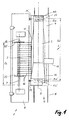
- the device consists for turning essentially from a cone warping machine 1 and a Baking machine 2.
- the cone warping machine has a warping drum 5, which has a cone portion 19 and in a Schrgestell 4 is rotatably mounted.
- the Schrgestell 4 is on the Foundation 30 mounted on rails 8 and can in the direction of the B Warping drum axis 9 are moved.
- the braking device preferably consists of a total four brake discs 15a, 15b, 15a ', 15b', each of which at least has two brake calipers.
- the warp beam 7 is mounted in a Bäumgestell 6, but in the Contrary to the Schwarzrgestell firmly anchored on the foundation 30.
- the trees 20, 20 ' can the respective useful width of the yarn sheet 3 are adapted, with a maximum useful width D2 possible is.
- the support bearings are located 14 approximately on the horizontal plane of the warping drum axis 9 or slightly above it.
- the Umbaum takes place from the crest line 34 of the Warping drum 5 on the apex line 35 of the warp beam 7. It can optionally also a deflection roller 12 are used.
- a tilting of the Schwarzrgestells 4 no longer possible without additional weight load, because the overturning moment is absorbed by the support bearings.
- the warp beam axis 10 and the warping drum axis. 9 be aligned exactly parallel to each other.
- each bearing is connected by means of a connection plate 24 on the Schwarzergestell 4 bolted.
- the actual support takes place on a rolling bearing, for example, on a needle bearing 21, the outer race rolls on a support bar 22 which is fixed to the Bäumgestell 4.
- the delivery of the rolling bearing is adjustable via a Adjustment device 23.
- the pressure force acting on the support bearing 14 can via a force measuring device 11 in a known manner be determined. In the known geometry between the support bearings and the group of threads can be on this measurement signal the effective Measure the tension in the yarn sheet permanently.
- an emergency stop device 17 may be provided, which has a resistance transverse to the feed direction the Schrgestells 4 reacts and the the feed or interrupts the restructuring process.
- the support bearing 14 surrounded by a housing 25, relative to the connection plate 24th about a pivot axis 16 in the direction of arrow C is pivotable.
- the housing is doing by bilaterally arranged springs 40 in one kept neutral.
- this middle layer is one of the connection plate 24 associated switching cam 38 in the recess of a Shift gate 39, which is associated with the housing 25.
- the housing 25 also serves to protect the support bearings from contamination.
- the housing forms together with the connection plate 24 a kind of barrier, which theoretically possible access locked to the gap.
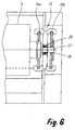
- FIGS. 5 and 6 show details of the braking devices 13 on the sides of the warping drum 5. This is at both ends of the Warp drum bearings 26 stored.
- a second outer brake disc 15b is arranged in each case. The latter can be subsequently mounted on a bearing journal 27, with the help of a clamping sleeve 28th
- Each brake disk is assigned a brake caliper bearing 31a or 31b, which two preferably diametrically opposite each other Brake calipers 32 can record.
- the brake caliper bearings of adjacent brake discs are angular staggered to each other to minimize To allow width.
- Kettbaumrea depending on the yarn quality Kettbaumrea be driven to about 30'000 N.
- two brake discs with two brake calipers suffice.
- the additional discs become.
- the specified maximum warp rates are engine outputs up to approx. 60 kW required.
Landscapes
- Engineering & Computer Science (AREA)
- Textile Engineering (AREA)
- Warping, Beaming, Or Leasing (AREA)
Priority Applications (2)
| Application Number | Priority Date | Filing Date | Title |
|---|---|---|---|
| EP02022407A EP1405939A1 (fr) | 2002-10-04 | 2002-10-04 | Procédé et dispositif pour réensoupler une nappe de fils |
| US10/646,924 US20040083587A1 (en) | 2002-10-04 | 2003-08-25 | Method and apparatus for the rewinding of a thread group |
Applications Claiming Priority (1)
| Application Number | Priority Date | Filing Date | Title |
|---|---|---|---|
| EP02022407A EP1405939A1 (fr) | 2002-10-04 | 2002-10-04 | Procédé et dispositif pour réensoupler une nappe de fils |
Publications (1)
| Publication Number | Publication Date |
|---|---|
| EP1405939A1 true EP1405939A1 (fr) | 2004-04-07 |
Family
ID=31985055
Family Applications (1)
| Application Number | Title | Priority Date | Filing Date |
|---|---|---|---|
| EP02022407A Withdrawn EP1405939A1 (fr) | 2002-10-04 | 2002-10-04 | Procédé et dispositif pour réensoupler une nappe de fils |
Country Status (2)
| Country | Link |
|---|---|
| US (1) | US20040083587A1 (fr) |
| EP (1) | EP1405939A1 (fr) |
Families Citing this family (1)
| Publication number | Priority date | Publication date | Assignee | Title |
|---|---|---|---|---|
| CN108861857A (zh) * | 2018-07-31 | 2018-11-23 | 江苏田园新材料股份有限公司 | 弹性丝整经张力控制架 |
Citations (3)
| Publication number | Priority date | Publication date | Assignee | Title |
|---|---|---|---|---|
| DE2510517A1 (de) * | 1975-03-11 | 1976-09-16 | Hacoba Textilmaschinen | Konusschaermaschine |
| DE4304955A1 (de) * | 1993-02-18 | 1994-08-25 | Mayer Textilmaschf | Verfahren zum Umbäumen von Fäden auf einen Kettbaum und zugehörige Bäummaschine |
| EP0965668A2 (fr) * | 1998-06-17 | 1999-12-22 | Benninger AG | Procédé et dispositif pour transférer une nappe enroulée de fils sur une ensouple |
Family Cites Families (2)
| Publication number | Priority date | Publication date | Assignee | Title |
|---|---|---|---|---|
| JPS5199143A (fr) * | 1975-02-27 | 1976-09-01 | Baba Sangyo Kikai | |
| EP0659914B1 (fr) * | 1993-12-22 | 1999-03-24 | Benninger AG | Procédé et dispositif pour l'enroulage de bandes d'ourdissage |
-
2002
- 2002-10-04 EP EP02022407A patent/EP1405939A1/fr not_active Withdrawn
-
2003
- 2003-08-25 US US10/646,924 patent/US20040083587A1/en not_active Abandoned
Patent Citations (3)
| Publication number | Priority date | Publication date | Assignee | Title |
|---|---|---|---|---|
| DE2510517A1 (de) * | 1975-03-11 | 1976-09-16 | Hacoba Textilmaschinen | Konusschaermaschine |
| DE4304955A1 (de) * | 1993-02-18 | 1994-08-25 | Mayer Textilmaschf | Verfahren zum Umbäumen von Fäden auf einen Kettbaum und zugehörige Bäummaschine |
| EP0965668A2 (fr) * | 1998-06-17 | 1999-12-22 | Benninger AG | Procédé et dispositif pour transférer une nappe enroulée de fils sur une ensouple |
Also Published As
| Publication number | Publication date |
|---|---|
| US20040083587A1 (en) | 2004-05-06 |
Similar Documents
| Publication | Publication Date | Title |
|---|---|---|
| DE19620670C2 (de) | Vorrichtung zum Aufwickeln einer Wirkwarenbahn | |
| DE102007002218A1 (de) | Wickelvorrichtung zum Wickeln von Bändern | |
| DE102013002022B4 (de) | Vorrichtung zum Wickeln eines strangförmigen Wickelguts und Verfahren dazu | |
| EP0921085A2 (fr) | Procédé et machine d'enroulage pour enrouler en continu une bande de matière | |
| DE102013002023B4 (de) | Vorrichtung und Verfahren zum Wickeln eines strangförmigen Wickelguts | |
| DE1435219B2 (de) | Klöppel für Flechtmaschinen, insbesondere Schlauchumflechtungsmaschinen | |
| EP2261164A2 (fr) | Dispositif de guidage avec régulation de mouvement rectiligne et centré pour grue équipée de galets de roulement sur chemin de roulement avec rails | |
| DE1234499B (de) | Einrichtung zur Lagerung und/oder zum Antrieb von Trommeln u. dgl. | |
| DE2059283A1 (de) | Bandfuehrungs- und -dehnvorrichtung | |
| EP1405939A1 (fr) | Procédé et dispositif pour réensoupler une nappe de fils | |
| DE2224875C3 (de) | Vorrichtung zum Belasten und Trennen der Walzen eines der Bearbeitung von Bahnen, insbesondere von Papierbahnen, dienenden Walzensatzes | |
| EP0933320B1 (fr) | Bobineuse | |
| DE3510490A1 (de) | Ueberlastsicherung fuer hebezeuge oder dergleichen | |
| DE9115481U1 (de) | Wickelmaschine zum Aufwickeln einer Bahn, insbesondere einer Papierbahn | |
| EP1960298A1 (fr) | Bras danseur pour une tension de traction constante | |
| EP0085390B1 (fr) | Procédé pour envelopper une pile d'objets à l'aide de plusieurs enroulements d'une bande de matériau extensible | |
| DE2502213A1 (de) | Vorrichtung zum mechanischen ziehen von kabeln | |
| EP1947042B1 (fr) | Machine d'enroulement | |
| EP4103329A1 (fr) | Bielle de réaction destinée à intercepter un couple d'entraînement et ensemble rouleaux muni d'une bielle de réaction | |
| DE3437455A1 (de) | Vorrichtung zum verhindern eines wicklers im falle eines bahnrisses | |
| DE2130020A1 (de) | Baeummaschine | |
| CH660720A5 (de) | Fadenbremsvorrichtung. | |
| EP2019060B1 (fr) | Dispositif d'enroulement et procédé d'enroulement de bandes de matière fibreuse dans un dispositif d'enroulement | |
| DE8708849U1 (de) | Doppeltragwalzen-Wickelmaschine | |
| DE102007051526B3 (de) | Einrichtung zum Abziehen der Warenbahn an einer Webmaschine und Webmaschine mit einer derartigen Einrichtung |
Legal Events
| Date | Code | Title | Description |
|---|---|---|---|
| PUAI | Public reference made under article 153(3) epc to a published international application that has entered the european phase |
Free format text: ORIGINAL CODE: 0009012 |
|
| AK | Designated contracting states |
Kind code of ref document: A1 Designated state(s): AT BE BG CH CY CZ DE DK EE ES FI FR GB GR IE IT LI LU MC NL PT SE SK TR |
|
| AX | Request for extension of the european patent |
Extension state: AL LT LV MK RO SI |
|
| AKX | Designation fees paid | ||
| REG | Reference to a national code |
Ref country code: DE Ref legal event code: 8566 |
|
| STAA | Information on the status of an ep patent application or granted ep patent |
Free format text: STATUS: THE APPLICATION IS DEEMED TO BE WITHDRAWN |
|
| 18D | Application deemed to be withdrawn |
Effective date: 20041008 |