EP1405943A2 - Métier pour la fabrication de tissus de gaze - Google Patents
Métier pour la fabrication de tissus de gaze Download PDFInfo
- Publication number
- EP1405943A2 EP1405943A2 EP03405651A EP03405651A EP1405943A2 EP 1405943 A2 EP1405943 A2 EP 1405943A2 EP 03405651 A EP03405651 A EP 03405651A EP 03405651 A EP03405651 A EP 03405651A EP 1405943 A2 EP1405943 A2 EP 1405943A2
- Authority
- EP
- European Patent Office
- Prior art keywords
- leno
- nozzles
- shed
- cleaning device
- upright
- Prior art date
- Legal status (The legal status is an assumption and is not a legal conclusion. Google has not performed a legal analysis and makes no representation as to the accuracy of the status listed.)
- Granted
Links
Images


Classifications
-
- D—TEXTILES; PAPER
- D03—WEAVING
- D03J—AUXILIARY WEAVING APPARATUS; WEAVERS' TOOLS; SHUTTLES
- D03J1/00—Auxiliary apparatus combined with or associated with looms
- D03J1/002—Climatic conditioning or removing lint or dust
-
- D—TEXTILES; PAPER
- D03—WEAVING
- D03C—SHEDDING MECHANISMS; PATTERN CARDS OR CHAINS; PUNCHING OF CARDS; DESIGNING PATTERNS
- D03C7/00—Leno or similar shedding mechanisms
Definitions
- the invention relates to a weaving machine for producing leno fabrics according to the preamble of claim 1 and a method for cleaning a Loom according to the preamble of claim 7.
- Warp threads cross with each new specialist training, i.e. the lower warp threads come to the top and the upper ones below.
- the warp threads By crossing the warp threads during shedding Larger accumulations of fiber fly in the shed largely avoided.
- the object of the invention is to produce a weaving machine To provide leno fabrics which are used to clean the Turning device and the shed does not have to be stopped.
- a Another object of the invention is a method for cleaning a To provide weaving machines for the production of leno fabrics, by means of which contamination of the leno device and the shed can be removed effectively.
- this object is defined by that in claim 1 Loom solved and by the method defined in claim 7.
- the weaving machine according to the invention for producing leno fabrics comprises a leno device with leno elements to form a Shed.
- the loom includes one in the loom Integrated cleaning device for removing impurities in the Area of the lathe device and / or the shed.
- the weaving machine is known Way equipped with a reed, and include the leno elements Guide elements and a deflection element for upright threads as well Leno thread guide elements.
- the integrated cleaning device one or more nozzles, by means of which in the area between the upright and leno threads, especially in the back of the shed, essentially one horizontal compressed air flow transverse to the direction of the upright and Leno threads can be produced.
- the integrated cleaning device comprises at least one nozzle, which is arranged between the reed and the leno thread guide elements, and by means of which one is directed downwards through the shed from above Compressed air flow or suction air flow can be generated.
- the integrated cleaning device at least one nozzle, which in the lower area of the leno elements is arranged, and by means of which a directed against the leno elements Compressed air flow or suction air flow can be generated.
- the cleaning device includes two Compressed air fed nozzles between the reed and the Leno thread guide elements are arranged, and from above against the shed are directed, with one of the two nozzles between the reed and the upright thread guide elements is arranged and the other nozzle between the main thread and the leno thread guide elements.
- a Another embodiment variant comprises at least the cleaning device two nozzles, one of which is a substantially horizontal one Has jet direction and a nozzle a substantially vertical Beam direction.
- the integrated cleaning device preferably comprises at least one Nozzle that is movably arranged in the longitudinal direction of the reed.
- the integrated cleaning device preferably comprises at least one Nozzle, which is arranged as a stationary slot nozzle with horizontal Slot arrangement is executed.
- the integrated comprises Cleaning device one or more stationary suction nozzles and / or a suction channel that runs transversely below the shed Direction of the upright and leno threads are arranged.
- the deflection element in the leno device is preferably the Loom pressurized with compressed air and includes nozzles, by means of which essentially in the area between the upright and leno threads horizontal compressed air flow transverse to the direction of the upright and Leno threads can be produced.
- the weaving machine comprises a controller to operate the compressed air and / or suction nozzles integrated cleaning device and to control the nozzles of the to activate the integrated cleaning device.
- the Control Preferably, the Control, the nozzles periodically and / or cyclically and / or in succession and / or to activate if necessary.
- the weaving machine can preferably be used in a weaving mill, which Weaving mill is equipped with one or more traveling cleaners, the Control is suitable, the integrated cleaning device Activate the weaving machine in coordination with the cleaning agents.
- the inventive method for cleaning a weaving machine Production of leno fabrics, which weaving machine one Turner device with leno elements to form a shed is characterized by the fact that impurities in the area of Lathe device and / or the shed by means of a in the loom integrated cleaning device can be removed.
- the integrated Cleaning device of the weaving machine via a control in the Weaving machine activated.
- the loom is in one Weaving used, which weaving with one or more Hiking cleaners are equipped with the integrated cleaning device the weaving machine is activated in coordination with the traveling cleaners.
- the internal cleaning device from the Shed-conveyed dirt removed by traveling cleaners.
- the integrated cleaning device includes several nozzles, by means of which in the area between the upright and leno threads, especially in the back of the shed, essentially one horizontal compressed air flow transverse to the direction of the upright and Leno threads is produced.
- the nozzles are periodic and / or cyclically and / or successively and / or if necessary with compressed air be charged.
- the said nozzles preferably cooperate at least one substantially vertically oriented nozzle and / or with at least one essentially horizontal against the direction of travel the nozzle aligned with the upright and leno threads.
- a nozzle arrangement by means of which between the upright and a substantially horizontal compressed air flow across the leno threads to the direction of the upright and leno threads can be generated and by means of what impurities, in particular also fiber fly accumulations, the in the area of the shed between the upright and leno threads included, can be removed.
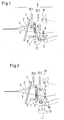
- Fig. 1 shows a first embodiment of a weaving machine for Manufacture of leno fabrics according to the present invention.
- the weaving machine comprises a lathe device and a Advised 2 to strike a registered weft thread.
- the Rotary device comprises guide elements 7 and a deflection element 5, 5 ' for upright threads 4 and leno thread guide elements 8, 8 'to form a Shed 6 and for making the leno weave.
- the shed 6 includes in the following not only that between reed 2 and stop edge Front compartment, but the entire area between the standing and Leno threads 3, 3 ', 4, which are raised at different levels and / or include lowered upright and leno threads.
- the Stand thread guide elements 7 are in the embodiment as a needle bar with upright lamellas, which are provided with eyelets at the free end.
- the loom includes an integrated loom Cleaning device with several nozzles 10.2, 10.2, 11, 11 '.
- the first Embodiment are between the reed 2 and the Leno thread guide elements 8, 8 'two nozzles 10.1, fed with compressed air, 10.2 arranged, which are directed from above against the shed 6, wherein one of the two nozzles 10.1 between the reed 2 and the Thread guide elements 7 is arranged and the other nozzle 10.2 between the upright thread and the leno thread guide elements 7, 8, 8 '.
- the two nozzles 10.1, 10.2 one can pass through the shed 6 from above downward compressed air flow 16.1, 16.2 are generated.
- a Another nozzle 11 is in the lower region of the upright thread guide elements 7 arranged by means of which against the upright thread guide elements 7 and / or the deflection element 5 directed compressed air flow 17 are generated can.
- the latter is preferably directed essentially horizontally.
- the deflection element 5 ' is offset from the Thread guide elements 7 arranged.
- the integrated cleaning device comprises a suction nozzle 13 which below the shed 6 and preferably in the area of Deflection element 5 is arranged.
- the suction nozzle 13 By means of the suction nozzle 13 one of Generated by the shed 6 downward suction air flow 19 become.
- the suction air flow supports 19 the cleaning effect of the compressed air streams 16.1, 16.2 acting from above and serves to remove the blown fiber fly from the weaving machine remove.
- a single suction nozzle 13 can advantageously a number of suction nozzles 13 and / or a suction channel are provided, which are horizontal and transverse to the direction of the upright and leno threads 3, 3 ', 4 are arranged.
- the exemplary embodiment includes the integrated cleaning device Compressed air blower 9, which is directed against the shed 6 from above Nozzles 10.1, 10.2 supplied with compressed air.
- the air blower 9 is can be moved together with the nozzles 10.1, 10.2 on a traverse 20 attached so that the nozzles parallel to the longitudinal direction of the reed 2, 2 ' can be moved.
- the sliding arrangement of the nozzles enables cleaning across the entire weaving width.
- the one in the bottom Area of the thread guide elements 7 arranged nozzle 11, by means of which one against the upright thread guide elements 7 and / or that Deflection element 5 directed compressed air flow 17 can be generated as stationary slot nozzle with horizontal slot arrangement executed. Alternatively, you can also use one in the longitudinal direction at this point of reed 2, 2 'movable nozzle 11 may be provided.
- FIG. 6 shows an enlarged section of the nozzle arrangement to that in FIG Fig. 5 shown embodiment.
- the reed is in Fig. 6 in Stop position 2 'shown.
- the position of the is also shown Thread guide elements 7 ', the deflecting element 5' and the Leno thread guide elements 8 'and the position 3', 4 'of the upright and Leno threads when the reed is in the stop position 2 '.
- a second embodiment of the present invention which is shown in Fig. 3, the orientation of the upright thread guide elements 7 compared to the first embodiment, i.e. the Attachment of the upright thread guide elements is now on top and the Eyelets of the standing needles are now arranged at the lower end.
- the second Embodiment includes three integrated cleaning device Compressed air fed nozzles 10.1-10.3, which are between the reed 2 and the Leno thread guide elements 8, 8 'arranged and from above against Shed 6 are directed, with one of the three nozzles 10.1 between the reed 2 and the thread guide elements 7 is arranged and each a nozzle 10.2, 10.3 before and after the deflecting element 5.
- nozzles 10.1-10.3 can be a downward from above through the shed 6 Compressed air flow 16.1 are generated.
- Another nozzle 11 is in the lower Area of the thread guide elements 7 arranged, by means of which a directed towards the eyelets of the upright thread guide elements 7 Compressed air stream 17 can be generated.
- the integrated cleaning device in the second Embodiment provided with a suction nozzle 13 which below the Shed 6 and preferably between the upright and Leno thread guide elements 7, 8, 8 'is arranged.
- a suction nozzle 13 By means of the suction nozzle 13 can be directed from above through the shed 6 downwards Suction air flow 19 are generated.
- the suction air flow 19 the cleaning effect of the acting from above Compressed air flow 16.1 and serves to blow the blown fiber from the Remove loom.
- a single suction nozzle 13 can advantageously a number of suction nozzles 13 and / or a suction channel are provided, which are horizontal and transverse to the direction of the standing round Leno threads 3, 3 ', 4 are arranged.
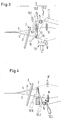
- Fig. 4 shows a third embodiment of the present invention, in which the integrated cleaning device one or more nozzles 12.1 includes seen in the direction of the upright and leno threads 3, 3 ', 4 before the thread guide elements 7 are arranged.
- the nozzles are 12.1 arranged such that the nozzles between the upright and the Leno threads an essentially horizontal stream of compressed air across Direction of the upright and leno threads can be generated.
- the nozzles 12.1 are preferably in a row between the upright and Leno threads arranged.
- the nozzles 12.1 executed as relay nozzles, the nozzles being cyclical, in the sense of a Compressed air are applied to the moving field.
- nozzle or nozzles 12.1 can accumulate fiber flights, especially larger ones Collections in the area of the shed between the standing and Leno threads are included, blown out to the selvedge and be removed.
- Fig. 4 additionally shows two variants with one second arrangement 12.2 and third arrangement 12.3 of the nozzles, by means of which is a substantially horizontal flow of compressed air across Direction of the upright and leno threads can be generated.
- the second arrangement 12.2 are the nozzles as in the basic variant of the third Embodiment in the direction of the upright and leno threads 3, 3 ', 4th seen in front of the upright thread guide elements 7 and in the third arrangement 12.3 between the reed 2 and the Standard thread guide elements 7.
- the deflecting element 5 of the leno device as part of the integrated cleaning device.
- the deflection element 5 is closed pressurized with compressed air for this purpose and includes nozzles 12.1-12.4 Removal of fiber fly from the area around the deflecting element and out the shed 6.
- the nozzle openings are of the nozzles 12.1-12.4 are inserted directly into the deflecting element, while in the variant shown in FIG. 7B, the nozzle openings of the nozzles 12. 1, 12.2 are arranged at a distance from the deflecting element.
- the deflecting element 5 also comprises nozzles 12.1-12.4, by means of which essentially between the upright and leno threads (3, 3 ', 4, 4') horizontal compressed air flow transverse to the direction of the upright and Leno threads can be generated.
- the weaving machine comprises according to one of the above-described embodiments, a controller to the Operation of the compressed air and / or suction nozzles of the integrated Control cleaning device, for example by the nozzles be activated periodically, cyclically, one after the other and / or as required. This allows an economically optimal operation of the cleaning device.
- FIG. 8 shows a top view of a weaving mill with a plurality of Weaving machines 1, 1 'and a traveling cleaner 31.
- the traveling cleaner 31 is slidably attached to a guide, the guide such is trained that the traveling cleaner when moving over all Weaving machines is performed.
- the weaving machine 1, 1 ' is preferably included an integrated cleaning device according to one of the above described exemplary embodiments equipped and with a controller, which is suitable, the integrated cleaning device in coordination with to activate the traveling cleaner 31.
- the weaving machine is equipped with an internal Cleaning device equipped, which comprises a blower 9, the is slidably arranged on a cross member 20 of the weaving machine.
- the Wanderrier comprises compressed air nozzles 32 which act on the top of the Weaving machine are directed, and suction nozzles 33, which are just above the Bottom are arranged around those blown away by the compressed air nozzles 32 Pick up impurities.
- the internal Cleaning device of the weaving machine 1 activated when the Traveling cleaner 31 approaches the loom.
- a first embodiment of a method according to the invention for Cleaning a weaving machine for the production of leno fabrics is carried out in the Described below with reference to FIGS. 1, 2 and 4.
- the weaving machine comprises in a known manner a leno device with leno elements 5, 7, 8, 8 'to form a shed 6.
- the process is characterized by this from that contamination in the area of the leno device and / or the Shed by means of an integrated in the weaving machine Cleaning device can be removed.
- the shed 6 in known manner from upright threads 4, 4 'and leno threads 3, 3' formed.
- the integrated cleaning device comprises several nozzles 12.1, by means of which in the area between the upright and leno threads, especially in the back of the shed, essentially one horizontal compressed air flow transverse to the direction of the upright and Leno threads is produced.
- the nozzles periodically and / or cyclically and / or successively and / or as required pressurized with compressed air.
- the mentioned nozzles with at least one substantially perpendicular aligned nozzle and / or with at least one essentially horizontally against the direction of the upright and leno threads aligned nozzle together.
- the integrated cleaning device of the weaving machine via a control in controlled and / or activated the weaving machine.
- the Weaving machine 1, 1 'used in a weaving mill, which weaving mill with a or several traveling cleaners 31, the integrated Cleaning device of the loom in coordination with the Wanderrilliann 31 is activated.
- the means of internal cleaning device from the shed of the weaving machine 1, 1 ' conveyed contaminants removed by the traveling cleaner 31.
Landscapes
- Engineering & Computer Science (AREA)
- Textile Engineering (AREA)
- Looms (AREA)
- Auxiliary Weaving Apparatuses, Weavers' Tools, And Shuttles (AREA)
Priority Applications (1)
| Application Number | Priority Date | Filing Date | Title |
|---|---|---|---|
| EP20030405651 EP1405943B1 (fr) | 2002-10-04 | 2003-09-08 | Métier pour la fabrication de tissus de gaze |
Applications Claiming Priority (3)
| Application Number | Priority Date | Filing Date | Title |
|---|---|---|---|
| EP02405859 | 2002-10-04 | ||
| EP02405859 | 2002-10-04 | ||
| EP20030405651 EP1405943B1 (fr) | 2002-10-04 | 2003-09-08 | Métier pour la fabrication de tissus de gaze |
Publications (3)
| Publication Number | Publication Date |
|---|---|
| EP1405943A2 true EP1405943A2 (fr) | 2004-04-07 |
| EP1405943A3 EP1405943A3 (fr) | 2005-08-10 |
| EP1405943B1 EP1405943B1 (fr) | 2008-04-30 |
Family
ID=31995548
Family Applications (1)
| Application Number | Title | Priority Date | Filing Date |
|---|---|---|---|
| EP20030405651 Expired - Lifetime EP1405943B1 (fr) | 2002-10-04 | 2003-09-08 | Métier pour la fabrication de tissus de gaze |
Country Status (1)
| Country | Link |
|---|---|
| EP (1) | EP1405943B1 (fr) |
Cited By (1)
| Publication number | Priority date | Publication date | Assignee | Title |
|---|---|---|---|---|
| CN102773385A (zh) * | 2012-07-25 | 2012-11-14 | 浙江旷达纺织机械有限公司 | 一种用于通丝装造的校眼设备的割线部件 |
Family Cites Families (7)
| Publication number | Priority date | Publication date | Assignee | Title |
|---|---|---|---|---|
| CH473926A (de) * | 1967-03-17 | 1969-06-15 | Luwa Ag | Pneumatische Reinigungseinrichtung an einer Webmaschine |
| CH624438A5 (fr) * | 1977-11-07 | 1981-07-31 | Sulzer Ag | |
| US4678012A (en) * | 1986-08-04 | 1987-07-07 | Graham Walker O | Cleaning and yarn conditioning system for weaving machines |
| IT1256175B (it) * | 1992-11-04 | 1995-11-29 | Dispositivo di pulizia a soffio d'aria per telai tessili | |
| US5910598A (en) * | 1994-11-02 | 1999-06-08 | Shofner Engineering Associates, Inc. | Modular process zone and personnel zone environmental control with dedicated air jet cleaning |
| FR2784398A1 (fr) * | 1998-10-09 | 2000-04-14 | Icbt Diederichs Sa | Procede de nettoyage d'une machine a tisser en cours de son fonctionnement et dispositif pour sa mise en oeuvre |
| DE10057692B4 (de) * | 2000-01-29 | 2004-03-25 | Lindauer Dornier Gmbh | Webmaschine zum Herstellen eines Drehergewebes |
-
2003
- 2003-09-08 EP EP20030405651 patent/EP1405943B1/fr not_active Expired - Lifetime
Cited By (2)
| Publication number | Priority date | Publication date | Assignee | Title |
|---|---|---|---|---|
| CN102773385A (zh) * | 2012-07-25 | 2012-11-14 | 浙江旷达纺织机械有限公司 | 一种用于通丝装造的校眼设备的割线部件 |
| CN102773385B (zh) * | 2012-07-25 | 2015-06-03 | 浙江旷达纺织机械有限公司 | 一种用于通丝装造的校眼设备的割线部件 |
Also Published As
| Publication number | Publication date |
|---|---|
| EP1405943A3 (fr) | 2005-08-10 |
| EP1405943B1 (fr) | 2008-04-30 |
Similar Documents
| Publication | Publication Date | Title |
|---|---|---|
| EP2531639B1 (fr) | Métier à tisser pour la production de tissus à effets trame supplémentaires | |
| EP0778364B1 (fr) | Procédé et métier à tisser pour la manipulation d'un fil de trame | |
| EP1120485B1 (fr) | Métier à tisser un tissu en gaze | |
| CH618481A5 (en) | Method for the insertion of weft threads by means of a weft-inserting lamellar comb of a jet-weaving machine and weft-inserting lamellar comb for carrying out this method | |
| DE2700119C2 (de) | Düsenwebmaschine | |
| CH637707A5 (de) | Webblatt fuer eine duesenwebmaschine. | |
| DE1710213A1 (de) | Verfahren und Vorrichtung fuer die Herstellung von Plueschgeweben | |
| EP1122345A1 (fr) | Procédé pour la fabrication d'un tissu de base à armure de gaze et métier à tisser pour la mise en oeuvre dudit procédé | |
| DE2529763A1 (de) | Webmaschine mit einrichtungen zum eintragen der schussfaeden mittels eines fluidums | |
| DE102010034969B3 (de) | Webblatt und Webmaschine zur Webmusterbildung bei Geweben mit Zusatzmustereffekten | |
| DE19925171A1 (de) | Rundstrickmaschine | |
| EP0610881A1 (fr) | Métier à tisser les jointures avec pince pour franges | |
| CH584302A5 (en) | Pneumatic cleaning device for tape-weaving machine - formed by blower pipe located below shed and a suction hood disposed above shed over pipe | |
| EP0676494A1 (fr) | Dispositif pour diminuer les duvets dans les métiers à tisser | |
| DE69703711T2 (de) | Bringergreifer für eine Greiferwebmaschine | |
| EP1012364B1 (fr) | Dispositif de commande de fil | |
| EP1405943B1 (fr) | Métier pour la fabrication de tissus de gaze | |
| EP0786547B1 (fr) | Procédé et dispositif de rentrage d'un fil de trame | |
| EP1255885B1 (fr) | Procede pour devier une portee de fils de chaine pendant le tissage, et metier a tisser | |
| EP1101850A1 (fr) | Dispositif de formation d'une armure de gaze | |
| EP0822998A1 (fr) | Metier a tisser mecanique | |
| EP0527972B1 (fr) | Metier a tisser a lance | |
| CH681636A5 (fr) | ||
| CH619993A5 (en) | Weaving machine | |
| EP0421924A1 (fr) | Procédé et dispositif pour réparer les casse-fil dans un métier à tisser |
Legal Events
| Date | Code | Title | Description |
|---|---|---|---|
| PUAI | Public reference made under article 153(3) epc to a published international application that has entered the european phase |
Free format text: ORIGINAL CODE: 0009012 |
|
| AK | Designated contracting states |
Kind code of ref document: A2 Designated state(s): AT BE BG CH CY CZ DE DK EE ES FI FR GB GR HU IE IT LI LU MC NL PT RO SE SI SK TR |
|
| AX | Request for extension of the european patent |
Extension state: AL LT LV MK |
|
| PUAL | Search report despatched |
Free format text: ORIGINAL CODE: 0009013 |
|
| AK | Designated contracting states |
Kind code of ref document: A3 Designated state(s): AT BE BG CH CY CZ DE DK EE ES FI FR GB GR HU IE IT LI LU MC NL PT RO SE SI SK TR |
|
| AX | Request for extension of the european patent |
Extension state: AL LT LV MK |
|
| 17P | Request for examination filed |
Effective date: 20060112 |
|
| AKX | Designation fees paid |
Designated state(s): BE DE IT |
|
| GRAP | Despatch of communication of intention to grant a patent |
Free format text: ORIGINAL CODE: EPIDOSNIGR1 |
|
| GRAS | Grant fee paid |
Free format text: ORIGINAL CODE: EPIDOSNIGR3 |
|
| GRAA | (expected) grant |
Free format text: ORIGINAL CODE: 0009210 |
|
| AK | Designated contracting states |
Kind code of ref document: B1 Designated state(s): BE DE IT |
|
| REF | Corresponds to: |
Ref document number: 50309723 Country of ref document: DE Date of ref document: 20080612 Kind code of ref document: P |
|
| PLBE | No opposition filed within time limit |
Free format text: ORIGINAL CODE: 0009261 |
|
| STAA | Information on the status of an ep patent application or granted ep patent |
Free format text: STATUS: NO OPPOSITION FILED WITHIN TIME LIMIT |
|
| BERE | Be: lapsed |
Owner name: SULTEX A.G. Effective date: 20080930 |
|
| 26N | No opposition filed |
Effective date: 20090202 |
|
| PG25 | Lapsed in a contracting state [announced via postgrant information from national office to epo] |
Ref country code: BE Free format text: LAPSE BECAUSE OF NON-PAYMENT OF DUE FEES Effective date: 20080930 |
|
| PG25 | Lapsed in a contracting state [announced via postgrant information from national office to epo] |
Ref country code: IT Free format text: LAPSE BECAUSE OF NON-PAYMENT OF DUE FEES Effective date: 20080908 Ref country code: DE Free format text: LAPSE BECAUSE OF NON-PAYMENT OF DUE FEES Effective date: 20090401 |