EP1405963A2 - Zone de connection et profil de montage pour un mur à faíte incliné - Google Patents
Zone de connection et profil de montage pour un mur à faíte incliné Download PDFInfo
- Publication number
- EP1405963A2 EP1405963A2 EP03020145A EP03020145A EP1405963A2 EP 1405963 A2 EP1405963 A2 EP 1405963A2 EP 03020145 A EP03020145 A EP 03020145A EP 03020145 A EP03020145 A EP 03020145A EP 1405963 A2 EP1405963 A2 EP 1405963A2
- Authority
- EP
- European Patent Office
- Prior art keywords
- profile
- connection area
- building wall
- section
- strip
- Prior art date
- Legal status (The legal status is an assumption and is not a legal conclusion. Google has not performed a legal analysis and makes no representation as to the accuracy of the status listed.)
- Withdrawn
Links
- 230000004888 barrier function Effects 0.000 claims abstract description 25
- 239000011888 foil Substances 0.000 claims abstract description 14
- 230000007704 transition Effects 0.000 claims description 16
- 239000000463 material Substances 0.000 claims description 13
- 239000011505 plaster Substances 0.000 claims description 11
- 239000000853 adhesive Substances 0.000 claims description 9
- 239000002184 metal Substances 0.000 claims description 5
- 238000004140 cleaning Methods 0.000 claims 1
- 238000006243 chemical reaction Methods 0.000 abstract description 2
- 239000012790 adhesive layer Substances 0.000 description 5
- 238000009434 installation Methods 0.000 description 4
- 230000001070 adhesive effect Effects 0.000 description 3
- 239000004033 plastic Substances 0.000 description 3
- 239000002390 adhesive tape Substances 0.000 description 2
- 238000005253 cladding Methods 0.000 description 2
- 239000000123 paper Substances 0.000 description 2
- 229920001296 polysiloxane Polymers 0.000 description 2
- 101100008048 Caenorhabditis elegans cut-4 gene Proteins 0.000 description 1
- 238000010276 construction Methods 0.000 description 1
- 230000001419 dependent effect Effects 0.000 description 1
- 238000011161 development Methods 0.000 description 1
- 230000018109 developmental process Effects 0.000 description 1
- 229910052602 gypsum Inorganic materials 0.000 description 1
- 239000010440 gypsum Substances 0.000 description 1
- 239000010410 layer Substances 0.000 description 1
- 238000012986 modification Methods 0.000 description 1
- 230000004048 modification Effects 0.000 description 1
- 239000004570 mortar (masonry) Substances 0.000 description 1
- 239000002985 plastic film Substances 0.000 description 1
- 229920006255 plastic film Polymers 0.000 description 1
- 239000002023 wood Substances 0.000 description 1
Images

Classifications
-
- E—FIXED CONSTRUCTIONS
- E04—BUILDING
- E04F—FINISHING WORK ON BUILDINGS, e.g. STAIRS, FLOORS
- E04F19/00—Other details of constructional parts for finishing work on buildings
- E04F19/02—Borders; Finishing strips, e.g. beadings; Light coves
Definitions
- the invention relates to a connection area between a roof slope executed inner wall of the building and an adjacent building wall or Ceiling according to claim 1 and on a mounting bar according to Claim 7
- the fixing of the vapor barrier is prepared Foil especially at the transition or connection between the sloping roof and the Ceiling or sloping ceiling and vertical wall at least until the final Plastering and / or locking the interior surfaces problems.
- the invention has for its object to show a construction that this Avoids disadvantages.
- a mounting bar is designed according to claim 7.
- the assembly bar or this Mounting strip forming profile, for example, on the side of a transition to Sloping roof adjacent edge of a forming the underside of the ceiling Ceiling element attached so that the profile of the mounting bar laterally over the Ceiling element protrudes, for example up to the level in which the vapor barrier on the roof slope (foil) is to be arranged.
- the the Vapor barrier in the area of the sloping roof can thus be used with the Assembly strip, for example with a film cut provided there be connected and is therefore also at the transition to the ceiling in the for Vapor barrier provided level and with the required distance from the level that forms the later inner surface of the sloping roof. This means that the application of interior plaster or cladding in the area the roof slope is unhindered by the film that forms the vapor barrier there possible.
- the mounting strip or this Mounting strip forming profile at the transition or connection between one Sloping roof and a vertical building wall adjoining this, in such a way that the profile forming the assembly bar in the building wall or is embedded in the plaster of the building wall and a connection element of the profile, for example, a film protrudes from the profile and the building wall in such a way that the film forming the vapor barrier in the area of the roof slope with this Connection element can be connected and thereby also at the transition or on Connection area is fixed.
- All embodiments of the invention have in common that the on the profile element provided means for fixing the film forming the vapor barrier flexible are executed, at least at their transition to the profile, so that a Connection of the vapor barrier is possible at any angle or in the Connection area used mounting strip both at the transition between one Gable wall and a sloping roof, as well as between a side wall and one Roof slope can be used with the roof slope at any angle includes.
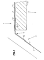
- the mounting bar serves for the simplified Installation or assembly of a vapor barrier at the transition area between one Building interior wall 2 in the form of a sloping roof and a ceiling 3.
- the Vapor barrier is in the usual way of a film 4 made of a plastic material formed in a suitable manner parallel to the inside of the roof Roof surface is laid.
- a angular connection or mounting profile 6 which consists of a suitable plastic is made, with two legs 6.1 and 6.2, the one the course of the roof slope or the wall 2 and the ceiling 3 in Include the corresponding connection area with an angle greater than 90 °, this angle due to the inherent elasticity of the angle profile 6 used material can also be reduced.
- Embodiment is a film blank 7 on the outside of the angle profile 6 attached, which extends over the entire length of the angle profile 6 and each protrudes with edge regions over the free ends of the legs 6.1 and 6.2, so that when the mounting strip is installed, the transition between foils 4 and 5 is not only is covered by the angle profile 6 or its legs 6.1 and 6.2, but additionally through the overlapping and interconnected (e.g. glued) foils or foil cut 4, 5 and 7.
- the leg 6.1 self-adhesive i.e. in the illustrated embodiment with a Adhesive application 8, which before use by a peelable flat material, is covered, for example, by a strip of silicone paper.
- the Self-adhesive layer 8 can, for example, also be double-sided Adhesive tape be formed.
- the angle profile 6 with the Apply adhesive 8 (after removing the cover from the flat material) on the one side facing away from the building interior is the visible underside of the ceiling forming ceiling material 3.1, for example on the top of a Ceiling element made of wood or another material, for example Gypsum cardboard plate glued so that the leg 6.1 over the edge of this Ceiling element protrudes and the leg 6.2 with its outer side after mounting the ceiling element 3.1 in the plane of the film 4 formed vapor barrier lies so that the film connected to the film blank 7 4 is held at the connection area between the wall 2 and ceiling 3 and also the Transition between the two films 4 and 5 is sealed.
- a Ceiling element made of wood or another material, for example Gypsum cardboard plate glued so that the leg 6.1 over the edge of this Ceiling element protrudes and the leg 6.2 with its outer side after mounting the ceiling element 3.1 in the plane of the film 4 formed vapor barrier lies so that the film connected to the film blank 7 4 is held at the connection area between the wall 2 and ceiling 3 and also the Transition between the two films 4 and 5
- connection profile 1 After mounting the ceiling element 3.1 with the connection profile 1 can then the further completion of the building wall 6 takes place, for example, by Applying the plaster 9, etc.
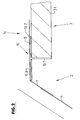
- FIG. 2 shows a further possible embodiment of an assembly bar 1 a differs from the mounting bar 1 essentially in that instead of Angle profile 6 a T-profile is used, with one after installation vertical profile section 10.1 and a horizontal after installation Profile section consisting of subsections 10.2 and 10.3, which at embodiment shown with the same width over the two sides of the Profile section 10.1 stand out and is arranged in a plane that is perpendicular to Level of the profile section 10.1 is.
- the self-adhesive layer 8 is in turn applied on one side of the partial length 10.2, with which the profile 10 are attached to the top of a ceiling element 3.1 can, at the edge of this ceiling element 3.1 such that the profile section 10.1 rests against the edge of the ceiling element 3.1 and here to the bottom of the ceiling element 3.1 is sufficient, while the other section 10.3 of the Edge of the ceiling element 3.1 stands out.
- the Foil cut 7 is attached, after installing the with the end profile 1a Pre-assembled ceiling element 3.1 is connected to the film 4 and thus the Transition between the film forming the vapor barrier in the area of the sloping roof 4 and covers the film 5 forming the vapor barrier in the area of the ceiling 3 or concludes.
- the mounting rails 1 and 1a in this way be used that after installing the with the respective mounting bar connected ceiling element 3.1 the mounting bar or the one provided there Foil cut is connected to the already assembled foil 4.
- the mounting bar can also be used so that the film 4 first with the mounting bar 1 or 1a or connected to the film blank 7 there, in Connecting it to the ceiling element 3.1 with that on this ceiling element provided mounting bar and only then the film 4 in the area Roof slope is attached.
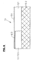
- FIGS. 3 and 4 show a further preferred embodiment Mounting strip 1b, which is not like the mounting strips 1 and 1a at the transition between a sloping roof 2 and a horizontal ceiling 3, but at the transition between a vertical building wall 11 and a subsequent roof slope 2 is used.
- the mounting bar 1b consists of a plastic, for example manufactured U-profile 12 with the two legs 12.1 and 12.2 and with this Leg-connecting profile or yoke section 12.3.
- the Mounting bar from an angle piece 13, which is shown in the Embodiment is formed from an expanded metal and two legs 13.1 and 13.2.
- the U-profile 12 is attached, specifically in Area of the free edge of this leg with that of the legs 12.1 and 12.2 facing away from the outside of the profile section 12.3 such that the legs 12.1 and 12.2 lie parallel to the leg 13.2 and with the leg 13.2 over a stand common side of the leg 13.1.
- the U-profile 12 is one provided a certain distance from the leg 13.2.
- the leg also has 13.2 a slightly larger width than the legs 12.1 and 12.2.
- a band 14 extends from the profile section 12.3 a flat material.
- the tape 14 is, for example, a self-adhesive tape, which, for example, with its back in a suitable manner on the legs 12.1 and 12.2 facing away from the profile section 12.3 and its Adhesive layer until later use due to a peelable flat material, is covered for example by silicone paper.
- the self-adhesive side is for example the side of the band 14 facing away from the U-profile.
- the U-profile, the angle profile 13 and the band 14 each extend over the total length of the mounting bar 1b.
- a continuous angle profile 13 several legs 13.1 and 13.2 Providing elbows, which are then in the longitudinal direction of the U-profile are successively provided on this.
- the elbow 13 it is also possible instead of the elbow 13 to use a profile element, which continuously has the leg 13.1, but instead of a continuous leg 13.2 several leg sections successive in the longitudinal direction of the profile are provided are.
- FIG 3 shows the use of the mounting bar 1b. This is before Plastering the inner surface of the building wall 11 fixed to it, with the help of the leg 13.2 or the corresponding leg sections in particular simply by using a mortar or other suitable Material of the leg 13.2 is fixed to the inner surface of the building wall 11.
- the Assembly of the mounting bar 1b takes place at a level at which the Plaster the inner wall of the inner surface of the roof slope 2 to the vertical Connects inner surface of the plastered building wall 11.
- the Assembly of the mounting bar such that the legs 12.1 and 12.2 as well as the Leg 13.2 project downward from leg 13.1.
- the profile strip 12 with its legs is in the plaster 15 embedded.
- the angle profile 13 at least with the leg 13.2 or the corresponding leg sections.
- the band 14 depends freely on the Assembly bar 1b away.
Landscapes
- Engineering & Computer Science (AREA)
- Architecture (AREA)
- Civil Engineering (AREA)
- Structural Engineering (AREA)
- Finishing Walls (AREA)
- Building Environments (AREA)
Applications Claiming Priority (4)
| Application Number | Priority Date | Filing Date | Title |
|---|---|---|---|
| DE20215216 | 2002-10-01 | ||
| DE20215216U | 2002-10-01 | ||
| DE20215607U | 2002-10-10 | ||
| DE20215607U DE20215607U1 (de) | 2002-10-01 | 2002-10-10 | Anschlußbereich zwischen einer als Dachschräge ausgeführten Gebäudeinnenwand und einer angrenzenden Gebäudewand oder Raumdecke und Montageleiste bei einem solchen Anschlußbereich |
Publications (2)
| Publication Number | Publication Date |
|---|---|
| EP1405963A2 true EP1405963A2 (fr) | 2004-04-07 |
| EP1405963A3 EP1405963A3 (fr) | 2004-12-15 |
Family
ID=31995345
Family Applications (1)
| Application Number | Title | Priority Date | Filing Date |
|---|---|---|---|
| EP03020145A Withdrawn EP1405963A3 (fr) | 2002-10-01 | 2003-09-05 | Zone de connection et profil de montage pour un mur à faíte incliné |
Country Status (1)
| Country | Link |
|---|---|
| EP (1) | EP1405963A3 (fr) |
Family Cites Families (4)
| Publication number | Priority date | Publication date | Assignee | Title |
|---|---|---|---|---|
| DE9409351U1 (de) * | 1994-06-09 | 1994-09-08 | Dürr, Walter, 74238 Krautheim | Eckprofil für Gipskartonplatten |
| DE19826955A1 (de) * | 1998-06-17 | 1999-12-30 | Gima Gipser Und Malerbedarf Gm | Vorrichtung zum Befestigen von Dampfbremsfolien |
| DE19950130A1 (de) * | 1999-10-18 | 2001-06-13 | August Braun | Eine an einem Fensterrahmen oder Türrahmen anbringbare Leiste |
| WO2001034922A1 (fr) * | 1999-11-09 | 2001-05-17 | Henkel Kommanditgesellschaft Auf Aktien | Bande de film, cadre de fenetre pourvu d'une telle bande et utilisation de cette bande |
-
2003
- 2003-09-05 EP EP03020145A patent/EP1405963A3/fr not_active Withdrawn
Also Published As
| Publication number | Publication date |
|---|---|
| EP1405963A3 (fr) | 2004-12-15 |
Similar Documents
| Publication | Publication Date | Title |
|---|---|---|
| CH699782A2 (de) | Rahmenanschlussteil zur Befestigung an einem Rahmen. | |
| EP0196672A2 (fr) | Panneaux pour recouvrir les murs extérieurs de bâtiments | |
| EP1659254B1 (fr) | Vantail de porte ou fenêtre | |
| EP0918127B1 (fr) | Châssis de porte et dispositif de montage | |
| AT501199B1 (de) | Zweiteiliges laibungsanschlussprofil für an putz angrenzende bauteile | |
| WO2008092699A1 (fr) | Dispositif d'inspection, en particulier élément de recouvrement d'inspection | |
| EP0279820B1 (fr) | Elements de panneaux prefabriques pour la realisation de chambres isolantes | |
| EP3121358B1 (fr) | Élement de chassis et chassis de membrane ainsi fabrique | |
| DE2808328C3 (de) | Wandelement | |
| DE9303937U1 (de) | Sanitaerkabine | |
| DE2934940C2 (de) | Außenfenster zum Verdecken einer Öffnung in einer mit einer Außenverkleidung versehenen Gebäudewand | |
| EP0470603A1 (fr) | Dispositif d'étanchéité pour cadre de porte ou fenêtre | |
| DE102010009376A1 (de) | Putzabschlussprofil und Verfahren zur Herstellung eines Anschlusses zwischen zwei Wänden | |
| EP3168403B1 (fr) | Système d'isolation et d'étanchéification combiné | |
| DE2120445A1 (de) | Vorrichtung zum Befestigen von Zwischentrennwänden in Bauwerken | |
| DE102015108708A1 (de) | Kombiniertes Dicht- und Dämmsystem | |
| DE9409351U1 (de) | Eckprofil für Gipskartonplatten | |
| DE102012212551A1 (de) | Dämmplatte für Fensterlaibungen | |
| DE2426718C3 (de) | Flügelrahmen für Fenster, Türen o.dgl. mit wenigstens zwei im Abstand voneinander angeordneten Glasscheiben | |
| DE20215607U1 (de) | Anschlußbereich zwischen einer als Dachschräge ausgeführten Gebäudeinnenwand und einer angrenzenden Gebäudewand oder Raumdecke und Montageleiste bei einem solchen Anschlußbereich | |
| DE29913256U1 (de) | Profilsystem zur Erstellung von Tageslichtbändern | |
| EP3115526A1 (fr) | Étanchéification de joints entre des éléments d'isolation destinés à l'isolation de bâtiment | |
| DE202006009790U1 (de) | Zweiteiliges Laibungsanschlussprofil | |
| DE1945940A1 (de) | Abdichtung fuer Dehnungsfugen in Bauwerken | |
| EP0495150A1 (fr) | Construction de façade |
Legal Events
| Date | Code | Title | Description |
|---|---|---|---|
| PUAI | Public reference made under article 153(3) epc to a published international application that has entered the european phase |
Free format text: ORIGINAL CODE: 0009012 |
|
| AK | Designated contracting states |
Kind code of ref document: A2 Designated state(s): AT BE BG CH CY CZ DE DK EE ES FI FR GB GR HU IE IT LI LU MC NL PT RO SE SI SK TR |
|
| AX | Request for extension of the european patent |
Extension state: AL LT LV MK |
|
| PUAL | Search report despatched |
Free format text: ORIGINAL CODE: 0009013 |
|
| AK | Designated contracting states |
Kind code of ref document: A3 Designated state(s): AT BE BG CH CY CZ DE DK EE ES FI FR GB GR HU IE IT LI LU MC NL PT RO SE SI SK TR |
|
| AX | Request for extension of the european patent |
Extension state: AL LT LV MK |
|
| 17P | Request for examination filed |
Effective date: 20050202 |
|
| AKX | Designation fees paid |
Designated state(s): AT BE BG CH CY CZ DE DK EE ES FI FR GB GR HU IE IT LI LU MC NL PT RO SE SI SK TR |
|
| 17Q | First examination report despatched |
Effective date: 20071017 |
|
| STAA | Information on the status of an ep patent application or granted ep patent |
Free format text: STATUS: THE APPLICATION IS DEEMED TO BE WITHDRAWN |
|
| 18D | Application deemed to be withdrawn |
Effective date: 20090114 |