EP1405979A1 - Verbindungsvorrichtung, Abdeckvorrichtung und Trennelement - Google Patents
Verbindungsvorrichtung, Abdeckvorrichtung und Trennelement Download PDFInfo
- Publication number
- EP1405979A1 EP1405979A1 EP02405853A EP02405853A EP1405979A1 EP 1405979 A1 EP1405979 A1 EP 1405979A1 EP 02405853 A EP02405853 A EP 02405853A EP 02405853 A EP02405853 A EP 02405853A EP 1405979 A1 EP1405979 A1 EP 1405979A1
- Authority
- EP
- European Patent Office
- Prior art keywords
- elastic element
- sealing lip
- profile
- cover plate
- glass plate
- Prior art date
- Legal status (The legal status is an assumption and is not a legal conclusion. Google has not performed a legal analysis and makes no representation as to the accuracy of the status listed.)
- Granted
Links
- 238000005192 partition Methods 0.000 title description 2
- 239000011521 glass Substances 0.000 claims abstract description 41
- 238000007789 sealing Methods 0.000 claims abstract description 30
- 230000007704 transition Effects 0.000 claims description 11
- 229920001971 elastomer Polymers 0.000 claims description 9
- 239000000463 material Substances 0.000 claims description 9
- 238000003825 pressing Methods 0.000 claims description 8
- 230000006835 compression Effects 0.000 claims description 4
- 238000007906 compression Methods 0.000 claims description 4
- 244000043261 Hevea brasiliensis Species 0.000 claims description 3
- 239000000853 adhesive Substances 0.000 claims description 3
- 230000001070 adhesive effect Effects 0.000 claims description 3
- 239000000806 elastomer Substances 0.000 claims description 3
- 229920003052 natural elastomer Polymers 0.000 claims description 3
- 229920001194 natural rubber Polymers 0.000 claims description 3
- 238000007493 shaping process Methods 0.000 claims 1
- 229920001821 foam rubber Polymers 0.000 abstract 1
- 238000004519 manufacturing process Methods 0.000 description 3
- 241001295925 Gegenes Species 0.000 description 2
- 229920001296 polysiloxane Polymers 0.000 description 2
- 239000007858 starting material Substances 0.000 description 2
- 238000009434 installation Methods 0.000 description 1
- 238000000034 method Methods 0.000 description 1
- 239000003566 sealing material Substances 0.000 description 1
Images


Classifications
-
- E—FIXED CONSTRUCTIONS
- E06—DOORS, WINDOWS, SHUTTERS, OR ROLLER BLINDS IN GENERAL; LADDERS
- E06B—FIXED OR MOVABLE CLOSURES FOR OPENINGS IN BUILDINGS, VEHICLES, FENCES OR LIKE ENCLOSURES IN GENERAL, e.g. DOORS, WINDOWS, BLINDS, GATES
- E06B3/00—Window sashes, door leaves, or like elements for closing wall or like openings; Layout of fixed or moving closures, e.g. windows in wall or like openings; Features of rigidly-mounted outer frames relating to the mounting of wing frames
- E06B3/30—Coverings, e.g. protecting against weather, for decorative purposes
- E06B3/301—Coverings, e.g. protecting against weather, for decorative purposes consisting of prefabricated profiled members or glass
- E06B3/305—Covering metal frames with plastic or metal profiled members
-
- E—FIXED CONSTRUCTIONS
- E06—DOORS, WINDOWS, SHUTTERS, OR ROLLER BLINDS IN GENERAL; LADDERS
- E06B—FIXED OR MOVABLE CLOSURES FOR OPENINGS IN BUILDINGS, VEHICLES, FENCES OR LIKE ENCLOSURES IN GENERAL, e.g. DOORS, WINDOWS, BLINDS, GATES
- E06B3/00—Window sashes, door leaves, or like elements for closing wall or like openings; Layout of fixed or moving closures, e.g. windows in wall or like openings; Features of rigidly-mounted outer frames relating to the mounting of wing frames
- E06B3/02—Wings made completely of glass
-
- E—FIXED CONSTRUCTIONS
- E06—DOORS, WINDOWS, SHUTTERS, OR ROLLER BLINDS IN GENERAL; LADDERS
- E06B—FIXED OR MOVABLE CLOSURES FOR OPENINGS IN BUILDINGS, VEHICLES, FENCES OR LIKE ENCLOSURES IN GENERAL, e.g. DOORS, WINDOWS, BLINDS, GATES
- E06B3/00—Window sashes, door leaves, or like elements for closing wall or like openings; Layout of fixed or moving closures, e.g. windows in wall or like openings; Features of rigidly-mounted outer frames relating to the mounting of wing frames
- E06B3/54—Fixing of glass panes or like plates
- E06B3/58—Fixing of glass panes or like plates by means of borders, cleats, or the like
- E06B3/62—Fixing of glass panes or like plates by means of borders, cleats, or the like of rubber-like elastic cleats
- E06B2003/6238—Fixing of glass panes or like plates by means of borders, cleats, or the like of rubber-like elastic cleats having extra functions
Definitions
- the invention relates to a connecting device, one with this connection device provided cover and a separating element, in particular a sliding door, after the The preamble of claim 1, 9 and 12, respectively.
- the invention particularly relates to a cover device, by means of the one serving to hold a glass plate, Optionally disturbing appearing in appearance Mounting device to be covered.
- Devices for holding glass plates are, for example from WO 02/10544 A1 or EP 0 940 542 A2. These Devices have a clamping device with two means a screw against each other movable elements, between which a glass plate is frictionally held.
- Figure 1 showed a means of drives 9 and a Guide pin 90 along an upper and lower rail 7, 70 guided sliding door.
- the sliding door is with a Device provided for positively holding a Plate 4, in particular a glass plate, is used.
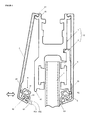
- This shown in Figure 2 in a side section Device has at least one through an opening 41 in the Glass plate 4 feasible support member 3, by means of which a first profile piece 1 and a second profile piece 2, the on opposite sides of the glass plate. 4 be arranged, are connected to each other.
- the Support member 3 has a head portion 31, which in a in the first Profile piece 1 provided receiving groove 13 slidably held as well as a through the opening 41 to be led Connecting part 32 with a threaded hole 33, the Recording one of the connection of the second profile element. 2 Serving mounting screw 35 is provided.
- a threaded pin 34 is arranged by means of which the support element 3 within the receiving groove 13th can be fixed.
- the glass plate 4 can therefore on the in the first profile piece. 1 used supporting elements 3 suspended and in a desired Able to be moved. After fixing the support elements. 3 the second profile piece 2 is placed and screwed, whereby the glass plate 4 is firmly clamped.
- the two interconnected profile pieces 1 and 2 form a profile element 12, which at the upper and lower edge 18, 19 with retaining elements 15, 16, cams, strips or Wing pieces, which is the attachment of a Cover plate 5 serve, at the bottom and top of the Clasping the holding elements 15, 16 serving staple-like Connecting means 51 are provided.
- a cover plate 5 serves, at the bottom and top of the Clasping the holding elements 15, 16 serving staple-like Connecting means 51 are provided.
- elastic bands 8 are provided, which at Tighten the mounting screws 35 slightly compressed become.
- a mounting block 91 is inserted, which by means of a screw 92 with an associated Drive 9 is connected (see Figure 1).
- a seal such as a Silicone paste to apply, or the elastic bands 8 such that they the two profile parts 1, 2 slightly overlap and thereby form seals.
- the present invention is therefore based on the object to provide a device which can be produced cost-effectively by means of a first part, in particular a cover plate, positive but detachable with a second part, in particular a profile part, is connectable and by means of the Transition area between the first part and a third one Part can be reliably sealed. Furthermore, one with this connection device provided cover and a door element provided with the cover device create.
- the first part for example a cover plate
- the cover plate means the elastic element is positively connected to the second part,
- a profile part is connected.
- the Seal lip is so on the elastic element arranged that after fitting the cover plate to a connected to the profile part third part, for example a glass plate of a separating element, presses.
- a provided with the inventive cover Separating element such as a sliding door, therefore be cleaned easily. Furthermore, created by the Covering disturbing transition areas an improved aesthetic appearance of the covering device provided separating element.
- the sealing lip is preferably more flexible designed as the remaining body of the elastic Elements, leaving the cover plate and the profile element stable, but releasably connectable to each other, and the Sealing lip deformed by pressing against the glass plate is, whereby the sealing lip by means of surface pressure on the glass plate rests.
- the desired elasticity of the sealing lip and the remaining body of the elastic element can through the Choice of material for each part of the elastic element and / or also be achieved by their shape.
- the sealing lip has a hardness of less as 50 Sh_A (Shore A), preferably about 10 Sh_A to 30 Sh_A, and the other components of the elastic element a Hardness greater than 50 Sh_A, preferably about 70 Sh_A to 90 Sh_A, on.
- Shore A complies with DIN 53505 and is used in soft rubber, elastomers, and natural rubber products).
- the elastic element according to the invention is preferably made made in one piece.
- the sealing lip can with the however, remaining body of the elastic member also be connected or welded by means of an adhesive.
- the elastic element is made in one piece, For example, two starting materials with corresponding Material properties merged and extruded in such a way that the subregions of the elastic element the desired Have material hardness.
- the latching element has a shape adapted to a holding element and is preferably with elastic element body so compressible that it is over, under or in the Retaining element is displaced and then positively relaxed on the retaining element.
- the body of the elastic member extending in the axial direction Compression channel, which is deformed as soon as the Pressing force acts on the locking element.
- the cover consists of a cover plate with a Holding rib on which the elastic element is placed.
- the cover plate preferably has second connecting means on, by means of which they can be connected on one side with the profile part is.
- the cover plate by means of the second Connecting means at one on the upper edge of the profile part provided upper retaining element suspended, after which the Detent element under one at the lower edge of the profile part provided lower retaining element is pressed through.
- the locking element also under a at the Lower edge of the profile part provided lower retaining element passed, after which the cover plate is raised and the elastic element is compressed so that the second Guided connecting means over the upper holding means and can be hung on it.
- a connected with a glass plate profile part therefore has preferably two on each or both sides, preferably arranged at the top and bottom edges Holding elements, with which the second connecting means and the locking element provided on the elastic element are positively connected.
- a partition provided with a glass plate for example, a sliding door (see Figures 1 and 2), can Therefore, in a few steps with the inventive Covering be provided, after which also the Transition area between the cover plate of Cover device and the glass plate is sealed.
- Figure 1 shows the initially described, with a Glass plate 4 provided sliding door by means of drives 9 and a guide pin 90 along an upper and a lower rail 7, 70 is guided.
- the sliding door is with the in Figure 2 in sectional view shown device provided for positively holding the glass plate. 4 serves.
- This shown in Figure 2 in a side section Device has at least one through an opening 41 in the Glass plate 4 feasible support member 3, by means of which a first profile piece 1 and a second profile piece 2, the on opposite sides of the glass plate. 4 be arranged, are connected to each other.
- the two interconnected profile pieces 1 and 2 form a Profile element 12, which at the upper and lower edge 18, 19 provided with holding elements 15, 16, cams or wing pieces is that serve the attachment of a cover plate 5.
- FIG 3 shows the profile element of Figure 2 with upper and lower holding elements 15, 16 in a preferred manner Embodiment and two inventive cover devices, consisting of a cover plate 5 and a mounted on it consist elastic element 6.
- the cover plates 5 are on the bottom with an axially extending, for holding the elastic member 6 serving holding rib 52 and on the Top with a wing-like connecting means 51 provided, which as a second connecting element for hanging the cover plate 5 on the upper support members 15 of the Profile part 12 is used.
- the elastic element 6 has a channel 61 for receiving the Holding rib 52 and a latching element 62, which with a the inclusion of a holding element 16 serving sink 621 and a nose 622 serving to lock the retaining element 16 is provided. Further, the elastic member 6 with a Sealing lip 63 provided after assembly of the Covering device to the held by the profile element 12 Glass plate 4 presses.
- the cover plate 5 in the Mounting for example, first on the upper holding element 15th mounted, after which provided with the elastic element 6 Bottom of the cover plate 5 against the lower support member 16th is pressed until the nose 622 under the lower retaining element 16 slides into the sink 621 inside, whereby the positive connection between the profile element 12 and the cover arises.
- the sealing lip 63 is so arranged on the elastic element 6, that they are after assembly the cover plate 5 presses against the glass plate 4.
- the sealing lip 63 is preferably more flexible designed as the remaining body 66 of the elastic Elements 6, so that the cover plate 5 and the profile element 12 stable, but releasably connectable to each other, and the Seal lip 63 by pressing against the glass plate. 4 is deformed, whereby the sealing lip 63 by means of Surface pressure applied to the glass plate 4.
- the desired elasticity of the sealing lip 63 and the remaining body 66 of the elastic member 6 can by the choice of material for each part of the elastic element 6 and / or also be achieved by the shape thereof.
- the sealing lip 63 has a hardness of less than 50 Sh_A (Shore A). preferably about 10 Sh_A until 30 Sh_A, and the other components 66 of the elastic Element 6 has a hardness greater than 50 Sh_A, preferably about 70 Sh_A to 90 Sh_A, up.
- Shore A complies with standard DIN 53505 and finds application in soft rubber, elastomers, and Natural rubber products, which are used for the production of elastic member 6 are usable.
- sponge rubber is advantageously applicable.
- sealing lip 63 may also be relatively thin and long be so lightly pressed against the glass plate 4 can be.
- the elastic element 6 is preferably made in one piece manufactured.
- the sealing lip 63 can with the remaining Body 66 of the elastic member 6, however, by means of a Adhesive be connected or welded.
- the elastic element 6 is manufactured in one piece, For example, two starting materials with corresponding Material properties merged and extruded in such a way that the subregions of the elastic element the desired Have material hardness.
- FIG. 4 shows the covering device in a preferred manner Embodiment with an elastic element 6, which a longitudinally extending compression channel 64, the is deformed as soon as a pressing force on the locking element 62 acts so that the cover device mounted easily and can be dismantled.
- the assembled cover device can also be upwards are pressed so that the upper connecting means 51 from the upper support member 15 dissolves and the cover can be removed again.
- the latching element 62 is suspended on the lower holding element 16, whereafter the cover device is pressed up until the provided on the cover plate second connecting means 51 in the upper provided on the profile element 12 retaining element 15th can be introduced.
- FIG. 6 shows the elastic element 6 in detail. It is it can be seen that the sealing lip 63 consists of a lower and an upper lip 631; 632, which after assembly of the Covering device to be unfolded and wide against the Press glass plate 4.
- the inventive connecting device was in a preferred embodiment described and illustrated. Based however, the teachings of the invention are more expert Embodiments realizable. In particular, different ones Embodiments and dimensions of the device parts selectable and various manufacturing materials for their production usable.
- the elastic element 6 may also be such be configured that the positive connection between the first and the second part without additional Connecting elements is possible.
Landscapes
- Engineering & Computer Science (AREA)
- Civil Engineering (AREA)
- Structural Engineering (AREA)
- Securing Of Glass Panes Or The Like (AREA)
- Seal Device For Vehicle (AREA)
- Piezo-Electric Or Mechanical Vibrators, Or Delay Or Filter Circuits (AREA)
- Light Receiving Elements (AREA)
- Pressure Sensors (AREA)
- Casings For Electric Apparatus (AREA)
- Specific Sealing Or Ventilating Devices For Doors And Windows (AREA)
Abstract
Description
- Figur 1
- eine mittels Laufwerken 9 und einem Führungsstift 90 entlang einer oberen und einer unteren Schiene 7; 70 geführte Schiebetür, die mit einer Vorrichtung zum Halten einer Glasplatte versehen ist,
- Figur 2
- die Vorrichtung von Figur 1 in einem Seitenschnitt dargestellt mit einem zweistückigen Profilelement 12 an dem eine Abdeckplatte 5' befestigt ist,
- Figur 3
- das Profilelement 12 von Figur 2 mit vorzugsweise ausgestalteten oberen und unteren Halteelementen 15, 16, an denen erfindungsgemässe Abdeckvorrichtungen befestigt werden können, die aus einer Abdeckplatte 5 und einem elastischen Element 6 bestehen,
- Figur 4
- in einer vorzugsweisen Ausgestaltung, die Abdeckvorrichtungen von Figur 3, von denen eine oben am Profilelement 12 eingehängt ist und unten gegen das Profilelement 12 gedrückt wird,
- Figur 5
- die Abdeckvorrichtungen von Figur 4, von denen eine unten am Profilelement 12 eingehängt ist, angehoben und oben gegen das Profilelement 12 gedrückt wird, und
- Figur 6
- das elastische Element 6 in der Ausgestaltung von Figur 4.
- 1
- erstes Profilstück
- 11
- Oberteil des Profilelements 12
- 12
- Profilelement bestehend aus dem ersten und zweiten Profilstück 1, 2
- 13
- Aufnahmenut
- 14
- Unterteil des Profilelements 12
- 15
- obere Halteelemente
- 16
- untere Halteelemente
- 18
- Oberkante des Profilelements 12
- 19
- Unterkante des Profilelements 12
- 2
- zweites Profilstück
- 22
- Montagerippe
- 3
- Tragelement
- 31
- Kopfteil
- 32
- Verbindungsteil
- 33
- Gewindebohrung
- 34
- Gewindestift
- 35
- Montageschraube
- 4
- Glasplatte
- 41
- Loch in der Glasplatte 40
- 5
- Abdeckplatte
- 51
- Verbindungsmittel
- 52
- Halterippe
- 6
- elastisches Element
- 61
- Kanal zur Aufnahme der Halterippe 52
- 62
- Rastelement
- 621
- Senke
- 622
- Nase
- 63
- Dichtungslippe
- 631
- Oberlippe
- 632
- Unterlippe
- 64
- Kompressionskanal
- 66
- Körper
- 7
- obere Führungsschiene
- 70
- untere Führungsschiene
- 8
- elastische Bänder
- 9
- Laufwerk
- 90
- Führungsstift
- 91
- Montageblock
- 92
- Verbindungsschraube
Claims (12)
- Vorrichtung zum formschlüssigen, aber lösbaren Verbinden eines ersten Teils (5) mit einem zweiten Teil (12) sowie zum Abdichten eines Übergangsbereichs zwischen dem ersten Teil (5) und einem dritten Teil (4), welches mit dem zweiten Teil (12) verbunden ist, dadurch gekennzeichnet, dass ein elastisches Element (6) vorgesehen ist, welches aufweista) einen Kanal (61) zur Aufnahme einer am ersten Teil (5) vorgesehenen Halterippe (52),b) ein Rastelement (62), das mittels Andruckkraft mit dem zweiten Teil (12) formschlüssig verbindbar ist undc) eine Dichtungslippe (63), die nach dem Einrasten des Rastelements (62) an das dritte Teil (4) andrückt.
- Vorrichtung nach Anspruch 1, dadurch gekennzeichnet, dass das elastische Element (6) aus einem Stück gefertigt ist oder dass die Dichtungslippe (63) mit dem verbleibenden Körper (66) des elastischen Elements (6) mittels eines Klebstoffs verbunden oder verschweisst ist.
- Vorrichtung nach Anspruch 1 oder 2, dadurch gekennzeichnet, dass die Dichtungslippe (63) weichelastischer ausgestaltet ist, als der verbleibende Körper (66) des elastischen Elements (6), der mit dem Kanal (61) und dem Rastelement (62) versehen ist, so dass das erste und das zweite Teil (5, 12) nach dem gegenseitigen formschlüssigen Verbinden stabil gehalten sind und die Dichtungslippe (63) durch das Andrücken an das dritte Teil (4) verformt ist.
- Vorrichtung nach Anspruch 3, dadurch gekennzeichnet, dass die Elastizität der Dichtungslippe (63) und des verbleibenden Körpers (66) des elastischen Elements (6) durch die Wahl des Materials oder durch die Formgebung erzielt wird.
- Vorrichtung nach Anspruch 4, dadurch gekennzeichnet, dass die Dichtungslippe (63) eine Härte von weniger als 50 Sh_A, vorzugsweise etwa 10 Sh_A bis 30 Sh_A, und die weiteren Bestandteile des elastischen Elements (6) eine Härte von grösser 50 Sh_A, vorzugsweise etwa 70 Sh_A bis 90 Sh_A, aufweisen.
- Vorrichtung nach Anspruch 5, dadurch gekennzeichnet, dass der Körper (66) und oder die Dichtungslippe (63) aus Weichgummi, Elastomeren, Naturkautschuk, die Dichtungslippe (63) insbesondere aus Moosgummi gefertigt sind.
- Vorrichtung nach einem der Ansprüche 1 bis 6, dadurch gekennzeichnet, dass das Rastelement (62) in den Körper (66) des elastischen Elements (6) hinein drückbar ist.
- Vorrichtung nach einem der Ansprüche 1 bis 7, dadurch gekennzeichnet, dass der Körper (66) des elastischen Elements (6) einen in axialer Richtung verlaufenden Kompressionskanal (64) aufweist, der deformiert wird, sobald die Andruckkraft auf das Rastelement (62) einwirkt.
- Abdeckvorrichtung mit einer Verbindungsvorrichtung nach einem der Ansprüche 1 bis 8, dadurch gekennzeichnet, dass das erste Teil (5) eine Abdeckplatte, das zweite Teil (12) ein durch das erste Teil (5) abzudeckendes, gegebenenfalls aus zwei oder mehreren Stücken (1, 2) zusammengesetztes Profilteil und das dritte Teil (4) eine Platte, insbesondere eine Glasplatte ist, die mittels des zweiten Teils (1, 2) zumindest einseitig gehalten ist.
- Abdeckvorrichtung nach Anspruch 9, dadurch gekennzeichnet, dass die Abdeckplatte (5), an deren Halterippe (52) das elastische Element (6) aufgesetzt ist, zweite Verbindungsmittel (51) aufweist, mittels denen die Abdeckplatte (5) einseitig mit dem Profilteil (12) verbindbar ist.
- Abdeckvorrichtung nach Anspruch 10, dadurch gekennzeichnet, dass das mit der Glasplatte (4) verbundene Profilteil (12) auf einer oder beiden Seiten je zwei, vorzugsweise an deren Ober- und Unterkante angeordnete Halteelemente (15, 16) aufweist, mit denen die zweiten Verbindungsmittel (51) und das am elastischen Element (6) vorgesehene Rastelement (62) formschlüssig verbindbar sind.
- Trennelement, insbesondere Schiebetür, mit einem zum Halten einer Platte (4), insbesondere einer Glasplatte dienenden Profilteil (12), das mittels einer Abdeckvorrichtung nach einem der Ansprüche 9 bis 11 derart abgedeckt ist, dass der Übergangsbereich zwischen einer Abdeckplatte der Abdeckvorrichtung und der Platte (4) dicht abgedeckt ist.
Priority Applications (9)
| Application Number | Priority Date | Filing Date | Title |
|---|---|---|---|
| ES02405853T ES2295310T3 (es) | 2002-10-02 | 2002-10-02 | Dispositivo de union, dispositivo de cubierta y elemento separador. |
| AT02405853T ATE377124T1 (de) | 2002-10-02 | 2002-10-02 | Verbindungsvorrichtung, abdeckvorrichtung und trennelement |
| EP02405853A EP1405979B1 (de) | 2002-10-02 | 2002-10-02 | Verbindungsvorrichtung, Abdeckvorrichtung und Trennelement |
| DE50211142T DE50211142D1 (de) | 2002-10-02 | 2002-10-02 | Verbindungsvorrichtung, Abdeckvorrichtung und Trennelement |
| US10/662,446 US20040065019A1 (en) | 2002-10-02 | 2003-09-16 | Connecting device, cover device and dividing element |
| AU2003248289A AU2003248289A1 (en) | 2002-10-02 | 2003-09-22 | Connecting device, cover device and dividing element |
| CA2443281A CA2443281C (en) | 2002-10-02 | 2003-09-29 | Connecting device, cover device and dividing element |
| JP2003344482A JP2004124702A (ja) | 2002-10-02 | 2003-10-02 | 結合装置、カバー装置および分離部材 |
| MXPA03008993A MXPA03008993A (es) | 2002-10-02 | 2003-10-02 | Dispositivo de union, dispositivo de cubierta y elemento divisor. |
Applications Claiming Priority (1)
| Application Number | Priority Date | Filing Date | Title |
|---|---|---|---|
| EP02405853A EP1405979B1 (de) | 2002-10-02 | 2002-10-02 | Verbindungsvorrichtung, Abdeckvorrichtung und Trennelement |
Publications (2)
| Publication Number | Publication Date |
|---|---|
| EP1405979A1 true EP1405979A1 (de) | 2004-04-07 |
| EP1405979B1 EP1405979B1 (de) | 2007-10-31 |
Family
ID=31985175
Family Applications (1)
| Application Number | Title | Priority Date | Filing Date |
|---|---|---|---|
| EP02405853A Expired - Lifetime EP1405979B1 (de) | 2002-10-02 | 2002-10-02 | Verbindungsvorrichtung, Abdeckvorrichtung und Trennelement |
Country Status (9)
| Country | Link |
|---|---|
| US (1) | US20040065019A1 (de) |
| EP (1) | EP1405979B1 (de) |
| JP (1) | JP2004124702A (de) |
| AT (1) | ATE377124T1 (de) |
| AU (1) | AU2003248289A1 (de) |
| CA (1) | CA2443281C (de) |
| DE (1) | DE50211142D1 (de) |
| ES (1) | ES2295310T3 (de) |
| MX (1) | MXPA03008993A (de) |
Cited By (9)
| Publication number | Priority date | Publication date | Assignee | Title |
|---|---|---|---|---|
| FR2904354A1 (fr) * | 2006-07-25 | 2008-02-01 | Denis Metrat | Ouvrant a capot |
| WO2009003452A1 (de) * | 2007-07-02 | 2009-01-08 | Bangratz Rene | Glasscheiben-geländer |
| DE102009027236A1 (de) * | 2009-06-26 | 2010-12-30 | Geze Gmbh | Türanlage |
| CN107299803A (zh) * | 2016-04-14 | 2017-10-27 | 多玛凯拔德国有限公司 | 玻璃门夹配件 |
| EP3940164A1 (de) * | 2020-07-17 | 2022-01-19 | C.R. Laurence Co., Inc. | Verbessertes türschienensystem |
| EP3940165A1 (de) * | 2020-07-17 | 2022-01-19 | C.R. Laurence Co., Inc. | Verbessertes türschienensystem |
| US11692370B2 (en) | 2016-10-21 | 2023-07-04 | C.R. Laurence Co., Inc. | Taper-Loc system improvements |
| US11821238B2 (en) | 2018-04-18 | 2023-11-21 | C.R. Laurence Co., Inc. | Push pad exit device for emergency door egress |
| US12054970B2 (en) | 2018-04-18 | 2024-08-06 | C.R. Laurence Co., Inc. | Push pad exit device for emergency door egress and vertical latch bolt assembly |
Families Citing this family (8)
| Publication number | Priority date | Publication date | Assignee | Title |
|---|---|---|---|---|
| US20060032161A1 (en) * | 2004-07-24 | 2006-02-16 | Rytec Corporation | Door assembly and method of making same |
| EP2151538B8 (de) * | 2008-08-06 | 2017-05-03 | Hawa Sliding Solutions AG | Vorrichtung mit einem Laufwerk zum Halten von Platten, Laufwerk, Laufschiene und Trennelement |
| KR101584810B1 (ko) | 2009-07-03 | 2016-01-13 | (주) 엘지토스템비엠 | 글레이징 비드 장착용 어댑터와 이를 이용한 글레이징 비드의 고정 및 분리 방법 |
| CN102337826B (zh) * | 2011-10-08 | 2013-04-24 | 无锡金城幕墙装饰工程有限公司 | 单轨推拉门玻璃压线固定玻璃扇结构 |
| CN108150009B (zh) * | 2018-02-13 | 2024-05-03 | 东屋世安物联科技(江苏)股份有限公司 | 一种面板固定结构 |
| CN114458391A (zh) * | 2022-02-22 | 2022-05-10 | 中国联合重型燃气轮机技术有限公司 | 一种透平叶片锁紧组件 |
| CN115467604B (zh) * | 2022-08-18 | 2023-09-12 | 浙江迦南科技股份有限公司 | 一种用于包衣机密封性好的钢化玻璃门结构的太阳门 |
| TWM644838U (zh) * | 2023-03-02 | 2023-08-11 | 億泰興業有限公司 | 用於機械設備之電動門驅動機構 |
Citations (5)
| Publication number | Priority date | Publication date | Assignee | Title |
|---|---|---|---|---|
| US4235049A (en) * | 1978-02-08 | 1980-11-25 | Casma di B. Marinoni & Figli | Edge fitting assembly for a panel |
| US4524978A (en) * | 1983-08-31 | 1985-06-25 | Ampat/Midwest Corp. | Simulated structural gasket |
| EP0940542A2 (de) | 1998-03-06 | 1999-09-08 | Klein Iberica, S.A. | Montagevorrichtung für Glasschiebetüren |
| EP1106770A1 (de) * | 1999-12-07 | 2001-06-13 | Noah Widmer | Fensterflügel und Fenster |
| WO2002010544A1 (en) | 2000-08-02 | 2002-02-07 | C.R. Laurence Company, Inc. | Door rail system |
Family Cites Families (18)
| Publication number | Priority date | Publication date | Assignee | Title |
|---|---|---|---|---|
| US1575083A (en) * | 1926-03-02 | tracy | ||
| US3473266A (en) * | 1967-12-15 | 1969-10-21 | Stanley Works | Integrated header |
| AT285915B (de) * | 1968-02-13 | 1970-11-25 | Rudolf Ing Weikert | Isolierter Rahmen für Fenster, Türen, Wände, Sprossen od.dgl. |
| DE2152570C2 (de) * | 1970-10-28 | 1984-03-29 | The Schlegel Manufacturing Co., Rochester, N.Y. | Dichtungsleiste für Dachseitenholme |
| US3780472A (en) * | 1971-12-01 | 1973-12-25 | American Metal Climax Inc | Door structure |
| US4145844A (en) * | 1977-12-16 | 1979-03-27 | Ardco, Inc. | Refrigerator door construction |
| DE3011946C2 (de) * | 1980-03-27 | 1985-03-21 | Golde GmbH Spritzgußwerk, 8192 Geretsried | Schiebefenster oder -tür |
| CH666514A5 (de) * | 1984-05-24 | 1988-07-29 | Heinrich Saelzer | Rahmen fuer mit einer plattenfoermigen fuellung versehene bauteile. |
| JP2543917Y2 (ja) * | 1991-07-10 | 1997-08-13 | 豊田合成株式会社 | ウェザストリップ |
| US6260254B1 (en) * | 1996-07-09 | 2001-07-17 | Decoma International Inc. | Integrally formed B-pillar and belt-line window molding |
| DE19835400C2 (de) * | 1997-08-06 | 2002-12-05 | Nishikawa Rubber Co Ltd | Dichtungsanordnung für eine Kraftfahrzeugtür |
| DE19804859C1 (de) * | 1998-02-09 | 1999-08-26 | Dorma Gmbh & Co Kg | Schwenkbare Verbindung |
| DE19804860C1 (de) * | 1998-02-09 | 1999-08-26 | Dorma Gmbh & Co Kg | Gehäuse, insbesondere für automatische Türantriebe |
| JP3451582B2 (ja) * | 1999-02-22 | 2003-09-29 | 株式会社イトーキクレビオ | 窓 枠 |
| JP2000344025A (ja) * | 1999-03-31 | 2000-12-12 | Toyoda Gosei Co Ltd | 自動車用シール部品及びその製造装置及び製造方法 |
| US6148451A (en) * | 1999-04-14 | 2000-11-21 | Kohler Co. | Shower door attachment assembly |
| DE29916352U1 (de) * | 1999-09-17 | 2000-01-13 | Meteor Gummiwerke K. H. Bädje GmbH & Co, 31167 Bockenem | Fensterdichtungsprofil für ein Kabriolett |
| DE19962074C2 (de) * | 1999-12-21 | 2001-10-25 | Dorma Gmbh & Co Kg | Gehäuse, insbesondere für Antriebe von automatisch und horizontal verfahrbaren Elementen |
-
2002
- 2002-10-02 DE DE50211142T patent/DE50211142D1/de not_active Expired - Lifetime
- 2002-10-02 AT AT02405853T patent/ATE377124T1/de active
- 2002-10-02 ES ES02405853T patent/ES2295310T3/es not_active Expired - Lifetime
- 2002-10-02 EP EP02405853A patent/EP1405979B1/de not_active Expired - Lifetime
-
2003
- 2003-09-16 US US10/662,446 patent/US20040065019A1/en not_active Abandoned
- 2003-09-22 AU AU2003248289A patent/AU2003248289A1/en not_active Abandoned
- 2003-09-29 CA CA2443281A patent/CA2443281C/en not_active Expired - Fee Related
- 2003-10-02 JP JP2003344482A patent/JP2004124702A/ja active Pending
- 2003-10-02 MX MXPA03008993A patent/MXPA03008993A/es unknown
Patent Citations (5)
| Publication number | Priority date | Publication date | Assignee | Title |
|---|---|---|---|---|
| US4235049A (en) * | 1978-02-08 | 1980-11-25 | Casma di B. Marinoni & Figli | Edge fitting assembly for a panel |
| US4524978A (en) * | 1983-08-31 | 1985-06-25 | Ampat/Midwest Corp. | Simulated structural gasket |
| EP0940542A2 (de) | 1998-03-06 | 1999-09-08 | Klein Iberica, S.A. | Montagevorrichtung für Glasschiebetüren |
| EP1106770A1 (de) * | 1999-12-07 | 2001-06-13 | Noah Widmer | Fensterflügel und Fenster |
| WO2002010544A1 (en) | 2000-08-02 | 2002-02-07 | C.R. Laurence Company, Inc. | Door rail system |
Cited By (12)
| Publication number | Priority date | Publication date | Assignee | Title |
|---|---|---|---|---|
| FR2904354A1 (fr) * | 2006-07-25 | 2008-02-01 | Denis Metrat | Ouvrant a capot |
| WO2009003452A1 (de) * | 2007-07-02 | 2009-01-08 | Bangratz Rene | Glasscheiben-geländer |
| DE102009027236A1 (de) * | 2009-06-26 | 2010-12-30 | Geze Gmbh | Türanlage |
| CN107299803A (zh) * | 2016-04-14 | 2017-10-27 | 多玛凯拔德国有限公司 | 玻璃门夹配件 |
| US11692370B2 (en) | 2016-10-21 | 2023-07-04 | C.R. Laurence Co., Inc. | Taper-Loc system improvements |
| US12146337B2 (en) | 2016-10-21 | 2024-11-19 | C.R. Laurence Co., Inc. | Taper-Loc system improvements |
| US11821238B2 (en) | 2018-04-18 | 2023-11-21 | C.R. Laurence Co., Inc. | Push pad exit device for emergency door egress |
| US12054970B2 (en) | 2018-04-18 | 2024-08-06 | C.R. Laurence Co., Inc. | Push pad exit device for emergency door egress and vertical latch bolt assembly |
| US12196006B2 (en) | 2018-04-18 | 2025-01-14 | C.R. Laurence Co., Inc. | Push pad exit device for emergency door egress |
| EP3940164A1 (de) * | 2020-07-17 | 2022-01-19 | C.R. Laurence Co., Inc. | Verbessertes türschienensystem |
| EP3940165A1 (de) * | 2020-07-17 | 2022-01-19 | C.R. Laurence Co., Inc. | Verbessertes türschienensystem |
| US11613923B2 (en) | 2020-07-17 | 2023-03-28 | C.R. Laurence Co., Inc. | Door rail system |
Also Published As
| Publication number | Publication date |
|---|---|
| JP2004124702A (ja) | 2004-04-22 |
| CA2443281C (en) | 2011-08-09 |
| EP1405979B1 (de) | 2007-10-31 |
| US20040065019A1 (en) | 2004-04-08 |
| AU2003248289A1 (en) | 2004-04-22 |
| CA2443281A1 (en) | 2004-04-02 |
| ATE377124T1 (de) | 2007-11-15 |
| DE50211142D1 (de) | 2007-12-13 |
| MXPA03008993A (es) | 2004-04-20 |
| ES2295310T3 (es) | 2008-04-16 |
Similar Documents
| Publication | Publication Date | Title |
|---|---|---|
| EP1405979B1 (de) | Verbindungsvorrichtung, Abdeckvorrichtung und Trennelement | |
| EP0742762B1 (de) | Verfahren für die herstellung und den einbau einer glasscheibe mit rahmen, insbesondere an einem fahrzeugteil | |
| EP0892143B1 (de) | Anschlagdichtung für Fenster, Türen oder Fassaden | |
| DE2638518B2 (de) | Vorrichtung zum Befestigen und dichten Verbinden von im Abstand nebeneinander angeordneten Dacheindeckungs- oder Wandverkleidungsplatten | |
| EP3001931B1 (de) | Blendenprofilabdeckvorrichtung | |
| DE60127896T2 (de) | Halter zum Tragen einer Vorrichtung auf einer Oberfläche und Verfahren zur Montage einer solchen Vorrichtung | |
| EP0392341B1 (de) | Festverglastes Holz/Metall Fenster | |
| EP1298034B1 (de) | Dachteil, insbesondere Innenhimmel für ein Fahrzeugdach, und Verfahren zu seiner Herstellung | |
| EP2223639A2 (de) | Halteschiene zur lösbaren Befestigung einer Stoff- oder Folienbahn an einem Gegenstand | |
| EP3396097A1 (de) | Isolierverglasungsbefestigung und verfahren zur befestigung | |
| DE69104445T2 (de) | Verstärkungen für flexible Streifen. | |
| DE202008006049U1 (de) | Modulares System zur Befestigung von Lagerungshilfen an Patientenlagerungsaufnahmen, insbesondere für die Strahlentherapie | |
| DE3820246A1 (de) | Profilstab und damit hergestellte duschkabinenwaende | |
| AT500181B1 (de) | Tür- oder fensterbeschlag | |
| DE10001430B4 (de) | Anordnung zur lösbaren Befestigung einer Abdeckung an einer Scheibe, insbesondere einer Wasserkastenabdeckung an einer Kraftfahrzeug-Frontscheibe | |
| DE4443232C1 (de) | Befestigungseinrichtung | |
| EP4191013A1 (de) | Dichtungseinheit für eine schiebetür | |
| EP0799963B1 (de) | Einrichtung zum Befestigen eines Fenstereinsatzes | |
| DE29508292U1 (de) | Befehlsgerät | |
| DE9113044U1 (de) | Konstruktionsprofil mit einer Einrichtung zum Eingriff und zum Einsatz einer kraftschlüssigen Verbindung mit einem anderen, parallelverlaufenden Konstruktionsprofil, insbesondere für flexible Montagesysteme | |
| DE3639894A1 (de) | Starrer deckel fuer ein fahrzeugdach | |
| DE102004001780B3 (de) | Verfahren zum Befestigen eines Einbaugeräts an einer Arbeitsplatte, Einbaugerät zum Einsetzen in eine Aufnahmeöffnung einer Arbeitsplatte und Kombination aus einem Einbaugerät und einer Arbeitsplatte mit einer Aufnahmeöffnung zur Aufnahme des Einbaugeräts | |
| WO2003080948A1 (de) | Spüle mit kleber und justiermittel | |
| EP0005752B1 (de) | Elektrischer und/oder gastechnischer Installationskanal und Verfahren zur Montage von dessen Wandplatte | |
| DE19910772A1 (de) | Einrichtung zum Befestigen eines Flächenelements an einem Profilstab |
Legal Events
| Date | Code | Title | Description |
|---|---|---|---|
| PUAI | Public reference made under article 153(3) epc to a published international application that has entered the european phase |
Free format text: ORIGINAL CODE: 0009012 |
|
| AK | Designated contracting states |
Kind code of ref document: A1 Designated state(s): AT BE BG CH CY CZ DE DK EE ES FI FR GB GR IE IT LI LU MC NL PT SE SK TR |
|
| AX | Request for extension of the european patent |
Extension state: AL LT LV MK RO SI |
|
| 17P | Request for examination filed |
Effective date: 20041007 |
|
| AKX | Designation fees paid |
Designated state(s): AT BE BG CH CY CZ DE DK EE ES FI FR GB GR IE IT LI LU MC NL PT SE SK TR |
|
| 17Q | First examination report despatched |
Effective date: 20050117 |
|
| GRAP | Despatch of communication of intention to grant a patent |
Free format text: ORIGINAL CODE: EPIDOSNIGR1 |
|
| GRAS | Grant fee paid |
Free format text: ORIGINAL CODE: EPIDOSNIGR3 |
|
| GRAA | (expected) grant |
Free format text: ORIGINAL CODE: 0009210 |
|
| AK | Designated contracting states |
Kind code of ref document: B1 Designated state(s): AT BE BG CH CY CZ DE DK EE ES FI FR GB GR IE IT LI LU MC NL PT SE SK TR |
|
| REG | Reference to a national code |
Ref country code: GB Ref legal event code: FG4D Free format text: NOT ENGLISH |
|
| REG | Reference to a national code |
Ref country code: IE Ref legal event code: FG4D Free format text: LANGUAGE OF EP DOCUMENT: GERMAN |
|
| REG | Reference to a national code |
Ref country code: CH Ref legal event code: EP |
|
| REF | Corresponds to: |
Ref document number: 50211142 Country of ref document: DE Date of ref document: 20071213 Kind code of ref document: P |
|
| REG | Reference to a national code |
Ref country code: CH Ref legal event code: NV Representative=s name: PETER RUTZ |
|
| GBT | Gb: translation of ep patent filed (gb section 77(6)(a)/1977) |
Effective date: 20080109 |
|
| NLV1 | Nl: lapsed or annulled due to failure to fulfill the requirements of art. 29p and 29m of the patents act | ||
| REG | Reference to a national code |
Ref country code: ES Ref legal event code: FG2A Ref document number: 2295310 Country of ref document: ES Kind code of ref document: T3 |
|
| PG25 | Lapsed in a contracting state [announced via postgrant information from national office to epo] |
Ref country code: SE Free format text: LAPSE BECAUSE OF FAILURE TO SUBMIT A TRANSLATION OF THE DESCRIPTION OR TO PAY THE FEE WITHIN THE PRESCRIBED TIME-LIMIT Effective date: 20080131 Ref country code: NL Free format text: LAPSE BECAUSE OF FAILURE TO SUBMIT A TRANSLATION OF THE DESCRIPTION OR TO PAY THE FEE WITHIN THE PRESCRIBED TIME-LIMIT Effective date: 20071031 |
|
| PG25 | Lapsed in a contracting state [announced via postgrant information from national office to epo] |
Ref country code: PT Free format text: LAPSE BECAUSE OF FAILURE TO SUBMIT A TRANSLATION OF THE DESCRIPTION OR TO PAY THE FEE WITHIN THE PRESCRIBED TIME-LIMIT Effective date: 20080331 Ref country code: BG Free format text: LAPSE BECAUSE OF FAILURE TO SUBMIT A TRANSLATION OF THE DESCRIPTION OR TO PAY THE FEE WITHIN THE PRESCRIBED TIME-LIMIT Effective date: 20080131 |
|
| REG | Reference to a national code |
Ref country code: IE Ref legal event code: FD4D |
|
| ET | Fr: translation filed | ||
| PG25 | Lapsed in a contracting state [announced via postgrant information from national office to epo] |
Ref country code: DK Free format text: LAPSE BECAUSE OF FAILURE TO SUBMIT A TRANSLATION OF THE DESCRIPTION OR TO PAY THE FEE WITHIN THE PRESCRIBED TIME-LIMIT Effective date: 20071031 Ref country code: CZ Free format text: LAPSE BECAUSE OF FAILURE TO SUBMIT A TRANSLATION OF THE DESCRIPTION OR TO PAY THE FEE WITHIN THE PRESCRIBED TIME-LIMIT Effective date: 20071031 |
|
| PG25 | Lapsed in a contracting state [announced via postgrant information from national office to epo] |
Ref country code: SK Free format text: LAPSE BECAUSE OF FAILURE TO SUBMIT A TRANSLATION OF THE DESCRIPTION OR TO PAY THE FEE WITHIN THE PRESCRIBED TIME-LIMIT Effective date: 20071031 |
|
| PLBE | No opposition filed within time limit |
Free format text: ORIGINAL CODE: 0009261 |
|
| STAA | Information on the status of an ep patent application or granted ep patent |
Free format text: STATUS: NO OPPOSITION FILED WITHIN TIME LIMIT |
|
| 26N | No opposition filed |
Effective date: 20080801 |
|
| PG25 | Lapsed in a contracting state [announced via postgrant information from national office to epo] |
Ref country code: IE Free format text: LAPSE BECAUSE OF FAILURE TO SUBMIT A TRANSLATION OF THE DESCRIPTION OR TO PAY THE FEE WITHIN THE PRESCRIBED TIME-LIMIT Effective date: 20071031 |
|
| PG25 | Lapsed in a contracting state [announced via postgrant information from national office to epo] |
Ref country code: GR Free format text: LAPSE BECAUSE OF FAILURE TO SUBMIT A TRANSLATION OF THE DESCRIPTION OR TO PAY THE FEE WITHIN THE PRESCRIBED TIME-LIMIT Effective date: 20080201 |
|
| PG25 | Lapsed in a contracting state [announced via postgrant information from national office to epo] |
Ref country code: FI Free format text: LAPSE BECAUSE OF FAILURE TO SUBMIT A TRANSLATION OF THE DESCRIPTION OR TO PAY THE FEE WITHIN THE PRESCRIBED TIME-LIMIT Effective date: 20071031 |
|
| BERE | Be: lapsed |
Owner name: HAWA A.G. Effective date: 20081031 |
|
| PG25 | Lapsed in a contracting state [announced via postgrant information from national office to epo] |
Ref country code: EE Free format text: LAPSE BECAUSE OF FAILURE TO SUBMIT A TRANSLATION OF THE DESCRIPTION OR TO PAY THE FEE WITHIN THE PRESCRIBED TIME-LIMIT Effective date: 20071031 |
|
| PG25 | Lapsed in a contracting state [announced via postgrant information from national office to epo] |
Ref country code: MC Free format text: LAPSE BECAUSE OF NON-PAYMENT OF DUE FEES Effective date: 20081031 |
|
| PG25 | Lapsed in a contracting state [announced via postgrant information from national office to epo] |
Ref country code: CY Free format text: LAPSE BECAUSE OF FAILURE TO SUBMIT A TRANSLATION OF THE DESCRIPTION OR TO PAY THE FEE WITHIN THE PRESCRIBED TIME-LIMIT Effective date: 20071031 |
|
| PG25 | Lapsed in a contracting state [announced via postgrant information from national office to epo] |
Ref country code: BE Free format text: LAPSE BECAUSE OF NON-PAYMENT OF DUE FEES Effective date: 20081031 |
|
| PG25 | Lapsed in a contracting state [announced via postgrant information from national office to epo] |
Ref country code: LU Free format text: LAPSE BECAUSE OF NON-PAYMENT OF DUE FEES Effective date: 20081002 |
|
| PG25 | Lapsed in a contracting state [announced via postgrant information from national office to epo] |
Ref country code: TR Free format text: LAPSE BECAUSE OF FAILURE TO SUBMIT A TRANSLATION OF THE DESCRIPTION OR TO PAY THE FEE WITHIN THE PRESCRIBED TIME-LIMIT Effective date: 20071031 |
|
| PGFP | Annual fee paid to national office [announced via postgrant information from national office to epo] |
Ref country code: FR Payment date: 20131022 Year of fee payment: 12 Ref country code: GB Payment date: 20131021 Year of fee payment: 12 |
|
| PGFP | Annual fee paid to national office [announced via postgrant information from national office to epo] |
Ref country code: IT Payment date: 20131029 Year of fee payment: 12 Ref country code: ES Payment date: 20131029 Year of fee payment: 12 |
|
| GBPC | Gb: european patent ceased through non-payment of renewal fee |
Effective date: 20141002 |
|
| PG25 | Lapsed in a contracting state [announced via postgrant information from national office to epo] |
Ref country code: GB Free format text: LAPSE BECAUSE OF NON-PAYMENT OF DUE FEES Effective date: 20141002 |
|
| REG | Reference to a national code |
Ref country code: FR Ref legal event code: ST Effective date: 20150630 |
|
| PG25 | Lapsed in a contracting state [announced via postgrant information from national office to epo] |
Ref country code: FR Free format text: LAPSE BECAUSE OF NON-PAYMENT OF DUE FEES Effective date: 20141031 Ref country code: IT Free format text: LAPSE BECAUSE OF NON-PAYMENT OF DUE FEES Effective date: 20141002 |
|
| REG | Reference to a national code |
Ref country code: ES Ref legal event code: FD2A Effective date: 20160505 |
|
| PG25 | Lapsed in a contracting state [announced via postgrant information from national office to epo] |
Ref country code: ES Free format text: LAPSE BECAUSE OF NON-PAYMENT OF DUE FEES Effective date: 20141003 |
|
| REG | Reference to a national code |
Ref country code: CH Ref legal event code: PFA Owner name: HAWA SLIDING SOLUTIONS AG, CH Free format text: FORMER OWNER: HAWA AG, CH |
|
| PGFP | Annual fee paid to national office [announced via postgrant information from national office to epo] |
Ref country code: AT Payment date: 20171020 Year of fee payment: 16 |
|
| REG | Reference to a national code |
Ref country code: CH Ref legal event code: PCAR Free format text: NEW ADDRESS: ALPENSTRASSE 14 POSTFACH 7627, 6302 ZUG (CH) |
|
| REG | Reference to a national code |
Ref country code: AT Ref legal event code: MM01 Ref document number: 377124 Country of ref document: AT Kind code of ref document: T Effective date: 20181002 |
|
| PG25 | Lapsed in a contracting state [announced via postgrant information from national office to epo] |
Ref country code: AT Free format text: LAPSE BECAUSE OF NON-PAYMENT OF DUE FEES Effective date: 20181002 |
|
| PGFP | Annual fee paid to national office [announced via postgrant information from national office to epo] |
Ref country code: CH Payment date: 20190820 Year of fee payment: 18 Ref country code: DE Payment date: 20191021 Year of fee payment: 18 |
|
| REG | Reference to a national code |
Ref country code: DE Ref legal event code: R119 Ref document number: 50211142 Country of ref document: DE |
|
| REG | Reference to a national code |
Ref country code: CH Ref legal event code: PL |
|
| PG25 | Lapsed in a contracting state [announced via postgrant information from national office to epo] |
Ref country code: DE Free format text: LAPSE BECAUSE OF NON-PAYMENT OF DUE FEES Effective date: 20210501 |
|
| PG25 | Lapsed in a contracting state [announced via postgrant information from national office to epo] |
Ref country code: CH Free format text: LAPSE BECAUSE OF NON-PAYMENT OF DUE FEES Effective date: 20201031 Ref country code: LI Free format text: LAPSE BECAUSE OF NON-PAYMENT OF DUE FEES Effective date: 20201031 |