EP1406040A2 - Bâti pour un agitateur à moteur submersible avec pales rotatives - Google Patents
Bâti pour un agitateur à moteur submersible avec pales rotatives Download PDFInfo
- Publication number
- EP1406040A2 EP1406040A2 EP03027655A EP03027655A EP1406040A2 EP 1406040 A2 EP1406040 A2 EP 1406040A2 EP 03027655 A EP03027655 A EP 03027655A EP 03027655 A EP03027655 A EP 03027655A EP 1406040 A2 EP1406040 A2 EP 1406040A2
- Authority
- EP
- European Patent Office
- Prior art keywords
- substructure
- anchor
- submersible mixer
- rotor blades
- base
- Prior art date
- Legal status (The legal status is an assumption and is not a legal conclusion. Google has not performed a legal analysis and makes no representation as to the accuracy of the status listed.)
- Granted
Links
Images


Classifications
-
- F—MECHANICAL ENGINEERING; LIGHTING; HEATING; WEAPONS; BLASTING
- F16—ENGINEERING ELEMENTS AND UNITS; GENERAL MEASURES FOR PRODUCING AND MAINTAINING EFFECTIVE FUNCTIONING OF MACHINES OR INSTALLATIONS; THERMAL INSULATION IN GENERAL
- F16F—SPRINGS; SHOCK-ABSORBERS; MEANS FOR DAMPING VIBRATION
- F16F15/00—Suppression of vibrations in systems; Means or arrangements for avoiding or reducing out-of-balance forces, e.g. due to motion
- F16F15/02—Suppression of vibrations of non-rotating, e.g. reciprocating systems; Suppression of vibrations of rotating systems by use of members not moving with the rotating systems
-
- B—PERFORMING OPERATIONS; TRANSPORTING
- B01—PHYSICAL OR CHEMICAL PROCESSES OR APPARATUS IN GENERAL
- B01F—MIXING, e.g. DISSOLVING, EMULSIFYING OR DISPERSING
- B01F27/00—Mixers with rotary stirring devices in fixed receptacles; Kneaders
- B01F27/25—Mixers with both stirrer and drive unit submerged in the material being mixed
-
- F—MECHANICAL ENGINEERING; LIGHTING; HEATING; WEAPONS; BLASTING
- F16—ENGINEERING ELEMENTS AND UNITS; GENERAL MEASURES FOR PRODUCING AND MAINTAINING EFFECTIVE FUNCTIONING OF MACHINES OR INSTALLATIONS; THERMAL INSULATION IN GENERAL
- F16M—FRAMES, CASINGS OR BEDS OF ENGINES, MACHINES OR APPARATUS, NOT SPECIFIC TO ENGINES, MACHINES OR APPARATUS PROVIDED FOR ELSEWHERE; STANDS; SUPPORTS
- F16M7/00—Details of attaching or adjusting engine beds, frames, or supporting-legs on foundation or base; Attaching non-moving engine parts, e.g. cylinder blocks
-
- B—PERFORMING OPERATIONS; TRANSPORTING
- B01—PHYSICAL OR CHEMICAL PROCESSES OR APPARATUS IN GENERAL
- B01F—MIXING, e.g. DISSOLVING, EMULSIFYING OR DISPERSING
- B01F35/00—Accessories for mixers; Auxiliary operations or auxiliary devices; Parts or details of general application
- B01F35/30—Driving arrangements; Transmissions; Couplings; Brakes
- B01F2035/35—Use of other general mechanical engineering elements in mixing devices
- B01F2035/352—Bearings
-
- F—MECHANICAL ENGINEERING; LIGHTING; HEATING; WEAPONS; BLASTING
- F16—ENGINEERING ELEMENTS AND UNITS; GENERAL MEASURES FOR PRODUCING AND MAINTAINING EFFECTIVE FUNCTIONING OF MACHINES OR INSTALLATIONS; THERMAL INSULATION IN GENERAL
- F16B—DEVICES FOR FASTENING OR SECURING CONSTRUCTIONAL ELEMENTS OR MACHINE PARTS TOGETHER, e.g. NAILS, BOLTS, CIRCLIPS, CLAMPS, CLIPS OR WEDGES; JOINTS OR JOINTING
- F16B13/00—Dowels or other devices fastened in walls or the like by inserting them in holes made therein for that purpose
- F16B13/14—Non-metallic plugs or sleeves; Use of liquid, loose solid or kneadable material therefor
- F16B13/141—Fixing plugs in holes by the use of settable material
Definitions
- the invention relates to a substructure for a submersible mixer with rotor blades, especially for use in mixing and Aeration tanks or pump sumps or the like, with an underside that can be placed on a pelvic floor and an upper side, on which a substantially vertical, from a first material existing guide element for the Submersible mixer can be attached, the base being high enough is to put the submersible mixer on top a touch of the rotor blades with the pelvic floor prevent.
- the substructures consist of steel structures made up of each other welded profiles, e.g. B. square hollow profiles are formed. These steel structures are used on the one hand the guide element, which is preferably designed as a guide tube connected to the submersible mixer and on the opposite End of the base with heavy-duty dowels at the bottom of the pool attached.
- the invention is therefore based on the object of a substructure of the type mentioned at the outset to improve that a low-vibration storage of the submersible mixer allows becomes.
- this object is achieved in that the substructure from at least a second, from the first material different material is made, one of which first material different vibration characteristics has to to the vibrations induced by the agitator dampen.
- the substructure designed according to the invention thus acts as Vibration damper, which in the submersible mixer and in the guide tube occurring vibrations can absorb without being destroyed to become.
- the substructure according to the invention is thus stable and vibration resistant.
- the advantage of the substructure is that this improves the efficiency of the Submersible mixer due to the reduced turbulence improved. An efficiency improvement of up to 5% is realizable.
- the substructure has a shape that the pre-twist on the upstream side of the submersible mixer reduced. That way especially those between the rotor blades and the substructure prevents turbulence that occurs when swiping past of the rotor blades occur on the edge of the substructure.
- the substructure is almost ideally rigid and inexpensive to manufacture, if it's made of concrete. Large concrete cross sections are due to the large contact area and mass above easy to attach to the floor.
- the substructure is preferably formed in one piece.
- the substructure essentially the cross-sectional profile of a drop or a wing, similar to the wing of an airplane, having.
- the Water essentially flows around the base pointed end of the substructure on which the rotor blades of the submersible mixer.
- Airplane wing In contrast to one Airplane wing, however, should be the cross section of the basic profile of the substructure according to the invention mirror-symmetrical to one Longitudinal center plane be formed so that when the none in the flow direction of the front semi-conical end Lateral forces are generated, as is the case with an aircraft wing the case would be, whose profile is designed to be inflammatory and a pressure point depending on the angle of attack having.
- the tapered End also be provided with a nose-like extension, the deflects the water flowing around the substructure.
- the substructure can be designed accordingly for this Flow conditions to have optimal shape.
- Highly resilient anchor bolts are in a further development for fastening the coupling mechanism for the submersible mixer poured into the substructure.
- the substructure on the pelvic floor is made with heavy-duty dowels.
- the substructure is cast directly onto the pool floor or is poured.
- the substructure is in several parts executed. Particularly easy to manufacture it has been shown if the substructure consists of two supports circular cross section, which are arranged colinearly. The manufacture of these circular supports is particularly easy, because this is done using sewage pipes, for example can. For this purpose, the anchors and the steel reinforcements inserted into the pipe and filled with concrete. To the pipe can be removed after the concrete has hardened.
- the surface of the substructure on the pool floor can also can be increased in that the substructure on its contact surface on the pelvic floor in relation to the remaining cross-section is widened.
- the heavy-duty dowels can be cast onto the substructure be arranged for floor mounting.
- the base acts as a flow straightener and as a vortex break.
- the performance of the propeller is increased by a pre-twist-free one and directed outflow in the propeller direction, so that low-turbulence inflow and outflow is possible.
- the Combination of the propeller shape with the base results in a low pulsation
- the rotor blades slide past the base.
- the directed Outflow reduces the impermissible vibrations. In this way, the additional uncollated currents in the immediate propeller area avoided.
- the directional flow ensures a long service life and operational reliability of the system parts.
- the same is intended as free of play as possible introduction of the substructure dynamic forces to be absorbed. It should therefore also a mounting of the substructure that is as free of play as possible on the surface or the structure, for example a guide tube foot, be guaranteed on the substructure.
- expansion anchors or adhesive anchors are usually used with expansion anchors or adhesive anchors attached.
- this is done for example, the attachment of the substructure on the mostly pool floor made of concrete with heavy-duty dowels.
- composite adhesive anchors with a hardenable mortar Find application.
- the anchor rods designed as threaded rods are provided in blind holes provided in the concrete floor mortared and enforce, for example, the intended Mounting holes in the substructure.
- the screws are used to secure the substructure to the subsurface the anchor rods passing through the mounting holes by means of self-locking nuts, crown nuts with split pin, Toothed lock washers, serrated lock washers, spring washers, lock washers and the same.
- the invention therefore provides a substructure that is on the foot side at least one composite adhesive anchor with a curable Mortar compound is attached to a surface and / or head side one with at least one composite adhesive anchor with curable Mortar compound attached structure takes, each Anchor rods of the composite adhesive anchors in the anchor holes of the Underground and / or the substructure are used and mounting holes enforce the substructure and / or the superstructure, the substructure is characterized in that one Mortaring the anchor rods both in the anchor holes and is also provided in the mounting holes. This will not just a material connection of the anchor rod in question achieved in the associated anchor hole, but also in the mounting hole of either the substructure and / or the Construction.
- the mounting holes are at least partially undercut so that in addition to the cohesive Connection of the mortar to the wall of the fixing hole also a positive anchoring in the longitudinal direction the anchor rods is achieved.
- the wall in question can do this the mounting hole conical or with a cylindrical extended diameter or with a thread his.
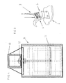
- the substructure 1 is open the bottom 2 of the basin mounted with fastening bolts.
- a guide tube 3 Control system attached to the in the figures.
- the guide tube 3 that in its entirety marked with 4 submersible mixer 4 lowered.
- the submersible mixer is in the operating position 4 on the upper end of the base.
- the substructure 1 is like this high that the rotor blades of the submersible mixer 4 in the completely lowered position do not touch the pelvic floor 2 can.
- Fig. 1 represents a substructure in one-piece embodiment
- the substructure 5 essentially has a drop-shaped one Cross section on.
- the semi-conical end of the base 5 is arranged in the direction of the upstream side in the basin.
- the Inflow is marked with arrow 6.
- the end 7 is fluidically arranged around the pre-twist on the upstream side so that the between the rotor blades of the submersible mixer and the base 5 occurring turbulence can be largely avoided.
- Substructure in which the substructure 8 consists of two Supports 9 is formed, which have a circular cross section. These supports 9 are cast using tubes Service. The z. B. PVC pipes can be special easily removed after pouring the concrete. On on the top of the supports 9 arranged cross member 10 transmits the forces acting on the guide tube 3 on both Supports 9.
- the assembly of the cross member 10 on the front support 9 is special can be seen well from FIG. 4.
- a steel anchor 11 is cast in, one from the support 9 protruding threaded bolt 12.
- a nut of the cross member 10 on this threaded bolt is a nut of the cross member 10 in a known manner and Fastenable way. In this way, the guide tube 3rd simply change by loosening the nuts.
- 5 and 6 represent differently constructed substructures of one-piece construction. In the figures that is Submersible mixer removed. However, are clear in all figures the threaded bolts 13 cast in the concrete are visible.
- Fig. 6 shows an embodiment in which the tapered end of the substructure at an angle to the central longitudinal axis of the substructure 14 has a extending nose 15 which is cast in one piece on the substructure.
- This nose 15 causes a corresponding redirection of the flow.
- geometrical Design of the nose can have different flow conditions depending on the application.
- the vibration damping properties of the Under construction instead of concrete, for example be cast from steel.
- the invention further relates to a substructure for a submersible mixer with rotor blades, especially for use in mixing and aeration tanks or pump sumps or the like, with a bottom that can be placed on a pelvic floor and an upper surface on which a substantially vertical Guide element for the submersible mixer can be attached is, the base is high enough to support of the submersible mixer on the top to prevent the rotor blades with the pelvic floor, the invention is designed so that the substructure is fluidically has favorable shape to the pre-twist on the To reduce the upstream side of the submersible mixer.
- This fluidic improvement can be achieved, for example can be easily achieved that between the Steel pipes of the substructure from the prior art in the direction of flow running metal plates are attached.
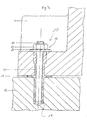
- the substructure 5 can by means of Composite adhesive anchors 16 attached to the bottom 17 of the pool 2 his.
- an anchor rod is designated, which is preferably is designed as a threaded rod and in an anchor hole the bottom 17 is inserted and a mounting hole 20th of the substructure 1 penetrated.
- a balancing mass is referred to before creation the anchor hole 19 introduced into the mounting hole 20 has been.
- the flowability of the leveling compound is adjusted so that the joint 22 between the substructure 1 and the Fills floor 17.
- the leveling compound hardens there is the joint 22 sealed and the anchor hole 19 can then Continuous annulus forming in the mounting hole 20th to be brought down.
- the balancing mass 21 can also be used as a plastic mass Pressure has been introduced into the mounting hole 20.
- a mortar cartridge used in this, for example in the form of a mortar and Plastic hose containing hardener.
- the mortar cartridge is selected in length so that this is both the anchor hole 19 and the mounting hole 20 fills.
- the mortar cartridge destroyed so that the mortar mixes with a hardener and a mortar 23 of the anchor rod 18 almost over their entire length in the anchor hole 19 and in the mounting hole 20 is achieved.
- the substructure 1 is over the Anchor rod 18 with a nut 24 and with a washer 25 and a locking ring 26 against the floor 17th screwed.
Landscapes
- Engineering & Computer Science (AREA)
- General Engineering & Computer Science (AREA)
- Mechanical Engineering (AREA)
- Chemical & Material Sciences (AREA)
- Chemical Kinetics & Catalysis (AREA)
- Physics & Mathematics (AREA)
- Acoustics & Sound (AREA)
- Aviation & Aerospace Engineering (AREA)
- Mixers Of The Rotary Stirring Type (AREA)
- Aeration Devices For Treatment Of Activated Polluted Sludge (AREA)
- Structures Of Non-Positive Displacement Pumps (AREA)
- Mixers With Rotating Receptacles And Mixers With Vibration Mechanisms (AREA)
- Turbine Rotor Nozzle Sealing (AREA)
- Rotary Pumps (AREA)
- Piles And Underground Anchors (AREA)
- Accessories For Mixers (AREA)
Applications Claiming Priority (3)
| Application Number | Priority Date | Filing Date | Title |
|---|---|---|---|
| DE29814958U DE29814958U1 (de) | 1998-08-20 | 1998-08-20 | Unterbau für ein Tauchmotorrührwerk mit Rotorblättern |
| DE29814958U | 1998-08-20 | ||
| EP99113890A EP0980704B1 (fr) | 1998-08-20 | 1999-07-16 | Bâti pour un agitateur à moteur submersible avec de pales rotatives |
Related Parent Applications (1)
| Application Number | Title | Priority Date | Filing Date |
|---|---|---|---|
| EP99113890A Division EP0980704B1 (fr) | 1998-08-20 | 1999-07-16 | Bâti pour un agitateur à moteur submersible avec de pales rotatives |
Publications (3)
| Publication Number | Publication Date |
|---|---|
| EP1406040A2 true EP1406040A2 (fr) | 2004-04-07 |
| EP1406040A3 EP1406040A3 (fr) | 2006-05-17 |
| EP1406040B1 EP1406040B1 (fr) | 2007-04-18 |
Family
ID=8061557
Family Applications (2)
| Application Number | Title | Priority Date | Filing Date |
|---|---|---|---|
| EP99113890A Expired - Lifetime EP0980704B1 (fr) | 1998-08-20 | 1999-07-16 | Bâti pour un agitateur à moteur submersible avec de pales rotatives |
| EP03027655A Expired - Lifetime EP1406040B1 (fr) | 1998-08-20 | 1999-07-16 | Bâti pour un agitateur à moteur submersible avec pales rotatives |
Family Applications Before (1)
| Application Number | Title | Priority Date | Filing Date |
|---|---|---|---|
| EP99113890A Expired - Lifetime EP0980704B1 (fr) | 1998-08-20 | 1999-07-16 | Bâti pour un agitateur à moteur submersible avec de pales rotatives |
Country Status (6)
| Country | Link |
|---|---|
| EP (2) | EP0980704B1 (fr) |
| AT (2) | ATE316419T1 (fr) |
| DE (3) | DE29814958U1 (fr) |
| DK (2) | DK0980704T3 (fr) |
| ES (2) | ES2286374T3 (fr) |
| PT (2) | PT980704E (fr) |
Cited By (2)
| Publication number | Priority date | Publication date | Assignee | Title |
|---|---|---|---|---|
| WO2009079682A1 (fr) * | 2007-12-21 | 2009-07-02 | Sunbeam Corporation Limited | Batteur |
| EP2184099A3 (fr) * | 2008-11-06 | 2011-05-04 | Wilo Se | Dispositif de mélange pour bioréacteurs |
Families Citing this family (3)
| Publication number | Priority date | Publication date | Assignee | Title |
|---|---|---|---|---|
| DE102008050136A1 (de) * | 2008-10-04 | 2010-04-29 | Ksb Aktiengesellschaft | Rührwerksständer |
| DE202016103257U1 (de) | 2016-06-21 | 2017-09-22 | Starrag Gmbh | Einrichtung zur Kühlschmierstoffversorgung für Werkzeugmaschinen |
| DE102016111293B4 (de) | 2016-06-21 | 2018-10-25 | Starrag Gmbh | Einrichtung zur Kühlschmierstoffversorgung für Werkzeugmaschinen |
Family Cites Families (9)
| Publication number | Priority date | Publication date | Assignee | Title |
|---|---|---|---|---|
| US3829540A (en) * | 1970-12-07 | 1974-08-13 | J Cox | Technique for aligning anchor bolts |
| DE2121342A1 (de) * | 1971-04-30 | 1972-11-09 | Motoren-Werke Mannheim AG vorm. Benz Abtstat. Motorenbau, 6800 Mannheim | Schraubenverbindung |
| JPS58219905A (ja) * | 1982-06-12 | 1983-12-21 | Tsukishima Kikai Co Ltd | レ−キ振止め |
| DE3512131A1 (de) * | 1985-04-03 | 1986-10-09 | Hilti Ag, Schaan | Anker zum festlegen in einer aufnahmeoeffnung |
| US4671872A (en) * | 1986-03-18 | 1987-06-09 | Air-O-Lator Corporation | Aerator mast with azimuth lock and bottom stop |
| DE3823163A1 (de) * | 1988-07-08 | 1990-02-01 | Hilti Ag | Ankerstange |
| DE3841577A1 (de) * | 1988-12-09 | 1990-06-13 | Fischer Artur Werke Gmbh | Injektionsadapter mit einem befestigungselement und verfahren zum anbringen eines korrosionsschutzes |
| DE3941724C2 (de) * | 1989-01-11 | 1996-01-11 | Flygt Pumpen Gmbh | Tauchmotorrührwerk für Misch- und Belebungsbecken |
| DE19620986C1 (de) * | 1996-05-24 | 1997-09-25 | Abs Pump Center Gmbh | Einhängevorrichtung |
-
1998
- 1998-08-20 DE DE29814958U patent/DE29814958U1/de not_active Expired - Lifetime
-
1999
- 1999-07-16 DE DE59914306T patent/DE59914306D1/de not_active Expired - Lifetime
- 1999-07-16 ES ES03027655T patent/ES2286374T3/es not_active Expired - Lifetime
- 1999-07-16 DK DK99113890T patent/DK0980704T3/da active
- 1999-07-16 AT AT99113890T patent/ATE316419T1/de not_active IP Right Cessation
- 1999-07-16 EP EP99113890A patent/EP0980704B1/fr not_active Expired - Lifetime
- 1999-07-16 EP EP03027655A patent/EP1406040B1/fr not_active Expired - Lifetime
- 1999-07-16 ES ES99113890T patent/ES2257832T3/es not_active Expired - Lifetime
- 1999-07-16 PT PT99113890T patent/PT980704E/pt unknown
- 1999-07-16 PT PT03027655T patent/PT1406040E/pt unknown
- 1999-07-16 DE DE59913069T patent/DE59913069D1/de not_active Expired - Lifetime
- 1999-07-16 AT AT03027655T patent/ATE359860T1/de not_active IP Right Cessation
- 1999-07-16 DK DK03027655T patent/DK1406040T3/da active
Cited By (2)
| Publication number | Priority date | Publication date | Assignee | Title |
|---|---|---|---|---|
| WO2009079682A1 (fr) * | 2007-12-21 | 2009-07-02 | Sunbeam Corporation Limited | Batteur |
| EP2184099A3 (fr) * | 2008-11-06 | 2011-05-04 | Wilo Se | Dispositif de mélange pour bioréacteurs |
Also Published As
| Publication number | Publication date |
|---|---|
| EP1406040B1 (fr) | 2007-04-18 |
| DE29814958U1 (de) | 1999-01-28 |
| DK1406040T3 (da) | 2007-09-03 |
| EP1406040A3 (fr) | 2006-05-17 |
| EP0980704A3 (fr) | 2002-09-11 |
| DE59913069D1 (de) | 2006-04-13 |
| ATE359860T1 (de) | 2007-05-15 |
| PT980704E (pt) | 2006-06-30 |
| ES2286374T3 (es) | 2007-12-01 |
| DE59914306D1 (de) | 2007-05-31 |
| EP0980704B1 (fr) | 2006-01-25 |
| EP0980704A2 (fr) | 2000-02-23 |
| DK0980704T3 (da) | 2006-06-06 |
| ES2257832T3 (es) | 2006-08-01 |
| PT1406040E (pt) | 2007-07-18 |
| ATE316419T1 (de) | 2006-02-15 |
Similar Documents
| Publication | Publication Date | Title |
|---|---|---|
| EP0014426B1 (fr) | Ancre de roche | |
| DE102005007721B4 (de) | Befestigungs-Anker sowie Anordnung desselben in einem porösen Werkstoff | |
| EP1406040A2 (fr) | Bâti pour un agitateur à moteur submersible avec pales rotatives | |
| EP2159354A1 (fr) | Dispositif de fixation de poteaux pour parois de protection | |
| EP2042657B1 (fr) | Dispositif pour l'ancrage de chaperons sur la superstructure de constructions | |
| DE202009018841U1 (de) | Bohrfundament mit zylindrischem Grundkörper | |
| AT525254B1 (de) | Verankerung eines Bauwerkteils an einem ortsfesten Untergrund | |
| DE3325800A1 (de) | Klebeanker | |
| DE10161426A1 (de) | Verankerung für verspannte Konstruktionen | |
| CH666932A5 (de) | Zug- oder druckstab zur verbindung zweier betonteile. | |
| AT378798B (de) | Sicherung fuer das zur erde abgewinkelte ende von strassenleitschienen | |
| EP3981950A1 (fr) | Système d'ancrage d'un composant à une construction | |
| EP0542692A1 (fr) | Dispositif pour l'ancrage d'éléments de construction dans le sol | |
| EP2507450B1 (fr) | Système d'ancrage de poteaux sur des ouvrages d'art comportant un système de rondelles à portée sphérique et de poulies à cônes | |
| EP1649174A1 (fr) | Dispositif d'ancrage extensible metallique con u pour des materiaux de construction tendres ou poreux | |
| DE102009039337B4 (de) | Betonbauwerk | |
| DE102011056105B4 (de) | Montagezusatzelement für die Befestigung von Bauelementen, z.B. Kellerlichtschächten an Gebäudewänden | |
| DE10258435B4 (de) | Verankerungselement | |
| DE102004015772B4 (de) | Verbindungselement aus Stahl | |
| DE102015213869A1 (de) | Verstärkungselement zum Verstärken eines Bauelements, Verstärkungsanordnung umfassend ein derartiges Verstärkungselement sowie Verfahren zum Verstärken eines Bauelements | |
| DE102022117351A1 (de) | Befestigung von Konsolen in wenig druckfesten Wänden | |
| DE102010022116A1 (de) | Höhenverstellbares Auflager | |
| EP1176321A1 (fr) | Système d'ancrage | |
| DE202019104671U1 (de) | Metalldübel | |
| DE202009010460U1 (de) | Fundament für Grabmale mit einem Keil-Spann-Befestigungssystem |
Legal Events
| Date | Code | Title | Description |
|---|---|---|---|
| PUAI | Public reference made under article 153(3) epc to a published international application that has entered the european phase |
Free format text: ORIGINAL CODE: 0009012 |
|
| 17P | Request for examination filed |
Effective date: 20031203 |
|
| AC | Divisional application: reference to earlier application |
Ref document number: 0980704 Country of ref document: EP Kind code of ref document: P |
|
| AK | Designated contracting states |
Kind code of ref document: A2 Designated state(s): AT BE CH CY DE DK ES FI FR GB GR IE IT LI LU MC NL PT SE |
|
| RIN1 | Information on inventor provided before grant (corrected) |
Inventor name: DIRLA, MANFRED Inventor name: TRIMBORN, ROLF Inventor name: BECKER, KLAUS Inventor name: WASSER, WILFRIED |
|
| PUAL | Search report despatched |
Free format text: ORIGINAL CODE: 0009013 |
|
| AK | Designated contracting states |
Kind code of ref document: A3 Designated state(s): AT BE CH CY DE DK ES FI FR GB GR IE IT LI LU MC NL PT SE |
|
| RIC1 | Information provided on ipc code assigned before grant |
Ipc: B01F 7/00 20060101AFI20060328BHEP Ipc: B01F 15/00 20060101ALI20060328BHEP Ipc: F16M 7/00 20060101ALI20060328BHEP |
|
| GRAP | Despatch of communication of intention to grant a patent |
Free format text: ORIGINAL CODE: EPIDOSNIGR1 |
|
| AKX | Designation fees paid |
Designated state(s): AT BE CH CY DE DK ES FI FR GB GR IE IT LI LU MC NL PT SE |
|
| GRAS | Grant fee paid |
Free format text: ORIGINAL CODE: EPIDOSNIGR3 |
|
| GRAA | (expected) grant |
Free format text: ORIGINAL CODE: 0009210 |
|
| AC | Divisional application: reference to earlier application |
Ref document number: 0980704 Country of ref document: EP Kind code of ref document: P |
|
| AK | Designated contracting states |
Kind code of ref document: B1 Designated state(s): AT BE CH CY DE DK ES FI FR GB GR IE IT LI LU MC NL PT SE |
|
| PG25 | Lapsed in a contracting state [announced via postgrant information from national office to epo] |
Ref country code: FI Free format text: LAPSE BECAUSE OF FAILURE TO SUBMIT A TRANSLATION OF THE DESCRIPTION OR TO PAY THE FEE WITHIN THE PRESCRIBED TIME-LIMIT Effective date: 20070418 |
|
| REG | Reference to a national code |
Ref country code: CH Ref legal event code: EP |
|
| REG | Reference to a national code |
Ref country code: IE Ref legal event code: FG4D Free format text: LANGUAGE OF EP DOCUMENT: GERMAN |
|
| REF | Corresponds to: |
Ref document number: 59914306 Country of ref document: DE Date of ref document: 20070531 Kind code of ref document: P |
|
| REG | Reference to a national code |
Ref country code: PT Ref legal event code: SC4A Free format text: AVAILABILITY OF NATIONAL TRANSLATION Effective date: 20070706 |
|
| REG | Reference to a national code |
Ref country code: SE Ref legal event code: TRGR |
|
| GBT | Gb: translation of ep patent filed (gb section 77(6)(a)/1977) |
Effective date: 20070724 |
|
| REG | Reference to a national code |
Ref country code: DK Ref legal event code: T3 |
|
| REG | Reference to a national code |
Ref country code: GR Ref legal event code: EP Ref document number: 20070402234 Country of ref document: GR |
|
| ET | Fr: translation filed | ||
| REG | Reference to a national code |
Ref country code: IE Ref legal event code: FD4D |
|
| REG | Reference to a national code |
Ref country code: ES Ref legal event code: FG2A Ref document number: 2286374 Country of ref document: ES Kind code of ref document: T3 |
|
| BERE | Be: lapsed |
Owner name: ABS PUMP CENTER G.M.B.H. Effective date: 20070731 |
|
| PG25 | Lapsed in a contracting state [announced via postgrant information from national office to epo] |
Ref country code: IE Free format text: LAPSE BECAUSE OF FAILURE TO SUBMIT A TRANSLATION OF THE DESCRIPTION OR TO PAY THE FEE WITHIN THE PRESCRIBED TIME-LIMIT Effective date: 20070418 |
|
| PLBE | No opposition filed within time limit |
Free format text: ORIGINAL CODE: 0009261 |
|
| STAA | Information on the status of an ep patent application or granted ep patent |
Free format text: STATUS: NO OPPOSITION FILED WITHIN TIME LIMIT |
|
| REG | Reference to a national code |
Ref country code: CH Ref legal event code: PL |
|
| 26N | No opposition filed |
Effective date: 20080121 |
|
| PG25 | Lapsed in a contracting state [announced via postgrant information from national office to epo] |
Ref country code: CH Free format text: LAPSE BECAUSE OF NON-PAYMENT OF DUE FEES Effective date: 20070731 Ref country code: LI Free format text: LAPSE BECAUSE OF NON-PAYMENT OF DUE FEES Effective date: 20070731 Ref country code: MC Free format text: LAPSE BECAUSE OF NON-PAYMENT OF DUE FEES Effective date: 20070731 |
|
| PG25 | Lapsed in a contracting state [announced via postgrant information from national office to epo] |
Ref country code: BE Free format text: LAPSE BECAUSE OF NON-PAYMENT OF DUE FEES Effective date: 20070731 |
|
| PG25 | Lapsed in a contracting state [announced via postgrant information from national office to epo] |
Ref country code: AT Free format text: LAPSE BECAUSE OF NON-PAYMENT OF DUE FEES Effective date: 20070716 |
|
| PG25 | Lapsed in a contracting state [announced via postgrant information from national office to epo] |
Ref country code: CY Free format text: LAPSE BECAUSE OF FAILURE TO SUBMIT A TRANSLATION OF THE DESCRIPTION OR TO PAY THE FEE WITHIN THE PRESCRIBED TIME-LIMIT Effective date: 20070418 |
|
| PG25 | Lapsed in a contracting state [announced via postgrant information from national office to epo] |
Ref country code: LU Free format text: LAPSE BECAUSE OF NON-PAYMENT OF DUE FEES Effective date: 20070716 |
|
| REG | Reference to a national code |
Ref country code: DE Ref legal event code: R082 Ref document number: 59914306 Country of ref document: DE Representative=s name: PATENTANWAELTE LIPPERT, STACHOW & PARTNER, DE Effective date: 20130219 Ref country code: DE Ref legal event code: R081 Ref document number: 59914306 Country of ref document: DE Owner name: SULZER PUMP SOLUTIONS GERMANY GMBH, DE Free format text: FORMER OWNER: ABS PUMP CENTER GMBH, 53797 LOHMAR, DE Effective date: 20130219 Ref country code: DE Ref legal event code: R082 Ref document number: 59914306 Country of ref document: DE Representative=s name: KEMPKENS, ANKE, DE Effective date: 20130219 Ref country code: DE Ref legal event code: R081 Ref document number: 59914306 Country of ref document: DE Owner name: SULZER MANAGEMENT AG, CH Free format text: FORMER OWNER: ABS PUMP CENTER GMBH, 53797 LOHMAR, DE Effective date: 20130219 |
|
| REG | Reference to a national code |
Ref country code: FR Ref legal event code: PLFP Year of fee payment: 17 |
|
| REG | Reference to a national code |
Ref country code: DE Ref legal event code: R082 Ref document number: 59914306 Country of ref document: DE Representative=s name: KEMPKENS, ANKE, DE Ref country code: DE Ref legal event code: R081 Ref document number: 59914306 Country of ref document: DE Owner name: SULZER MANAGEMENT AG, CH Free format text: FORMER OWNER: SULZER PUMP SOLUTIONS GERMANY GMBH, 53797 LOHMAR, DE |
|
| REG | Reference to a national code |
Ref country code: GB Ref legal event code: 732E Free format text: REGISTERED BETWEEN 20160317 AND 20160323 |
|
| REG | Reference to a national code |
Ref country code: PT Ref legal event code: PC4A Owner name: , CH Effective date: 20160412 |
|
| REG | Reference to a national code |
Ref country code: FR Ref legal event code: PLFP Year of fee payment: 18 |
|
| PGFP | Annual fee paid to national office [announced via postgrant information from national office to epo] |
Ref country code: NL Payment date: 20160720 Year of fee payment: 18 |
|
| REG | Reference to a national code |
Ref country code: NL Ref legal event code: HC Owner name: SULZER PUMPS GRUNDBESITZ GERMANY GMBH; DE Free format text: DETAILS ASSIGNMENT: VERANDERING VAN EIGENAAR(S), VERANDERING VAN NAAM VAN DE EIGENAAR(S); FORMER OWNER NAME: CARDO GRUNDBESITZ GMBH Effective date: 20160825 Ref country code: NL Ref legal event code: PD Owner name: SULZER MANAGEMENT AG; CH Free format text: DETAILS ASSIGNMENT: VERANDERING VAN EIGENAAR(S), OVERDRACHT; FORMER OWNER NAME: SULZER PUMPS GRUNDBESITZ GERMANY GMBH Effective date: 20160825 |
|
| PGFP | Annual fee paid to national office [announced via postgrant information from national office to epo] |
Ref country code: GB Payment date: 20160721 Year of fee payment: 18 Ref country code: IT Payment date: 20160725 Year of fee payment: 18 Ref country code: DE Payment date: 20160722 Year of fee payment: 18 Ref country code: DK Payment date: 20160720 Year of fee payment: 18 |
|
| PGFP | Annual fee paid to national office [announced via postgrant information from national office to epo] |
Ref country code: FR Payment date: 20160721 Year of fee payment: 18 Ref country code: PT Payment date: 20160715 Year of fee payment: 18 Ref country code: GR Payment date: 20160720 Year of fee payment: 18 Ref country code: SE Payment date: 20160720 Year of fee payment: 18 |
|
| REG | Reference to a national code |
Ref country code: FR Ref legal event code: CD Owner name: SULZER MANAGEMENT AG, CH Effective date: 20161122 Ref country code: FR Ref legal event code: TP Owner name: SULZER MANAGEMENT AG, CH Effective date: 20161122 |
|
| PGFP | Annual fee paid to national office [announced via postgrant information from national office to epo] |
Ref country code: ES Payment date: 20160715 Year of fee payment: 18 |
|
| REG | Reference to a national code |
Ref country code: DE Ref legal event code: R119 Ref document number: 59914306 Country of ref document: DE |
|
| REG | Reference to a national code |
Ref country code: DK Ref legal event code: EBP Effective date: 20170731 |
|
| REG | Reference to a national code |
Ref country code: NL Ref legal event code: MM Effective date: 20170801 |
|
| REG | Reference to a national code |
Ref country code: SE Ref legal event code: EUG |
|
| GBPC | Gb: european patent ceased through non-payment of renewal fee |
Effective date: 20170716 |
|
| REG | Reference to a national code |
Ref country code: FR Ref legal event code: ST Effective date: 20180330 |
|
| PG25 | Lapsed in a contracting state [announced via postgrant information from national office to epo] |
Ref country code: NL Free format text: LAPSE BECAUSE OF NON-PAYMENT OF DUE FEES Effective date: 20170801 Ref country code: GB Free format text: LAPSE BECAUSE OF NON-PAYMENT OF DUE FEES Effective date: 20170716 Ref country code: DE Free format text: LAPSE BECAUSE OF NON-PAYMENT OF DUE FEES Effective date: 20180201 Ref country code: SE Free format text: LAPSE BECAUSE OF NON-PAYMENT OF DUE FEES Effective date: 20170717 |
|
| PG25 | Lapsed in a contracting state [announced via postgrant information from national office to epo] |
Ref country code: FR Free format text: LAPSE BECAUSE OF NON-PAYMENT OF DUE FEES Effective date: 20170731 Ref country code: PT Free format text: LAPSE BECAUSE OF NON-PAYMENT OF DUE FEES Effective date: 20180116 Ref country code: GR Free format text: LAPSE BECAUSE OF NON-PAYMENT OF DUE FEES Effective date: 20180208 |
|
| PG25 | Lapsed in a contracting state [announced via postgrant information from national office to epo] |
Ref country code: DK Free format text: LAPSE BECAUSE OF NON-PAYMENT OF DUE FEES Effective date: 20170731 |
|
| PG25 | Lapsed in a contracting state [announced via postgrant information from national office to epo] |
Ref country code: IT Free format text: LAPSE BECAUSE OF NON-PAYMENT OF DUE FEES Effective date: 20170716 |
|
| REG | Reference to a national code |
Ref country code: ES Ref legal event code: FD2A Effective date: 20181029 |
|
| PG25 | Lapsed in a contracting state [announced via postgrant information from national office to epo] |
Ref country code: ES Free format text: LAPSE BECAUSE OF NON-PAYMENT OF DUE FEES Effective date: 20170717 |