EP1406074A2 - Dickschicht-Dehnungsmessstreifen aufgebracht auf eine Zündkerze - Google Patents
Dickschicht-Dehnungsmessstreifen aufgebracht auf eine Zündkerze Download PDFInfo
- Publication number
- EP1406074A2 EP1406074A2 EP03077908A EP03077908A EP1406074A2 EP 1406074 A2 EP1406074 A2 EP 1406074A2 EP 03077908 A EP03077908 A EP 03077908A EP 03077908 A EP03077908 A EP 03077908A EP 1406074 A2 EP1406074 A2 EP 1406074A2
- Authority
- EP
- European Patent Office
- Prior art keywords
- voltage output
- engine cylinder
- thick film
- change
- amplifier
- Prior art date
- Legal status (The legal status is an assumption and is not a legal conclusion. Google has not performed a legal analysis and makes no representation as to the accuracy of the status listed.)
- Granted
Links
Images

Classifications
-
- G—PHYSICS
- G01—MEASURING; TESTING
- G01L—MEASURING FORCE, STRESS, TORQUE, WORK, MECHANICAL POWER, MECHANICAL EFFICIENCY, OR FLUID PRESSURE
- G01L23/00—Devices or apparatus for measuring or indicating or recording rapid changes, such as oscillations, in the pressure of steam, gas, or liquid; Indicators for determining work or energy of steam, internal-combustion, or other fluid-pressure engines from the condition of the working fluid
- G01L23/08—Devices or apparatus for measuring or indicating or recording rapid changes, such as oscillations, in the pressure of steam, gas, or liquid; Indicators for determining work or energy of steam, internal-combustion, or other fluid-pressure engines from the condition of the working fluid operated electrically
- G01L23/18—Devices or apparatus for measuring or indicating or recording rapid changes, such as oscillations, in the pressure of steam, gas, or liquid; Indicators for determining work or energy of steam, internal-combustion, or other fluid-pressure engines from the condition of the working fluid operated electrically by resistance strain gauges
-
- G—PHYSICS
- G01—MEASURING; TESTING
- G01L—MEASURING FORCE, STRESS, TORQUE, WORK, MECHANICAL POWER, MECHANICAL EFFICIENCY, OR FLUID PRESSURE
- G01L23/00—Devices or apparatus for measuring or indicating or recording rapid changes, such as oscillations, in the pressure of steam, gas, or liquid; Indicators for determining work or energy of steam, internal-combustion, or other fluid-pressure engines from the condition of the working fluid
- G01L23/22—Devices or apparatus for measuring or indicating or recording rapid changes, such as oscillations, in the pressure of steam, gas, or liquid; Indicators for determining work or energy of steam, internal-combustion, or other fluid-pressure engines from the condition of the working fluid for detecting or indicating knocks in internal-combustion engines; Units comprising pressure-sensitive members combined with ignitors for firing internal-combustion engines
Definitions
- the present invention relates generally to strain gauges and more specifically to a spark plug mounted thick film strain gauge that allows the pressure in an engine cylinder to be monitored.
- a strain gauge mounted to a spark plug shell yields an excellent representation of the engine cylinder pressure with high signal-to-noise ratio.
- commercial strain gauges have a gauge factor of approximately 2.
- a gauge factor of 2 will provide a typical signal level of only a few microvolts.
- Using a commercially available strain gauge would require a very high degree of amplification.
- Strain gauges fabricated from thick-film resistors have gauge factors of between 10 to 20, which produces a signal level which is 5 to 10 times greater than commercially available strain gauges.
- the present invention is a spark plug mounted thick film strain gauge which requires less amplification than that of the prior art.
- the thick film strain gauge is applied to a metal (ie., stainless steel) shell of a spark plug.
- a thick film strain gauge may be directly printed onto the metal shell with special screen printing equipment. Each layer of the thick film resistor is printed, allowed to dry, and fired in a kiln to fix the ink to the metal shell, or the previous layer.
- a thick film resistor is printed and applied as a decal to the metal shell. The spark plug is then fired in a kiln to fix the thick film resistor to the metal shell.
- the thick film resistors may be included in a quarter, a half, or a full wheatstone bridge strain gauge circuit.
- a single thick film resistor is used in a quarter wheatstone bridge circuit; two thick film resistors are used in a half wheatstone bridge circuit; and four thick film resistors are used in a full wheatstone bridge circuit.
- the full wheatstone bridge circuit offers a signal output which is multiplied by as much as four times, and the half wheatstone bridge circuit offers a signal output which is multiplied by as much as two times, the output of the quarter wheatsone bridge circuit. With a full wheatstone bridge circuit, four thick film resistors must be applied to the metal shell.
- An automatic drift compensating circuit is used to monitor the change in resistance experienced by the thick film resistors affixed to the spark plug.
- the automatic drift compensating circuit includes an input amplifier, a compensating amplifier and an output amplifier.
- the output of the wheatstone bridge circuit is input to the input amplifier.
- the output of the input amplifier is input to the compensation amplifier.
- the output of the input amplifier and the compensation amplifier is input to the output amplifier.
- the output amplifier outputs a voltage signal which is proportional to the pressure changes occurring inside the engine cylinder into which the spark plug has been threaded.
- a second embodiment of an automatic drift compensating circuit includes a first input amplifier, a second input amplifier, and an output amplifier.
- the output of the wheatstone bridge circuit is input into the first and second input amplifiers.
- the outputs of the first and second input amplifier are input into the output amplifier.
- Figure 1 shows an axial cross-sectional view of a spark plug 10 with a thick film strain gauge 12 attached to a metal (ie., stainless steel) shell 14 thereof.
- the spark plug 10 further has a ceramic cylinder 16 which locates a positive electrode.
- the metal shell 14 tightly engirds a portion of the ceramic cylinder 16, wherein a threaded portion of the metal shell carries the negative electrode.
- a thick film strain gauge 12 there are two preferable ways of applying a thick film strain gauge 12 to the metal shell 14.
- one or more thick film resistors may be directly printed on to the metal shell 14 with special screen printing equipment.
- the thick film resistors are formed on the metal shell 14 by the following process. Firstly, two dielectric layers are printed, dried, and fired on the metal shell 14. Then, a conductor layer is printed, dried, and fired on the last dielectric layer. Finally, a piezoresistor ink is printed, dried, and fired on the conductor layer.
- at least one thick film resistor is printed and applied as a decal to the metal shell 14. The spark plug is then fired in a kiln to fix the thick film resistor to the metal shell.
- two axial thick film resistors 18a and two hoop thick film resistors 18b are affixed to the metal shell 14, using one or the other of the above affixment methods.
- the two axial thick film resistors 18a measure axial strain of the spark plug 10 induced by engine cylinder combustion pressure.
- the two hoop thick film resistors 18b measure hoop strain of the spark plug 10 induced by engine cylinder combustion pressure.
- the two axial and hoop thick film resistors are respectively shown in Figure 2 as being mutually opposed. However, the position of the thick film resistors on the metal shell 14, or the relative position of the thick film resistors with respect to each other, is depicted merely by way of example and not by way of limitation. Further, four axial thick film resistors may also be used instead having two axial thick film resistors and two hoop thick film resistors.
- the thick film resistors may be included in a quarter, a half, or a full wheatstone bridge strain gauge circuit. While it is obvious, it is instructive to point out that in the wheatstone bridge circuit, only the thick film resistors serve as strain transducers, the regular resistors not serving as strain transducers and are used to balance the quarter and half wheatstone bridge circuits.
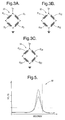
- a quarter wheatstone bridge circuit 20 is depicted at Figure 3A, and includes three regular resistors R 1 , R 2 , R 3 and one thick film resistor G 1 .
- a half wheatstone bridge circuit 22 is depicted at Figure 3B, and includes two regular resistors R 11 , R 12 and two thick film resistors G 11 , G 12 .
- a full wheatstone bridge circuit 24 is depicted at Figure 3C, and includes four thick film resistors G 21 , G 22 , G 23 , G 24 .
- the wheatstone full bridge circuit 24 offers a signal output which is multiplied by as much as four times, and the half wheatstone bridge circuit 22 offers a signal output which is multiplied by as much as two times, over that of the quarter wheatstone bridge circuit 20.
- the full wheatstone bridge circuit involves affixment of four thick film resistors to the spark plug 10.
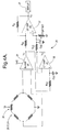
- An automatic drift compensating circuit 26, shown at Figure 4A, is used to determine the change in resistance experienced by the thick film resistors affixed to the spark plug 10 due to strain.
- the thick film resistors are part of a quarter, half or full wheatsone bridge ciruit 20, 22, 24, as described above.
- the automatic drift compensating circuit 26 includes an input amplifier 28, a compensating amplifier 30, and an output amplifier 32.
- the voltage input V s to the wheatsone bridge circuit is adjusted by a potentiometer 36.
- the output of a quarter, half, or full wheatstone bridge 20, 22, 24 is input to the input amplifier 28 which is in the form of an instrumentation amplifier, which generally consists of two or three operational amplifiers in a manner which is well known in the art.
- the output of the input amplifier 28 is input to the compensation amplifier 30 and the output amplifier 32.
- the input amplifier is supplied with a reference voltage V s /2 which establishes a quiescent output voltage of the input amplifier as equal to V s /2.
- the compensation amplifier 30 is configured as a unity-gain follower. Voltage V 1 is input to the compensation amplifier 30 and filtered by resistor R 01 and capacitor C 01 .
- the compensation amplifier 30 outputs a voltage V 2 which is input to the positive terminal of the output amplifier 32.
- the voltage V 2 is filtered by resistor R 02 and capacitor C 02 .
- the output amplifier 32 is configured as a differential amplifier.
- the voltage V 1 is input to the negative terminal of the output amplifier 32 through input resistor R in .
- Gain resistor R g provides the output amplifier 32 with an output voltage of V 3 .
- the variation in voltage signal is used, such as for example via a display 38 (ie., a memory oscilloscope) to monitor the pressure readings inside the engine cylinder without having a pressure sensor penetrating the cylinder.
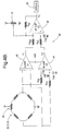
- a second embodiment of an automatic drift compensating circuit 40 may also be used to determine the change in resistance experienced by the thick film resistors affixed to the spark plug 10 due to strain.
- the thick film resistors are part of the quarter, half or full wheatsone bridge circuit 20, 22, 24, as described above.
- the automatic drift compensating circuit 40 includes a first input amplifier 42, a second input amplifier 44, and an output amplifier 46. The voltage input V s to the wheatsone bridge circuit is adjusted by the potentiometer 36.
- the output of the quarter, half, or full wheatstone bridge 20, 22, 24 is input into the first input amplifier 42 and the second input amplifier 44 which are both in the form of an instrumentation amplifier, which generally consists of two or three operational amplifiers in a manner which is well known in the art.
- One input terminal of the second input amplifier 44 is filtered with resistor R 03 and capacitor C 03 and the other input terminal is filtered with resistor R 04 and capacitor C 04 .
- the first and second input amplifiers are supplied with a reference voltage V s /2 which establishes a quiescent output voltage of the input amplifiers as equal to V s /2.
- a negative terminal of the output amplifier 46 is supplied by the output of the first input amplifier 42 through a resistor R in2 .
- the voltage V 2 ' is filtered by resistor R 05 and capacitor C 05 .
- a positive terminal of the output amplifier 46 is supplied by the output of the second input amplifier 44 and voltage V s through offset potentiometer 48.
- the output amplifier 46 is configured as a differential amplifier.
- Gain resistor R g2 provides the output amplifier 46 with an output voltage of V 3 .
- the variation in voltage signal is used, such as for example via a display 38 (ie., a memory oscilloscope) to monitor the pressure readings inside the engine cylinder without having a pressure sensor penetrating the cylinder.
- Figure 5 depicts an example of a graphical output 50 of a display showing a combustion event, wherein the spark plug has a half wheatstone bridge circuit according to the present invention.
- the vertical axis is in volts, which corresponds to cylinder pressure (ie., psi, bars, etc.), and the horizontal axis is in seconds, which corresponds to crank angle at constant engine speed.
Landscapes
- Chemical & Material Sciences (AREA)
- Engineering & Computer Science (AREA)
- Combustion & Propulsion (AREA)
- Physics & Mathematics (AREA)
- General Physics & Mathematics (AREA)
- Ignition Installations For Internal Combustion Engines (AREA)
- Measuring Fluid Pressure (AREA)
Applications Claiming Priority (2)
| Application Number | Priority Date | Filing Date | Title |
|---|---|---|---|
| US264068 | 2002-10-03 | ||
| US10/264,068 US6679100B2 (en) | 2001-03-05 | 2002-10-03 | Spark plug mounted thick film strain gauge |
Publications (3)
| Publication Number | Publication Date |
|---|---|
| EP1406074A2 true EP1406074A2 (de) | 2004-04-07 |
| EP1406074A3 EP1406074A3 (de) | 2005-06-29 |
| EP1406074B1 EP1406074B1 (de) | 2007-09-05 |
Family
ID=31993577
Family Applications (1)
| Application Number | Title | Priority Date | Filing Date |
|---|---|---|---|
| EP03077908A Expired - Lifetime EP1406074B1 (de) | 2002-10-03 | 2003-09-15 | Dickschicht-Dehnungsmessstreifen aufgebracht auf eine Zündkerze |
Country Status (3)
| Country | Link |
|---|---|
| US (2) | US6679100B2 (de) |
| EP (1) | EP1406074B1 (de) |
| DE (1) | DE60316084T2 (de) |
Families Citing this family (6)
| Publication number | Priority date | Publication date | Assignee | Title |
|---|---|---|---|---|
| ATE442328T1 (de) * | 2006-12-15 | 2009-09-15 | Texmag Gmbh Vertriebsges | Verfahren zur messung der zugspannung einer laufenden bahn |
| FR2925777B1 (fr) * | 2007-12-21 | 2010-09-17 | Siemens Vdo Automotive | Bougie d'allumage a capteur de pression integre pour moteur a combustion interne |
| EP2392060A4 (de) * | 2009-01-29 | 2012-08-01 | Federal Mogul Ignition Co | Zündkerze mit integriertem verbrennungssensor und maschinenbauteil damit |
| US9429485B1 (en) * | 2015-03-12 | 2016-08-30 | The United States Of America As Represented By The Secretary Of The Navy | Bolt shear force sensor |
| CN110926684A (zh) * | 2019-12-17 | 2020-03-27 | 中国电子科技集团公司第四十九研究所 | 一种耐350℃高温压力传感器的转接环结构 |
| DE102023210374A1 (de) * | 2023-10-20 | 2025-04-24 | Dkt Verwaltungs-Gmbh | Vorkammerzündkerze, Vorrichtung und Verfahren zum Bestimmen mindestens einer Motorbetriebsgröße |
Family Cites Families (23)
| Publication number | Priority date | Publication date | Assignee | Title |
|---|---|---|---|---|
| GB1591620A (en) * | 1976-12-21 | 1981-06-24 | Nat Res Dev | Signal-conditioning circuits |
| JPS58140604A (ja) * | 1982-02-17 | 1983-08-20 | Hitachi Ltd | 温度補償回路付き集積化センサ |
| KR920006455B1 (ko) * | 1988-02-22 | 1992-08-06 | 미쓰비시전기주식회사 | 내연기관의 실린더내 압력검출장치 |
| JPH01134392U (de) * | 1988-03-07 | 1989-09-13 | ||
| JPH0777266B2 (ja) * | 1988-12-28 | 1995-08-16 | 株式会社豊田中央研究所 | 半導体歪み検出装置 |
| US5181417A (en) * | 1989-07-10 | 1993-01-26 | Nippon Soken, Inc. | Pressure detecting device |
| US5187985A (en) * | 1991-09-19 | 1993-02-23 | Honeywell Inc. | Amplified pressure transducer |
| JP3141218B2 (ja) * | 1992-07-28 | 2001-03-05 | 日本特殊陶業株式会社 | 圧力センサ内蔵スパークプラグ |
| US5914593A (en) | 1993-06-21 | 1999-06-22 | Micro Strain Company, Inc. | Temperature gradient compensation circuit |
| JP3346438B2 (ja) * | 1994-05-27 | 2002-11-18 | 株式会社ユニシアジェックス | エンジンの筒内圧検出装置 |
| GB2304812A (en) * | 1995-08-26 | 1997-03-26 | Ford Motor Co | Pressure sensing spark plug |
| US5672812A (en) * | 1995-10-10 | 1997-09-30 | Southwest Research Institute | Sparkplug/pressure sensor device |
| US5712424A (en) | 1996-03-25 | 1998-01-27 | The United States Of America As Represented By The Secretary Of The Navy | Method and apparatus for measuring diesel engine cylinder pressure |
| US5777468A (en) | 1996-12-19 | 1998-07-07 | Texas Instruments Incorporated | Variable differential transformer system and method providing improved temperature stability and sensor fault detection apparatus |
| US5898359A (en) * | 1997-12-19 | 1999-04-27 | Delco Electronics Corp. | Diffusion-barrier materials for thick-film piezoresistors and sensors formed therewith |
| US6094990A (en) * | 1998-06-30 | 2000-08-01 | Cooper Automotive Products, Inc. | Spark plug with concentric pressure sensor |
| GB2344179A (en) * | 1998-11-28 | 2000-05-31 | Ford Global Tech Inc | Spark plug with combustion pressure sensor |
| US6119667A (en) * | 1999-07-22 | 2000-09-19 | Delphi Technologies, Inc. | Integrated spark plug ignition coil with pressure sensor for an internal combustion engine |
| US6378384B1 (en) * | 1999-08-04 | 2002-04-30 | C-Cubed Limited | Force sensing transducer and apparatus |
| US20040083795A1 (en) * | 2001-03-05 | 2004-05-06 | Butler Raymond O. | Pressure sense gauge assembly for attachment to automatic spark plug |
| US6668632B2 (en) * | 2001-03-05 | 2003-12-30 | Delphi Technologies, Inc. | Spark apparatus with pressure signal response amplification |
| US6799451B2 (en) * | 2001-03-05 | 2004-10-05 | Delphi Technologies, Inc. | Spark generating apparatus having strain gage cylinder pressure measurement feature |
| JP2002332908A (ja) * | 2001-05-02 | 2002-11-22 | Ngk Spark Plug Co Ltd | 内燃機関の失火検出方法及び失火検出システム |
-
2002
- 2002-10-03 US US10/264,068 patent/US6679100B2/en not_active Expired - Fee Related
-
2003
- 2003-09-15 DE DE60316084T patent/DE60316084T2/de not_active Expired - Fee Related
- 2003-09-15 EP EP03077908A patent/EP1406074B1/de not_active Expired - Lifetime
- 2003-10-09 US US10/682,664 patent/US6834538B2/en not_active Expired - Fee Related
Also Published As
| Publication number | Publication date |
|---|---|
| DE60316084T2 (de) | 2008-05-29 |
| US20040129059A1 (en) | 2004-07-08 |
| DE60316084D1 (de) | 2007-10-18 |
| US6834538B2 (en) | 2004-12-28 |
| US20030029248A1 (en) | 2003-02-13 |
| EP1406074A3 (de) | 2005-06-29 |
| US6679100B2 (en) | 2004-01-20 |
| EP1406074B1 (de) | 2007-09-05 |
Similar Documents
| Publication | Publication Date | Title |
|---|---|---|
| US8770009B2 (en) | Compensation arrangement and method for operation thereof | |
| EP0640743B1 (de) | Kraftmessdose zur Erfassung des, von auf den Bohrmeissel während des bohrens ausgeübten, Gewichts und Drehmoments | |
| US4420980A (en) | Arrangement for measuring the pressure in cylindrical cavities | |
| US5460049A (en) | Digitally-temperature-compensated strain-gauge pressure measuring apparatus | |
| EP0803054B1 (de) | Methode zur temperaturkompensation für druckwandler | |
| JP2597042B2 (ja) | 差圧測定装置 | |
| EP1286148A1 (de) | Verfahren zum einstellen eines drucksensors | |
| JPH10170370A (ja) | 圧力センサ | |
| KR101537422B1 (ko) | 측정 롤러 및 밴드의 편평도 에러 또는 밴드 장력을 검출하는 방법 | |
| EP1406074B1 (de) | Dickschicht-Dehnungsmessstreifen aufgebracht auf eine Zündkerze | |
| US20180328804A1 (en) | Sensor element for a pressure sensor | |
| US5974898A (en) | Force sensor having test deflection device | |
| JPH09178597A (ja) | 半導体型燃焼圧センサ | |
| CA1309878C (en) | Dual sided pressure sensor | |
| US7343808B2 (en) | Line pressure compensated differential pressure transducer assembly | |
| KR100413093B1 (ko) | 타축감도를 최소화한 압저항형 센서 구조 및 그 센서의제조방법 | |
| JP3329480B2 (ja) | 差圧測定装置 | |
| GB2129565A (en) | Pressure and temperature transducer | |
| US20240200944A1 (en) | Micromechanical rotation rate sensor comprising a sensor element and a method for operating a micromechanical rotation rate sensor comprising a sensor element | |
| JP3082636B2 (ja) | 歪み測定装置 | |
| GB2348958A (en) | Pressure sensitive piezo-resistive transducer | |
| JP2002039888A (ja) | 半導体圧力センサのゲージ抵抗の位置設定方法 | |
| US3303702A (en) | Pressure transducers | |
| JPH05281065A (ja) | 圧力センサ | |
| Hochstoger et al. | Piezoresistive torque sensor realized in thick film on tube technology |
Legal Events
| Date | Code | Title | Description |
|---|---|---|---|
| PUAI | Public reference made under article 153(3) epc to a published international application that has entered the european phase |
Free format text: ORIGINAL CODE: 0009012 |
|
| AK | Designated contracting states |
Kind code of ref document: A2 Designated state(s): AT BE BG CH CY CZ DE DK EE ES FI FR GB GR HU IE IT LI LU MC NL PT RO SE SI SK TR |
|
| AX | Request for extension of the european patent |
Extension state: AL LT LV MK |
|
| PUAL | Search report despatched |
Free format text: ORIGINAL CODE: 0009013 |
|
| AK | Designated contracting states |
Kind code of ref document: A3 Designated state(s): AT BE BG CH CY CZ DE DK EE ES FI FR GB GR HU IE IT LI LU MC NL PT RO SE SI SK TR |
|
| AX | Request for extension of the european patent |
Extension state: AL LT LV MK |
|
| 17P | Request for examination filed |
Effective date: 20051229 |
|
| AKX | Designation fees paid |
Designated state(s): DE FR GB |
|
| 17Q | First examination report despatched |
Effective date: 20060627 |
|
| GRAP | Despatch of communication of intention to grant a patent |
Free format text: ORIGINAL CODE: EPIDOSNIGR1 |
|
| GRAS | Grant fee paid |
Free format text: ORIGINAL CODE: EPIDOSNIGR3 |
|
| GRAA | (expected) grant |
Free format text: ORIGINAL CODE: 0009210 |
|
| AK | Designated contracting states |
Kind code of ref document: B1 Designated state(s): DE FR GB |
|
| REG | Reference to a national code |
Ref country code: GB Ref legal event code: FG4D |
|
| REF | Corresponds to: |
Ref document number: 60316084 Country of ref document: DE Date of ref document: 20071018 Kind code of ref document: P |
|
| ET | Fr: translation filed | ||
| PLBE | No opposition filed within time limit |
Free format text: ORIGINAL CODE: 0009261 |
|
| STAA | Information on the status of an ep patent application or granted ep patent |
Free format text: STATUS: NO OPPOSITION FILED WITHIN TIME LIMIT |
|
| 26N | No opposition filed |
Effective date: 20080606 |
|
| GBPC | Gb: european patent ceased through non-payment of renewal fee |
Effective date: 20071205 |
|
| PGFP | Annual fee paid to national office [announced via postgrant information from national office to epo] |
Ref country code: FR Payment date: 20080915 Year of fee payment: 6 |
|
| PG25 | Lapsed in a contracting state [announced via postgrant information from national office to epo] |
Ref country code: GB Free format text: LAPSE BECAUSE OF NON-PAYMENT OF DUE FEES Effective date: 20071205 |
|
| PGFP | Annual fee paid to national office [announced via postgrant information from national office to epo] |
Ref country code: DE Payment date: 20080926 Year of fee payment: 6 |
|
| REG | Reference to a national code |
Ref country code: FR Ref legal event code: ST Effective date: 20100531 |
|
| PG25 | Lapsed in a contracting state [announced via postgrant information from national office to epo] |
Ref country code: FR Free format text: LAPSE BECAUSE OF NON-PAYMENT OF DUE FEES Effective date: 20090930 Ref country code: DE Free format text: LAPSE BECAUSE OF NON-PAYMENT OF DUE FEES Effective date: 20100401 |