EP1406079A2 - Durchflusszelle - Google Patents
Durchflusszelle Download PDFInfo
- Publication number
- EP1406079A2 EP1406079A2 EP03022052A EP03022052A EP1406079A2 EP 1406079 A2 EP1406079 A2 EP 1406079A2 EP 03022052 A EP03022052 A EP 03022052A EP 03022052 A EP03022052 A EP 03022052A EP 1406079 A2 EP1406079 A2 EP 1406079A2
- Authority
- EP
- European Patent Office
- Prior art keywords
- viewing
- fluid
- aperture
- flow cell
- cell device
- Prior art date
- Legal status (The legal status is an assumption and is not a legal conclusion. Google has not performed a legal analysis and makes no representation as to the accuracy of the status listed.)
- Withdrawn
Links
Images


Classifications
-
- G—PHYSICS
- G01—MEASURING; TESTING
- G01N—INVESTIGATING OR ANALYSING MATERIALS BY DETERMINING THEIR CHEMICAL OR PHYSICAL PROPERTIES
- G01N21/00—Investigating or analysing materials by the use of optical means, i.e. using sub-millimetre waves, infrared, visible or ultraviolet light
- G01N21/01—Arrangements or apparatus for facilitating the optical investigation
- G01N21/03—Cuvette constructions
- G01N21/05—Flow-through cuvettes
Definitions
- the present invention relates generally to fluid inspection systems and particularly to a flow cell device for observing a fluid passing through it.
- the present invention also relates to a method for observing a fluid in a flow cell.
- Various devices have been used for inspecting a fluid inside of process vessels, engines, pipes, hoses, or other fluid-containing receptacles.
- a viewing port on the side of a vessel or pipeline to view its interior.
- Many such viewing ports employ a glass disk bolted to the side of the vessel or pipe in various configurations.
- Structurally superior examples of a viewing unit are disclosed, for example, in U.S. Patent Nos. 4,809,862 and 6,359,742, which are both incorporated by reference herein.
- Other types of window viewing units are described, for example, in U.S. Patent Nos. 2,744,487, 3,299,851, 3,837,226, and 4,245,566.
- Known devices have included fixed aperture cells, or cells having an aperture between two opposing plates in which the aperture can only be adjusted offline.
- these cells consist of two thin glass plates glued together with a gasket therebetween for forming an aperture.
- a bolted assembly of metal plates may be used to retain the thin glass flow cells.
- Such a thin glass plate construction typical of known flow cells, is subject to breakage or leakage.
- the thickness of the aperture is either unchangeable or can only be changed offline (i.e. it must be first be disconnected from the fluid flow), requiring considerable time and effort. The flow and analysis of the process fluid must cease during that time.
- the aperture is typically changed by disassembling the flow cell and replacing the gasket with another gasket of a different thickness. Changing the aperture in these cells not only wastes time, but the selection of aperture thickness is limited by the sizes of the available gaskets.
- U.S. Patent No. 6,104,483 (the "'483 patent") describes a fluid inspection system that includes an optical flow cell for use with an imaging system.
- the optical flow cell described in the '483 patent includes a housing and a pair of two opposing optical plates through which a sample fluid material flows.
- This optical flow cell again has the disadvantage that the gap between the opposing optical plates is not adjustable and is suitable only for observing fluid samples, as in a laboratory environment, not for on-line use in an ongoing industrial process.
- this object according to the invention is achieved with a housing defining an inlet and an outlet and a viewing assembly coupled to the housing.
- the viewing assembly includes a first viewing member adjacent to an aperture that is in fluid communication with the inlet and the outlet.
- the first viewing member is configured to enable a viewing of the fluid in the aperture and is adjustable with respect to the housing so that a thickness of the aperture is variable.
- Precise aperture thickness adjustment is particularly beneficial for improved viewing and measuring of different characteristics of the same or different process fluids. Changing the aperture thickness using different sized gaskets is time consuming, inexact and often not reliably repeatable.
- the optimal aperture for observing a fluid will vary depending on which characteristics of the fluid are desired to be observed at any given time. The optimal aperture will also depend on properties of the fluid and of any suspended particles. Characteristics that may be observed include, among others, the turbidity and color of the fluid, as well as the size, shape, density, opaqueness, and color of the particles.
- the system for observing a fluid provides improved ruggedness, durability, and the capability to handle extreme environments, such as high or low pressures and/or high or low temperatures.
- the viewing assembly may also include a second viewing member disposed opposite the first viewing member and the aperture defined between the first and second viewing members.
- the housing may include a first housing half and a first sealing element which preferably is disposed between the first housing half and the viewing assembly.
- the viewing assembly preferably includes a first adapter member disposed between the first viewing member and the housing.
- the viewing assembly may include a second adapter disposed between the second viewing member and the housing.
- At least one of the first and second viewing members may be configured to enable an illumination of the fluid in the aperture.
- both viewing and illumination can be performed through the first viewing member.
- viewing and illumination can be performed from opposite sides of the aperture.
- At least one of the first and second viewing members may include a viewing port and the other of first and second viewing members may include an illumination port.
- the viewing port and/or illumination port may include a transparent viewing window disposed therein.
- the transparent viewing window is preferably glass and is fused to a metal portion of one of the first and second viewing members.
- the flow cell device may also include a light source coupled to one of the first and second viewing members, which may include a fiber optic bundle, which may be configured to form a ring arrangement, a point arrangement, or a broadly dispersed arrangement at a position adjacent to one of the first and second viewing members.
- a camera may be coupled to the viewing port of the flow cell device.
- the camera may also include a light source to provide illumination to the fluid, for those situations in which direct lighting of the fluid from the same direction as the camera provides optimal imaging.
- a flow path of the fluid preferably includes a rectangular cross-section when the fluid is in the aperture.
- An inlet reservoir in fluid communication with the inlet may also be included in the flow cell.
- the inlet reservoir preferably has a greater volume than a volume of the fluid in the aperture.
- the inlet may be narrower than the thickness of the aperture.
- the viewing assembly is preferably suitable and designed for containing the fluid at a high pressure, for example a pressure up to approximately 413,68 bar.
- a second inlet and or a second outlet in fluid communication with the aperture may be defined in the housing.
- the object identified above is achieved by passing the fluid through an adjustable aperture defined, on one side, by a first viewing member that is moveable so that a thickness of the aperture is adjustable.
- the method also includes viewing the fluid through the first viewing member as the fluid passes through the aperture.
- a second side of the aperture may be defined by a second viewing member so that the fluid passes through the two viewing member.
- the method may also include the step of moving the first viewing member so as to adjust the thickness of the aperture.
- the viewing may be performed using a camera coupled to the first or second viewing member.
- the method may also include illuminating the fluid through either one of the first and second viewing members.
- the illuminating may be performed using a fiber optic bundle, which may be arranged in a ring-shape, coupled to the first or second viewing member.
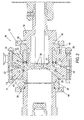
- Fig. 1 shows a partial perspective view of one embodiment of flow cell device 10 according to the present invention.
- Flow cell device 10 includes housing 11, which consists of first housing half 12 joined together with second housing half 13.
- a gasket 47 may be disposed between the two housing halves so as to form housing gap 31 between the first and second housing halves. (See Fig. 2).
- the housing halves may include internal recesses for forming housing gap 31.
- Second housing half 13 includes inlet conduit 14 which is in fluid communication with housing gap 31 between the two housing halves.
- First housing half 12 includes outlet conduit 14 which is likewise in fluid communication with housing gap 31 between the two housing halves.
- Viewing assembly 18 is coupled to housing 11 and includes, in the preferred embodiment first viewing member 26 and second viewing member 28, which are disposed opposite one another so as to form adjustable aperture 23 therebetween, as can be more clearly seen in Fig. 2. It is also recognized that the viewing assembly could include a single viewing member adjustable with respect to the housing and forming an adjustable aperture between the viewing member in the housing. In the preferred embodiment, aperture 23 is formed between viewing members 26 and 28 and is in fluid communication with housing gap 31. However, unlike housing gap 31, aperture 23 is adjustable while the fluid is flowing through the flow cell device, by a moving first viewing member 26 with respect to the housing 11.
- Inlet conduit 14 can be attached, for example using a hose or high pressure pipeline, to an inlet source (not shown).
- the inlet source may be a laboratory vessel containing a sample fluid, or may be an a pipe, engine, or other fluid containing vessel that is integral with an ongoing industrial process.
- outlet conduit 15 can be attached, for example using a hose or high pressure pipeline to an outlet receptacle (not shown).
- the outlet receptacle may be a laboratory vessel for holding a sample fluid, but may also be a pipe, engine, or other fluid-containing vessel that is integral with an ongoing industrial process.
- the flow cell device described in the drawings may be used to observe fluid samples in a laboratory setting, or may be installed on-line to observe fluids directly as they occur during an ongoing industrial process.
- a pump, or other pressure creating device may be used in conjunction with the flow cell device 10, in order to cause the fluid to flow through the device.
- gravity or the fluid pressures inherent in the online process will cause the desired flow.
- Light source 16 may be coupled to first viewing member 26 in order to illuminate the fluid as it flows in the aperture 23. Viewing and illumination can also take place through the same port.
- Light source 16 includes light pipe 19, which, in this embodiment, contains fiber optic bundles that carry the light to first viewing member 26.
- the light source includes an incandescent bulb emitting visible white light.
- the light source may include any of a number of sources for emitting the light including, for example, various types of light bulbs, lasers, light emitting diodes, reflection of ambient light, and light emitting chemical reactions.
- viewing assembly 18 includes first and second viewing members 26, 28.
- the viewing assembly 18 is coupled to first housing half 12 at first viewing assembly opening 41 in housing half 12.
- the viewing assembly 18 includes first adapter element 45 which is coupled to the first housing half 12 with the help of first flange 43, which may be bolted to first housing half 12.
- First sealing element 36 is disposed between first adapter member 45 of viewing assembly 18 and housing half 12 so that fluid may not escape through opening 41.
- Second sealing element 32 is disposed between first viewing member 26 and first adapter member 45.
- the viewing assembly 18 is also coupled to second housing half 13 at second viewing assembly opening 42 in housing half 13.
- the viewing assembly 18 includes a second adapter member 46, which is secured to housing half 13 with the help of second flange 44, which may be bolted to second housing half 13.
- Third sealing element 33 is disposed between second adapter member 46 of viewing assembly 18 and housing half 13 so that fluid may not escape through opening 42.
- light source 16 is coupled to first viewing member 27 to illuminate the fluid in aperture 23 and camera 17 is coupled to second viewing member 28.
- Camera 17 may be any kind of camera, such as, for example, a still camera, a video camera, or a CCD camera, and may transmit the image to a remote location, where it can be observed, for example on a video monitor.
- the image may also be sent as an electronic file to a microprocessor, where various measurements, analysis and calculations are made to the image information.
- viewing could be performed with or without instrumentation such as a camera from either or both viewing elements.
- illumination of the fluid could be performed, through either or both of the viewing elements, or with no special lighting apparatus, such as allowing ambient light to shine through one or both of the viewing members.
- both members 26 and 28 are referred to as viewing members, it is not necessary that both members enable a viewing of the fluid.
- viewing member 28 enables a viewing of the fluid through camera 17, and viewing member 26 enables an illumination of the fluid using light source 16. It is also not necessary that the two viewing members enable either viewing or illumination.
- one viewing member may be made of solid steel and enable neither, such that viewing and/or viewing and illumination are carried out through the other viewing member.
- first and second viewing members 26, 28 each define viewing ports 27 and 29 respectively. Disposed within each viewing port is a transparent glass window 35 to allow illumination and or viewing of the fluid in aperture 23.
- the surface of each window toward the aperture is preferably flush with a surface of the respective viewing member 26, 28.
- the glass windows 35 are preferably fused directly to an annular metal frame, for example as described in U.S. Patent No. 6,359,742.
- the glass windows 35 can be directly to a metal end portion of the respective viewing member 26, 28, shaped to form an annular frame.
- the construction is sturdy enough to handle fluids having high pressures, such as pressures of up to approximately 413,68 bar (corresponding to 6000 psi).
- the sturdy fused glass to metal construction enables a wide field of view for a broader view of the flow stream and thus better analytical accuracy, and a larger flow cell to process more fluid in less time.
- the sturdy construction also enables the device to be employed in rugged field environments, such as when vibration and other ambient effects are present that might cause a thin glass window flow cell to leak or break.
- first viewing member 26 is adjustable with respect to the second viewing member 28 so as to vary a thickness t , of aperture 23.
- First adapter member 45 and first viewing member each include a corresponding threaded area 34.
- the adjustment can be performed while the fluid is flowing through the device 10, and while viewing the fluid in aperture 23.
- the threading allows very precise positioning of the viewing member 26, and thus very exact sizing of thickness t of aperture.
- the second viewing member is fixedly attached to the second adapter member 46, which is fixedly attached to second housing half 13.
- the flow cell could alternatively be constructed so that the second viewing member was adjustable instead, or so that both the first and second viewing members were adjustable, or with a single viewing member forming an adjustable aperture between the single viewing member and a wall of the housing.
- the adjustment mechanism for the viewing members may also be automatic. For example, the position of the viewing members could be cycled to form first a narrow then wide aperture so as to capture particles of interest between the viewing members for viewing, then releasing them and capturing a new volume of sample.
- the adjustment mechanism may also be controllable from a remote location, such as from a monitoring control room.
- the surfaces of the viewing members and glas windows are preferably flat and parallel at the aperture 23. This provides a flow stream that is of constant thickness and the fluid remains a constant distance from a viewing apparatus such as camera 17. This can be important for gathering accurate and consistent measurements. For example, when measuring particle size, two particles of the same size at significantly different distances from the viewing means may appear to have different sizes.
- Fig. 3 shows a front view of second housing half 13 without the rest of the flow cell device 10.
- inlet conduit connects to inlet reservoir 21, which is a space in the interior portion of housing half 13.
- a second inlet 14 also joins inlet reservoir 14a.
- Two (or more) inlet conduits can be used in order to allow fluids from two different sources to be analyzed, with the two fluids mixing in reservoir 13 just before passing through inlet 22 into housing gap 31. This may be useful, for example for time-sensitive or atmospheric-sensitive characteristics of fluid mixtures, which would be difficult to view if they had to be mixed in advance.
- the volume of inlet reservoir 24 is greater than the volume between housing halves 12 and 13 (i.e. the volume of the fluid in housing gap 31 and aperture 23).
- a long thin inlet opening 22 is preferable to provide an even flow field across the width of the flow cell.
- Second housing half 13 defines second viewing assembly opening 41, inside which the viewing assembly 18 may be disposed.
- Fig. 4 shows a front view of first housing half 12, which includes first viewing assembly opening 42 inside of which the viewing assembly 18 may be disposed. Opening 42 is positioned in a central region of first housing half 12 so that it aligns across from second viewing member opening 41, when the two housing halves are joined together. After flowing through aperture 23, the fluid flows out of outlet 24 into outlet reservoir 25. The fluid may then flow out either or both of outlet conduit 15 and second outlet conduit 15a.
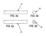
- Figs. 5a and 5b show side and end views of fiber optic bundle 51.
- Reference numeral 51 refers to a standard fiber optic bundle in which the fibers are generally evenly distributed in a cylindrical form.
- the end 52 of the standard fiber optic bundle is forms a circle of light.
- the end of the fiber optic bundle is preferably placed adjacent one of the viewing members in order to illuminate the fluid in the aperture.
- Fig. 6a and 6b show a ring fiber optic bundle in which the fibers are arranged in a ring shape in an outer area of a cylinder.
- the end 62 of ring fiber optic bundle 61 forms a ring of light.
- the inventors have discovered that this formation provides light into the flow cell at an angle, which allows particles in the fluid to be illuminated by partial side light. In many cases, partial side lighting creates better visibility of the particles.
Landscapes
- Physics & Mathematics (AREA)
- Health & Medical Sciences (AREA)
- Life Sciences & Earth Sciences (AREA)
- Chemical & Material Sciences (AREA)
- Analytical Chemistry (AREA)
- Biochemistry (AREA)
- General Health & Medical Sciences (AREA)
- General Physics & Mathematics (AREA)
- Immunology (AREA)
- Pathology (AREA)
- Optical Measuring Cells (AREA)
- Investigating Or Analysing Materials By Optical Means (AREA)
Applications Claiming Priority (2)
| Application Number | Priority Date | Filing Date | Title |
|---|---|---|---|
| US264858 | 1988-10-31 | ||
| US10/264,858 US6771366B2 (en) | 2002-10-04 | 2002-10-04 | Fluid flow cell |
Publications (2)
| Publication Number | Publication Date |
|---|---|
| EP1406079A2 true EP1406079A2 (de) | 2004-04-07 |
| EP1406079A3 EP1406079A3 (de) | 2005-02-16 |
Family
ID=31993591
Family Applications (1)
| Application Number | Title | Priority Date | Filing Date |
|---|---|---|---|
| EP03022052A Withdrawn EP1406079A3 (de) | 2002-10-04 | 2003-10-01 | Durchflusszelle |
Country Status (2)
| Country | Link |
|---|---|
| US (1) | US6771366B2 (de) |
| EP (1) | EP1406079A3 (de) |
Cited By (5)
| Publication number | Priority date | Publication date | Assignee | Title |
|---|---|---|---|---|
| EP1764608A3 (de) * | 2005-09-16 | 2007-05-02 | Lockheed Martin Corporation | Optische Durchflusszelle zur Verwendung in Umgebungen mit hohen Temperaturen und hohem Druck |
| WO2009062667A1 (de) * | 2007-11-13 | 2009-05-22 | Roche Diagnostics Gmbh | Küvette und verfahren zur verwendung der küvette |
| EP1994392A4 (de) * | 2006-03-10 | 2009-07-15 | Dionex Corp | Durchflusszelle für optischen detektor sowie verfahren zur herstellung davon |
| ITRM20110029A1 (it) * | 2011-01-25 | 2012-07-26 | Enea Agenzia Naz Per Le Nuo Ve Tecnologie | Analizzatore colorimetrico di soluzioni acquose (acsa) |
| EP3279430A1 (de) * | 2016-08-04 | 2018-02-07 | J.M. Canty Inc. | Schlammflussmessvorrichtungen und -verfahren |
Families Citing this family (9)
| Publication number | Priority date | Publication date | Assignee | Title |
|---|---|---|---|---|
| US7184141B2 (en) * | 2004-03-23 | 2007-02-27 | Lockheed Martin Corporation | Optical flow cell for tribological systems |
| US8328042B2 (en) * | 2009-01-14 | 2012-12-11 | J.M. Canty, Inc. | Vessel port configured for use with a glove bag |
| US8297302B2 (en) * | 2010-03-30 | 2012-10-30 | J. M. Canty, Inc. | Flow cell spray ring |
| DE102013102438B3 (de) | 2013-03-12 | 2014-03-20 | Dionex Softron Gmbh | Flusszelle |
| DE102013102439B4 (de) | 2013-03-12 | 2021-09-02 | Dionex Softron Gmbh | Verfahren zur Herstellung einer fluidischen Verbindungskomponente für die Chromatographie |
| DE102013102440B3 (de) | 2013-03-12 | 2014-05-15 | Dionex Softron Gmbh | Positioniermittel für eine Messzelle |
| US9678016B2 (en) | 2015-01-23 | 2017-06-13 | J.M. Canty Inc | Flow analyzer for harsh environments |
| US20170122847A1 (en) | 2015-11-02 | 2017-05-04 | J.M. Canty Inc. | Easily installable and removable flow analyzer for harsh environments |
| US11327064B2 (en) | 2017-03-03 | 2022-05-10 | J.M. Canty, Inc. | Foam/liquid monitoring system |
Family Cites Families (16)
| Publication number | Priority date | Publication date | Assignee | Title |
|---|---|---|---|---|
| US2744487A (en) | 1953-08-21 | 1956-05-08 | Robert T Moore | Liquid sight glass |
| DE1263415B (de) | 1963-08-16 | 1968-03-14 | Danfoss As | Verfahren zur Herstellung eines Schauglases, insbesondere fuer Kaelteanlagen, und danach hergestelltes Schauglas |
| JPS4927087B1 (de) | 1970-12-29 | 1974-07-15 | ||
| US3740156A (en) * | 1971-08-11 | 1973-06-19 | Exxon Research Engineering Co | Photometric analyzer sampling cell |
| US3810695A (en) * | 1972-12-14 | 1974-05-14 | Gam Rad | Fluid analyzer with variable light path |
| SE371888B (de) * | 1973-04-10 | 1974-12-02 | Gst Regeltechn Gmbh | |
| US4245566A (en) | 1979-06-29 | 1981-01-20 | The United States Of America As Represented By The United States National Aeronautics And Space Administration | Safety shield for vacuum/pressure chamber viewing port |
| DE3070281D1 (en) * | 1980-09-05 | 1985-04-18 | Scovill Inc | Fluid handling devices such as filters and lubricators and containers therefor |
| US4809862A (en) | 1987-03-13 | 1989-03-07 | Canty Thomas M | Fuseview laminate safety sight glass |
| EP0302009A1 (de) * | 1987-07-22 | 1989-02-01 | Ciba-Geigy Ag | Prozessküvette |
| SU1573401A1 (ru) * | 1988-09-14 | 1990-06-23 | Предприятие П/Я Р-6295 | Устройство дл ввода жидкой пробы в зону анализа в автоматическом анализаторе непрерывного действи |
| AU7208196A (en) * | 1996-10-15 | 1998-05-11 | Renner Herrmann S.A. | Fluid analysis system and method, for analysing characteristic properties of a fluid |
| US6486947B2 (en) * | 1998-07-22 | 2002-11-26 | Ljl Biosystems, Inc. | Devices and methods for sample analysis |
| SE9803557D0 (sv) * | 1998-10-19 | 1998-10-19 | Fibertracker Ab | Förfarande och anordning för mätning av fiberegenskaper |
| US6104483A (en) | 1999-06-18 | 2000-08-15 | Lockheed Martin Tactical Defense Systems, Inc. | Optical flow cell with references flange |
| US6359742B1 (en) * | 2001-04-27 | 2002-03-19 | J. M. Canty, Inc. | Weldable sightglass assembly |
-
2002
- 2002-10-04 US US10/264,858 patent/US6771366B2/en not_active Expired - Lifetime
-
2003
- 2003-10-01 EP EP03022052A patent/EP1406079A3/de not_active Withdrawn
Cited By (9)
| Publication number | Priority date | Publication date | Assignee | Title |
|---|---|---|---|---|
| EP1764608A3 (de) * | 2005-09-16 | 2007-05-02 | Lockheed Martin Corporation | Optische Durchflusszelle zur Verwendung in Umgebungen mit hohen Temperaturen und hohem Druck |
| US7307717B2 (en) | 2005-09-16 | 2007-12-11 | Lockheed Martin Corporation | Optical flow cell capable of use in high temperature and high pressure environment |
| EP1994392A4 (de) * | 2006-03-10 | 2009-07-15 | Dionex Corp | Durchflusszelle für optischen detektor sowie verfahren zur herstellung davon |
| WO2009062667A1 (de) * | 2007-11-13 | 2009-05-22 | Roche Diagnostics Gmbh | Küvette und verfahren zur verwendung der küvette |
| US7948619B2 (en) | 2007-11-13 | 2011-05-24 | Roche Diagnostics Operations, Inc. | Cuvette and method for using the cuvette |
| CN101855019B (zh) * | 2007-11-13 | 2013-02-06 | 霍夫曼-拉罗奇有限公司 | 透明小容器和用于透明小容器的使用的方法 |
| ITRM20110029A1 (it) * | 2011-01-25 | 2012-07-26 | Enea Agenzia Naz Per Le Nuo Ve Tecnologie | Analizzatore colorimetrico di soluzioni acquose (acsa) |
| EP3279430A1 (de) * | 2016-08-04 | 2018-02-07 | J.M. Canty Inc. | Schlammflussmessvorrichtungen und -verfahren |
| US10577877B2 (en) | 2016-08-04 | 2020-03-03 | J.M. Canty, Inc | Mud flow monitoring devices and methods |
Also Published As
| Publication number | Publication date |
|---|---|
| EP1406079A3 (de) | 2005-02-16 |
| US6771366B2 (en) | 2004-08-03 |
| US20040066509A1 (en) | 2004-04-08 |
Similar Documents
| Publication | Publication Date | Title |
|---|---|---|
| US6771366B2 (en) | Fluid flow cell | |
| EP1370849B1 (de) | Verfahren und vorrichtung zur untersuchung von fluiden | |
| US6831745B2 (en) | Optical immersion probe incorporating a spherical lens | |
| US8614739B2 (en) | Apparatus and method for analyzing fluids in vessels and pipelines | |
| EP2860508B1 (de) | System zur direkten Probenentnahme und -verdünnung | |
| US5408313A (en) | Optical interface coupler and system for photometric analysis | |
| US20060176484A1 (en) | Method and apparatus for measuring the color properties of fluids | |
| US11428610B2 (en) | Retractable assembly for immersion, flow and mounted measuring systems in analytical process technology | |
| US6784988B2 (en) | Apparatus and process for analyzing a stream of fluid | |
| EP1277038A2 (de) | Verfahren und vorrichtung zur in-situ-spektralanalyse | |
| US8297302B2 (en) | Flow cell spray ring | |
| RU2764676C1 (ru) | Устройство с микрофлюидным чипом для измерений оптической силы и формирования изображения клеток с использованием конфигурации микрофлюидного чипа и динамики | |
| WO2007112214A2 (en) | Dual function measurement system | |
| US8368894B2 (en) | Full-flow sensor for contamination in fluids | |
| US20050117152A1 (en) | Optical device for simultaneous multiple measurement using polarimetry and spectrometry and method for regulating/monitoring physical-chemical and biotechnical processes using said device | |
| US7528951B2 (en) | Optical design of a measurement system having multiple sensor or multiple light source paths | |
| US5949536A (en) | High pressure optical cell for spectrometry | |
| WO2007112217A2 (en) | Self calibrating measurement system | |
| WO1996012174A1 (en) | Probe for on-line optical analysis | |
| US11898946B1 (en) | Gas sampling device and method | |
| CN1934436B (zh) | 改善的探测装置 | |
| RU2145706C1 (ru) | Аналитическая система комплексного анализа и отбора проб биофизических аэрозолей | |
| US12350717B2 (en) | System and method for mechanically cleaning a spectrometer probe | |
| RU2747790C1 (ru) | Проточный микроскоп для измерения распределения по размерам взвешенных в жидкости частиц | |
| CA2631302A1 (en) | Apparatus for chemical analysis of a sample |
Legal Events
| Date | Code | Title | Description |
|---|---|---|---|
| PUAI | Public reference made under article 153(3) epc to a published international application that has entered the european phase |
Free format text: ORIGINAL CODE: 0009012 |
|
| AK | Designated contracting states |
Kind code of ref document: A2 Designated state(s): AT BE BG CH CY CZ DE DK EE ES FI FR GB GR HU IE IT LI LU MC NL PT RO SE SI SK TR |
|
| AX | Request for extension of the european patent |
Extension state: AL LT LV MK |
|
| PUAL | Search report despatched |
Free format text: ORIGINAL CODE: 0009013 |
|
| AK | Designated contracting states |
Kind code of ref document: A3 Designated state(s): AT BE BG CH CY CZ DE DK EE ES FI FR GB GR HU IE IT LI LU MC NL PT RO SE SI SK TR |
|
| AX | Request for extension of the european patent |
Extension state: AL LT LV MK |
|
| 17P | Request for examination filed |
Effective date: 20050805 |
|
| AKX | Designation fees paid |
Designated state(s): AT BE BG CH CY CZ DE DK EE ES FI FR GB GR HU IE IT LI LU MC NL PT RO SE SI SK TR |
|
| 17Q | First examination report despatched |
Effective date: 20060809 |
|
| STAA | Information on the status of an ep patent application or granted ep patent |
Free format text: STATUS: THE APPLICATION IS DEEMED TO BE WITHDRAWN |
|
| 18D | Application deemed to be withdrawn |
Effective date: 20110503 |