EP1406096A1 - Procédé et appareil pour améliorer l'imagerie ultrasonore par agent de contrast en utilisant une modulation de fréquence en créneaux - Google Patents
Procédé et appareil pour améliorer l'imagerie ultrasonore par agent de contrast en utilisant une modulation de fréquence en créneaux Download PDFInfo
- Publication number
- EP1406096A1 EP1406096A1 EP03255973A EP03255973A EP1406096A1 EP 1406096 A1 EP1406096 A1 EP 1406096A1 EP 03255973 A EP03255973 A EP 03255973A EP 03255973 A EP03255973 A EP 03255973A EP 1406096 A1 EP1406096 A1 EP 1406096A1
- Authority
- EP
- European Patent Office
- Prior art keywords
- stepped
- chirp
- waveform
- waveform component
- contrast
- Prior art date
- Legal status (The legal status is an assumption and is not a legal conclusion. Google has not performed a legal analysis and makes no representation as to the accuracy of the status listed.)
- Granted
Links
- 238000000034 method Methods 0.000 title claims abstract description 44
- 238000003384 imaging method Methods 0.000 title claims abstract description 40
- 238000002604 ultrasonography Methods 0.000 title claims description 17
- 230000004044 response Effects 0.000 claims abstract description 25
- 238000012285 ultrasound imaging Methods 0.000 claims abstract description 14
- 230000006835 compression Effects 0.000 claims description 25
- 238000007906 compression Methods 0.000 claims description 25
- 238000002592 echocardiography Methods 0.000 claims description 22
- 238000001914 filtration Methods 0.000 claims description 12
- 239000008280 blood Substances 0.000 claims description 8
- 210000004369 blood Anatomy 0.000 claims description 8
- 238000012545 processing Methods 0.000 claims description 7
- 238000006073 displacement reaction Methods 0.000 description 14
- 239000002872 contrast media Substances 0.000 description 13
- 238000010304 firing Methods 0.000 description 10
- 230000009021 linear effect Effects 0.000 description 9
- 230000005540 biological transmission Effects 0.000 description 7
- 230000006870 function Effects 0.000 description 6
- 230000008859 change Effects 0.000 description 5
- 230000005284 excitation Effects 0.000 description 5
- 230000001427 coherent effect Effects 0.000 description 4
- 230000006378 damage Effects 0.000 description 3
- 239000007788 liquid Substances 0.000 description 3
- 230000009022 nonlinear effect Effects 0.000 description 3
- 230000008901 benefit Effects 0.000 description 2
- 238000013461 design Methods 0.000 description 2
- 238000010586 diagram Methods 0.000 description 2
- 239000002961 echo contrast media Substances 0.000 description 2
- 230000002708 enhancing effect Effects 0.000 description 2
- 230000010412 perfusion Effects 0.000 description 2
- 238000013459 approach Methods 0.000 description 1
- 230000017531 blood circulation Effects 0.000 description 1
- 230000008081 blood perfusion Effects 0.000 description 1
- 230000004087 circulation Effects 0.000 description 1
- 238000007796 conventional method Methods 0.000 description 1
- 230000007423 decrease Effects 0.000 description 1
- 230000001934 delay Effects 0.000 description 1
- 238000002059 diagnostic imaging Methods 0.000 description 1
- 230000002706 hydrostatic effect Effects 0.000 description 1
- 230000006872 improvement Effects 0.000 description 1
- 230000003993 interaction Effects 0.000 description 1
- 210000000056 organ Anatomy 0.000 description 1
- 238000000614 phase inversion technique Methods 0.000 description 1
- 230000008569 process Effects 0.000 description 1
- 238000000926 separation method Methods 0.000 description 1
- 238000001228 spectrum Methods 0.000 description 1
- 230000003068 static effect Effects 0.000 description 1
Images


Classifications
-
- A—HUMAN NECESSITIES
- A61—MEDICAL OR VETERINARY SCIENCE; HYGIENE
- A61B—DIAGNOSIS; SURGERY; IDENTIFICATION
- A61B8/00—Diagnosis using ultrasonic, sonic or infrasonic waves
- A61B8/42—Details of probe positioning or probe attachment to the patient
- A61B8/4272—Details of probe positioning or probe attachment to the patient involving the acoustic interface between the transducer and the tissue
- A61B8/4281—Details of probe positioning or probe attachment to the patient involving the acoustic interface between the transducer and the tissue characterised by sound-transmitting media or devices for coupling the transducer to the tissue
-
- G—PHYSICS
- G01—MEASURING; TESTING
- G01S—RADIO DIRECTION-FINDING; RADIO NAVIGATION; DETERMINING DISTANCE OR VELOCITY BY USE OF RADIO WAVES; LOCATING OR PRESENCE-DETECTING BY USE OF THE REFLECTION OR RERADIATION OF RADIO WAVES; ANALOGOUS ARRANGEMENTS USING OTHER WAVES
- G01S15/00—Systems using the reflection or reradiation of acoustic waves, e.g. sonar systems
- G01S15/88—Sonar systems specially adapted for specific applications
- G01S15/89—Sonar systems specially adapted for specific applications for mapping or imaging
- G01S15/8906—Short-range imaging systems; Acoustic microscope systems using pulse-echo techniques
- G01S15/895—Short-range imaging systems; Acoustic microscope systems using pulse-echo techniques characterised by the transmitted frequency spectrum
-
- G—PHYSICS
- G01—MEASURING; TESTING
- G01S—RADIO DIRECTION-FINDING; RADIO NAVIGATION; DETERMINING DISTANCE OR VELOCITY BY USE OF RADIO WAVES; LOCATING OR PRESENCE-DETECTING BY USE OF THE REFLECTION OR RERADIATION OF RADIO WAVES; ANALOGOUS ARRANGEMENTS USING OTHER WAVES
- G01S15/00—Systems using the reflection or reradiation of acoustic waves, e.g. sonar systems
- G01S15/88—Sonar systems specially adapted for specific applications
- G01S15/89—Sonar systems specially adapted for specific applications for mapping or imaging
- G01S15/8906—Short-range imaging systems; Acoustic microscope systems using pulse-echo techniques
- G01S15/8959—Short-range imaging systems; Acoustic microscope systems using pulse-echo techniques using coded signals for correlation purposes
- G01S15/8963—Short-range imaging systems; Acoustic microscope systems using pulse-echo techniques using coded signals for correlation purposes using pulse inversion
-
- G—PHYSICS
- G01—MEASURING; TESTING
- G01S—RADIO DIRECTION-FINDING; RADIO NAVIGATION; DETERMINING DISTANCE OR VELOCITY BY USE OF RADIO WAVES; LOCATING OR PRESENCE-DETECTING BY USE OF THE REFLECTION OR RERADIATION OF RADIO WAVES; ANALOGOUS ARRANGEMENTS USING OTHER WAVES
- G01S7/00—Details of systems according to groups G01S13/00, G01S15/00, G01S17/00
- G01S7/52—Details of systems according to groups G01S13/00, G01S15/00, G01S17/00 of systems according to group G01S15/00
- G01S7/52017—Details of systems according to groups G01S13/00, G01S15/00, G01S17/00 of systems according to group G01S15/00 particularly adapted to short-range imaging
- G01S7/52019—Details of transmitters
- G01S7/5202—Details of transmitters for pulse systems
- G01S7/52022—Details of transmitters for pulse systems using a sequence of pulses, at least one pulse manipulating the transmissivity or reflexivity of the medium
-
- G—PHYSICS
- G01—MEASURING; TESTING
- G01S—RADIO DIRECTION-FINDING; RADIO NAVIGATION; DETERMINING DISTANCE OR VELOCITY BY USE OF RADIO WAVES; LOCATING OR PRESENCE-DETECTING BY USE OF THE REFLECTION OR RERADIATION OF RADIO WAVES; ANALOGOUS ARRANGEMENTS USING OTHER WAVES
- G01S7/00—Details of systems according to groups G01S13/00, G01S15/00, G01S17/00
- G01S7/52—Details of systems according to groups G01S13/00, G01S15/00, G01S17/00 of systems according to group G01S15/00
- G01S7/52017—Details of systems according to groups G01S13/00, G01S15/00, G01S17/00 of systems according to group G01S15/00 particularly adapted to short-range imaging
- G01S7/52023—Details of receivers
- G01S7/52036—Details of receivers using analysis of echo signal for target characterisation
- G01S7/52038—Details of receivers using analysis of echo signal for target characterisation involving non-linear properties of the propagation medium or of the reflective target
- G01S7/52039—Details of receivers using analysis of echo signal for target characterisation involving non-linear properties of the propagation medium or of the reflective target exploiting the non-linear response of a contrast enhancer, e.g. a contrast agent
Definitions
- Certain embodiments of the present invention relate to contrast imaging in ultrasound. More particularly, certain embodiments relate to enhancing contrast-to-tissue ratio (CTR) and signal-to-noise ratio (SNR) in ultrasound contrast imaging.
- CTR contrast-to-tissue ratio
- SNR signal-to-noise ratio
- Contrast agents for ultrasound are being developed by several pharmaceutical companies (see U.S. Pat. No. 5410516 and U.S. Pat. No. 5678553).
- these 1-10um microbubbles increase the ultrasound echo strength from blood flow and perfusion (the circulation of blood to an organ or tissue).
- the tissue echo strength must be significantly reduced relative to that of the contrast agent in order for flow or perfusion to be visualized.
- One way to suppress the tissue signal is to image the nonlinear signals generated by the microbubbles, e.g. harmonic signals, which are stronger than those generated by tissue.
- Basic harmonic imaging transmits a narrowband signal at f 0 and then images the harmonic signal generated by contrast agents (and tissue) at 2 f 0 by bandpass filtering (see U.S. Pat. No. 5724976 and U.S. Pat. No. 5733527).
- pulse inversion permits overlap of the fundamental and harmonic bands for better resolution by using two phase-inverted transmit pulses to cancel the fundamental (linear) component which leaves the nonlinear components to be imaged (see U.S. Pat. No. 5632277, U.S. Pat. No. 5706819, and U.S. Pat. No. 6371914).
- U.S. Pat. No. 5632277 describes a phase inversion method using amplitude modulation.
- the transmitting frequency band is separated from the receiving frequency band and the harmonic component in the incident pressure wave must be suppressed to detect the harmonic response of microbubbles.
- Another way to enhance the bubble signal is to excite the bubbles before imaging the bubbles. This is done by transmitting an excitation pulse separated from the imaging pulse to expand the size of the bubble to get bigger scatter cross section (see U.S. Pat. No. 5833615).
- U.S. Pat. No. 5833615 states that an excitation signal separated from the imaging signal must be transmitted before the imaging signal. As a result, either an extra transducer is needed or two separate pulses must be transmitted, reducing frame rate.
- the bubble signal is enhanced by exploiting the linear property of the bubble, when the method is applied to low mechanical index (Ml) phase inversion imaging, the enhanced signal will be cancelled and no benefits are achieved.
- an excitation enhanced ultrasound system is presented.
- An excitation pulse separated from the imaging pulse is used in that system to excite and thus expand the size of the microbubbles that are below 4.2um which will increase the amount of the returned ultrasound imaging signals scattered and returned by an object (contrast bubbles). This is based on the linear property of the micro-bubbles.
- the increase of the returned ultrasound imaging signals may be cancelled since it is mainly based on the increase of the scatter cross section of the bubbles which will be the same for the two phase inverted pulses.
- U.S. Pat. 6371914 B1 discloses a single waveform pulse inversion method.
- a double-pulse excitation waveform is transmitted into the media. Normally, the two pulses in the waveform are phase-inverted.
- different deconvolution functions are employed to take out the echoes from the first pulse and the second pulse, then the two echoes are realigned in time and summed to cancel a linear response.
- U.S. Pat. 6371914 B1 states that the waveform could be considered as a convolution of any single pulse with a known coding function.
- coded transmit pulses are also used for single firing harmonic imaging and pulse inversion harmonic imaging modes.
- “at least some of the received signals” need to be applied to "at least one compression filter” in single firing situation or before the combination of the received signals from the first and second transmission in the pulse inversion situation. This is significant since a compression filter is larger than a regular filter and much more expensive.
- An embodiment of the present invention provides a method and apparatus in an ultrasound imaging system for performing contrast imaging by enhancing the CTR and SNR using stepped-chirp waveforms.
- a method in an ultrasound imaging system which comprises generating a single stepped-chirp transmit pulse that includes a first waveform component centered at a first frequency, and at least a second waveform component centered at least at a second frequency.
- the first waveform component is employed with a first frequency optimized to initiate the bubble dynamics and the second waveform component is employed with a second frequency optimized to produce an enhanced bubble nonlinear response.
- the second frequency is greater than the first frequency.
- the first waveform component may be placed before the at least a second waveform component within the single stepped-chirp transmit pulse.
- the at least a second waveform component may be added to the first waveform component within the single stepped-chirp transmit pulse.
- At least one of a center frequency, an amplitude, _a starting phase, and a bandwidth of the first waveform component and the at least a second waveform component are adjusted to generate the single stepped-chirp transmit pulse.
- a relative phase, a switch time, and a time delay between the first waveform component and the at least a second waveform component are also adjusted.
- Received signals are generated from echoes of the single stepped-chirp transmit pulse reflected from at least one of contrast agent bubbles, tissue, and blood. The received signals are processed to generate display signals that are displayed as an image.
- An apparatus in an ultrasound imaging system which comprises a transmitter subsection to generate and transmit a stepped-chirp waveform, and a receiver subsection to generate received signals by receiving, beamforming, and filtering echoes of the stepped-chirp waveform reflected from at least one of contrast bubbles, tissue, and blood. Also, a processing subsection is provided to integrate, scan convert, and display the received signals as an image.
- the transmitter subsection comprises a transmitter, a stepped-chirp waveform generator, and a transmitter controller.
- the receiver subsection comprises a receiver, a beamformer, a receiver controller, and a memory.
- the processing subsection comprises a signal processor, a scan converter, and a display.
- Certain embodiments of the present invention afford an approach to enhance the CTR and SNR in a contrast image using stepped-chirp waveforms.
- An embodiment of the present invention enables enhanced contrast imaging in an ultrasound system using stepped-chirp waveforms to enhance CTR and SNR.
- Stepped-chirp is a form of frequency modulation.
- a shell-encapsulated micro-sized bubble vibrating spherically when driven by an incident pressure wave inside an infinite liquid can be modeled as a linear mass-spring system when the driving pressure is very low (e.g. ⁇ 30kpa).
- the driving pressure is very low (e.g. ⁇ 30kpa).
- the driving pressure is high (e.g. >30kpa)
- the bubble begins to respond nonlinearly and the linear mass-spring system may no longer describe the bubble motion.
- An embodiment of the present invention uses the bubble nonlinear property by designing a special waveform --- a stepped-chirp waveform.
- the stepped-chirp waveform is a combination of a first waveform component 50 (centered at frequency f l ) and a second waveform component 60 (centered at frequency f h ) in one pulse.
- the first waveform component is employed with an optimized frequency to initiate the bubble dynamics and the second waveform component is employed with an optimized second frequency to produce an enhanced bubble nonlinear response.
- the nonlinear response of the bubble may be enhanced.
- the two wave components may be combined in such a way that both the end half period 70 of the first wave component 50 and the beginning half period 80 of the second wave component 60 are in the compression half period 90 as shown in Fig. 2.
- the combination of waveform components imparts a longer compression time to the bubble without using a much lower frequency.
- more bubble radial displacement and higher bubble wall velocity in the compression phase may be achieved resulting in a much stronger scattered wave generated just after the switch time 40.
- Fig. 3 shows the simulated bubble responses with:
- the dashed line locates where the pulse stops.
- the dashed line 40 locates where the waveform switched from the low frequency component to the high frequency component.
- the first half compression period of the second wave component 60 needs to be short enough to avoid negative interaction with the bubble expansion phase.
- the first half compression period 80 of the second wave component 60 may be shorter than the end half compression period 70 of the first wave component 50 since there is no requirement to change the direction of the bubble wall velocity (see Fig. 3) and the bubble surface pressure increases very fast in the compression phase.
- the relation f h > f l is chosen. Therefore, an embodiment of the present invention comprises an upward stepped-chirp waveform. From now on, the first wave component 50 is referred to as the low frequency wave component and the second wave component 60 as the high frequency wave component.
- Low-Ml imaging is desired to reduce contrast agent destruction. Contrast microbubbles are destroyed by high-Ml ultrasound pulses, therefore, low-Ml pulses are desired in order to not destroy contrast agents and in order to maintain a longer duration over which the contrast agents may be imaged. Stepped-chirp waveforms may be designed to provide low-Ml imaging.
- the stepped-chirp waveform may be designed specially for single firing harmonic contrast imaging.
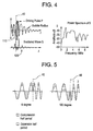
- f h may be around 2 f l and echoes may be filtered around 2 f l upon reception.
- two continuous expansion periods 110 may be employed at the switch time 40 as shown in Fig. 4.
- the bubble acts more like a linear mass-spring system since the radial displacement does not cause large surface pressure changes (see Fig. 1 and Equation 1). Therefore, more energy around the driving frequency (i.e. 2 f l ) is scattered. Also, since the scatter cross-section is proportional to the square of the bubble size, a higher amplitude scattered wave may be expected than using the 2 f l frequency wave to drive a static bubble.
- the nonlinear response of the bubble is also strengthened since the second compression period of the high frequency wave component is in phase with bubble compression and results in more compression displacement and higher bubble wall velocity. Therefore, a stronger scattered wave 120 is achieved shortly after that half period as shown in Fig. 4.
- the total bubble response around 2 f l will be the combination of the enhanced nonlinear response and linear response around 2 f l .
- a higher CTR may be achieved because of the enhanced nonlinear response and also, since even at linear phase, bubbles still give stronger scattering than tissue because the bubbles have much larger compressibility than tissue.
- a higher SNR may also be achieved since the amplitude of the scattered wave 120 is much stronger than just transmitting a low frequency wave centered at f l which has the same length as the stepped-chirp waveform.
- a natural application of the nonlinear relation between bubble surface pressure and the bubble radius displacement is to enhance pulse inversion imaging using a pair of phase-inverted stepped-chirp waveforms.
- the stepped-chirp waveform in Fig. 2 is defined as the 0 degree pulse and the phase-inverted version of the 0 degree pulse is defined as the 180 degree pulse as shown in Fig. 5, then it is clear that the 180 degree pulse gives a longer time of expansion around the switch time 40 as shown in Fig. 5.
- a radius displacement in the expansion direction 20 causes almost no change in bubble surface pressure compared to the same amount of displacement in the bubble compression phase 10.
- the scattered wave from the bubble in 180 degree pulse transmission is not enhanced as much as in 0 degree pulse transmission.
- tissue because of the much weaker nonlinearity compared to bubbles, no significant difference may be found between the echoes from the 0 degree transmission and the 180 degree transmission.
- CTR and SNR may be enhanced in receiving after coherent summation of the echo signals from the ultrasonic contrast agent and the tissue in the two phase-inverted stepped-chirp transmissions.
- strong enhancement may be achieved around 2 f l compared to just using a pair of phase-inverted low frequency components of the stepped-chirp as in regular phase-inversion imaging.
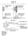
- the received echoes from the first and the second firings may be filtered around 2 f l before or after coherent summation to get strong CTR.
- Fig. 6 shows simulated results of the scattered wave 130 (after coherent summation) and power spectrum with 2MHz regular phase-inversion imaging and with 2MHz and 4Mhz stepped-chirp imaging. About 7 to 8 dB enhancement is achieved around 4MHz using a pair of phase-inverted stepped-chirp waveforms.
- the stepped-chirp waveform may also be used in multiple-firing (including single firing and double firings) situations with phase or amplitude coded transmission waves.
- the two pulses may not need to be totally phase inverted, e.g. there may be one part 140 of the second waveform inverted, while another part 150 is not inverted, as shown in Fig 7 (a pair of stepped-chirp waveforms that are not totally phase-inverted...first part 90 degree phase shifted, second part inverted).
- Fig 7 a pair of stepped-chirp waveforms that are not totally phase-inverted...first part 90 degree phase shifted, second part inverted.
- Each stepped-chirp waveform may be a combination of two or more discrete frequency components. The combination may be one component simply following the other component or one component adding to another component on top of itself or on part of itself.
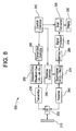
- Fig. 8 illustrates a block diagram of an ultrasonic diagnostic imaging system 200 constructed in accordance with an embodiment of the present invention.
- the system includes a transducer array 210 that is coupled via a transmit/receive switch 220 with a transmitter 230 and receiver 240.
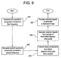
- the stepped-chirp waveform generator 250 For a single pulse K, referring to Fig. 8 and Fig. 9, in steps 410 and 420, the stepped-chirp waveform generator 250 generates a single stepped-chirp pulse with a first waveform component centered at a first center frequency and at least a second waveform component centered at least at a second frequency.
- the single stepped-chirp pulse there are at least two ways to generate the single stepped-chirp pulse: 1. design the stepped-chirp pulse offline then generate the whole single stepped-chirp pulse K and save it in the transmit memory for transmitting. 2. generate the first waveform component at a first frequency, then generate at least a second waveform component at least at a second frequency separately, and then combine the at least two waveform components as a single stepped-chirp pulse K.
- step 430 the generated single stepped-chirp pulse K is transmitted into a subject by transmitter 230 through transducer array 210.
- receiver 240 and beamformer 270 generate received signals from the echoes of the reflected stepped-chirp pulse and store the received signals in memory 280.
- a compression filter is not used upon reception.
- step 450 the received signals are processed to generate a displayed contrast image.
- the bandwidth and center frequency of the receive bandpass filter of the receiver 240 may be adjusted to obtain the best contrast response.
- the center frequency may be one of the transmit frequencies (each waveform component has its own transmit frequency), or one of the subharmonic, ultraharmonic, second harmonic or higher order harmonics of one of the transmit frequencies.
- the receive bandwidth may be broad enough to include one or more than one of the frequency bands described above.
- a stepped-chirp pulse K+1 (K ⁇ [1, N-1]) is transmitted after echoes from transmitted stepped-chirp pulse K is received as illustrated in Fig. 10.
- the echoes from each firing are received sequentially by receiver 240 as shown in Fig. 10.
- the received signals [R1 - RN] are each beamformed and filtered by beamformer 270 and stored in memory 280, controlled by receiver controller 290.
- step 450 after the N number of received signals are acquired, they are integrated together by signal processor 310 (including coherent summation). Then the resultant processed signals are sent to the scan converter 320 and finally displayed on the monitor of display 330.
- the central controller 340 coordinates all higher-level functions of the ultrasound imaging system.
- received echoes reflected from all or some of the transmitted stepped-chirp pulses may be coherently summed before beamforming and filtering.
- a stepped-chirp pulse having more than two waveform components may be generated and transmitted.
- a stepped-chirp pulse may have three waveform components each at a different center frequency.
- CTR and SNR may be enhanced during ultrasound contrast imaging using stepped-chirp waveforms.
- the stepped-chirp waveforms are designed to exploit the nonlinear properties of the contrast bubbles and not for fundamental or harmonic tissue imaging.
- the stepped-chirp waveforms are composed of at least two components centered at different frequencies and cannot be derived by convolving any single pulse with a known coding function.
- a compression filter is not used in the reception process.
- the receiving frequency band may mostly overlap the transmitting frequency band (i.e. there may not be a distinct separation of the receiver frequency band and the transmitting frequency band).
Landscapes
- Physics & Mathematics (AREA)
- Engineering & Computer Science (AREA)
- Radar, Positioning & Navigation (AREA)
- Remote Sensing (AREA)
- Acoustics & Sound (AREA)
- Computer Networks & Wireless Communication (AREA)
- General Physics & Mathematics (AREA)
- Health & Medical Sciences (AREA)
- Life Sciences & Earth Sciences (AREA)
- Nonlinear Science (AREA)
- Radiology & Medical Imaging (AREA)
- Surgery (AREA)
- Nuclear Medicine, Radiotherapy & Molecular Imaging (AREA)
- Biomedical Technology (AREA)
- Heart & Thoracic Surgery (AREA)
- Medical Informatics (AREA)
- Molecular Biology (AREA)
- Pathology (AREA)
- Animal Behavior & Ethology (AREA)
- General Health & Medical Sciences (AREA)
- Public Health (AREA)
- Veterinary Medicine (AREA)
- Biophysics (AREA)
- Ultra Sonic Daignosis Equipment (AREA)
Applications Claiming Priority (2)
| Application Number | Priority Date | Filing Date | Title |
|---|---|---|---|
| US65180 | 2002-09-24 | ||
| US10/065,180 US6953434B2 (en) | 2002-09-24 | 2002-09-24 | Method and apparatus to enhance ultrasound contrast imaging using stepped-chirp waveforms |
Publications (2)
| Publication Number | Publication Date |
|---|---|
| EP1406096A1 true EP1406096A1 (fr) | 2004-04-07 |
| EP1406096B1 EP1406096B1 (fr) | 2009-03-11 |
Family
ID=31989999
Family Applications (1)
| Application Number | Title | Priority Date | Filing Date |
|---|---|---|---|
| EP03255973A Expired - Lifetime EP1406096B1 (fr) | 2002-09-24 | 2003-09-23 | Procédé et appareil pour améliorer l'imagerie ultrasonore par agent de contrast en utilisant une modulation de fréquence en créneaux |
Country Status (5)
| Country | Link |
|---|---|
| US (1) | US6953434B2 (fr) |
| EP (1) | EP1406096B1 (fr) |
| JP (1) | JP4667733B2 (fr) |
| CN (1) | CN100409812C (fr) |
| DE (1) | DE60326527D1 (fr) |
Cited By (4)
| Publication number | Priority date | Publication date | Assignee | Title |
|---|---|---|---|---|
| EP1774361A2 (fr) * | 2004-06-18 | 2007-04-18 | ANGELSEN, Bjorn A. J. | Detection du`n agent de contraste par ultrasons et imagerie par manipulation avec des frequences basses des characteristiques de diffusion de frquences hautes |
| EP1965224A3 (fr) * | 2007-02-27 | 2008-10-15 | Hitachi, Ltd. | Appareil de formation d'images à ultrasons |
| EP2154548A1 (fr) | 2008-08-08 | 2010-02-17 | Aloka Co., Ltd. | Appareil de diagnostic à ultrasons pour échographie nonlinéaire |
| US10468009B2 (en) | 2012-12-19 | 2019-11-05 | The University Of Leeds | Ultrasound generation |
Families Citing this family (29)
| Publication number | Priority date | Publication date | Assignee | Title |
|---|---|---|---|---|
| US6685645B1 (en) | 2001-10-20 | 2004-02-03 | Zonare Medical Systems, Inc. | Broad-beam imaging |
| US6866631B2 (en) * | 2001-05-31 | 2005-03-15 | Zonare Medical Systems, Inc. | System for phase inversion ultrasonic imaging |
| US20040230121A1 (en) * | 2003-02-20 | 2004-11-18 | Rune Hansen | Ultrasonic contrast agent imaging by dualband pulse transmission |
| JP4557573B2 (ja) * | 2003-03-14 | 2010-10-06 | 株式会社東芝 | 超音波診断装置及び超音波診断装置の作動方法 |
| EP1515158B1 (fr) * | 2003-09-09 | 2013-07-17 | Esaote S.p.A. | Méthode d'imagerie à ultrasons en combinaison avec la presence d'un agent de contraste dans un objet à examiner |
| JP4499477B2 (ja) * | 2004-05-26 | 2010-07-07 | アロカ株式会社 | 超音波診断装置 |
| US20050273010A1 (en) * | 2004-06-02 | 2005-12-08 | Shi William T | Method and system for ultrasound contrast-imaging |
| WO2006058006A2 (fr) * | 2004-11-22 | 2006-06-01 | Baker Hughes Incorporated | Identification de reponse de frequence de canal a l'aide de signaux chirp et de frequences en palier |
| JP4627675B2 (ja) * | 2005-03-29 | 2011-02-09 | アロカ株式会社 | 超音波診断装置 |
| US8233554B2 (en) | 2010-03-29 | 2012-07-31 | Eices Research, Inc. | Increased capacity communications for OFDM-based wireless communications systems/methods/devices |
| US8670493B2 (en) * | 2005-06-22 | 2014-03-11 | Eices Research, Inc. | Systems and/or methods of increased privacy wireless communications |
| USRE47633E1 (en) | 2005-06-22 | 2019-10-01 | Odyssey Wireless Inc. | Systems/methods of conducting a financial transaction using a smartphone |
| EP1739455A1 (fr) * | 2005-06-23 | 2007-01-03 | I.N.S.E.R.M. Institut National de la Sante et de la Recherche Medicale | Imagerie ultrasonore d'agents de contrast utilisant des rampes de fréquences inversées |
| WO2008036567A2 (fr) * | 2006-09-18 | 2008-03-27 | The Trustees Of Dartmouth College | Système et procédé de visualisation d'objets à travers des milieux troubles |
| US8100832B2 (en) * | 2007-04-27 | 2012-01-24 | Hitachi Aloka Medical, Ltd. | Ultrasound diagnostic apparatus |
| JP5294295B2 (ja) * | 2007-12-07 | 2013-09-18 | ジーイー・メディカル・システムズ・グローバル・テクノロジー・カンパニー・エルエルシー | 超音波診断装置及び超音波診断治療システム |
| JP5629052B2 (ja) * | 2008-06-03 | 2014-11-19 | 日立アロカメディカル株式会社 | 超音波診断装置 |
| JP5654198B2 (ja) * | 2008-06-16 | 2015-01-14 | 日立アロカメディカル株式会社 | 超音波診断装置 |
| US9374746B1 (en) | 2008-07-07 | 2016-06-21 | Odyssey Wireless, Inc. | Systems/methods of spatial multiplexing |
| CN102088320B (zh) * | 2009-12-03 | 2013-10-30 | 建兴电子科技股份有限公司 | 超音波系统及其通讯方法 |
| GB2498519A (en) * | 2012-01-11 | 2013-07-24 | Univ Erasmus Medical Ct | Ultrasound imaging |
| CN103549975B (zh) * | 2013-10-14 | 2016-08-10 | 华南理工大学 | 基于跳频超声信号分离的结石检测装置及其方法 |
| CN103845080A (zh) * | 2014-02-25 | 2014-06-11 | 深圳京柏医疗设备有限公司 | 一种基于线性调频编码的超声脐带血流测量系统及方法 |
| US10527592B2 (en) * | 2015-09-16 | 2020-01-07 | Samsung Medison Co., Ltd. | Ultrasonic probe, ultrasonic imaging apparatus including the same, and method for controlling the ultrasonic imaging apparatus |
| US10751028B2 (en) | 2016-04-01 | 2020-08-25 | The Board Of Trustees Of The Leland Stanford Junior University | Coherence-based beamforming for improved microbubble detection in contrast enhanced ultrasound |
| CN108957412A (zh) * | 2018-07-12 | 2018-12-07 | 西安电子科技大学 | 基于分段式线性调频信号的雷达探测与通信传输方法 |
| US11684807B2 (en) * | 2018-12-27 | 2023-06-27 | Insightec Ltd. | Optimization of transducer configurations in ultrasound procedures |
| CN111803126B (zh) | 2019-04-11 | 2025-04-01 | 深圳迈瑞生物医疗电子股份有限公司 | 执行诊断超声成像的方法和系统 |
| CN111358435B (zh) * | 2020-03-13 | 2023-02-28 | 珠海向量科技有限公司 | 一种提高深度神经网络精度的数据增强方法 |
Citations (3)
| Publication number | Priority date | Publication date | Assignee | Title |
|---|---|---|---|---|
| US5833615A (en) * | 1997-05-09 | 1998-11-10 | Thomas Jefferson University | Excitation enhanced ultrasound system |
| US5966169A (en) * | 1997-03-15 | 1999-10-12 | Bullis; James K. | Three dimensional beamformed television |
| US6401539B1 (en) * | 1997-08-01 | 2002-06-11 | Acuson Corporation | Ultrasonic imaging aberration correction system and method |
Family Cites Families (12)
| Publication number | Priority date | Publication date | Assignee | Title |
|---|---|---|---|---|
| US5410516A (en) * | 1988-09-01 | 1995-04-25 | Schering Aktiengesellschaft | Ultrasonic processes and circuits for performing them |
| US5540909A (en) * | 1994-09-28 | 1996-07-30 | Alliance Pharmaceutical Corp. | Harmonic ultrasound imaging with microbubbles |
| US5678553A (en) * | 1994-11-01 | 1997-10-21 | Schering Aktiengesellschaft | Ultrasonic processes and circuits for carrying out those processes |
| US5724976A (en) * | 1994-12-28 | 1998-03-10 | Kabushiki Kaisha Toshiba | Ultrasound imaging preferable to ultrasound contrast echography |
| US5706819A (en) * | 1995-10-10 | 1998-01-13 | Advanced Technology Laboratories, Inc. | Ultrasonic diagnostic imaging with harmonic contrast agents |
| US5632277A (en) * | 1996-06-28 | 1997-05-27 | Siemens Medical Systems, Inc. | Ultrasound imaging system employing phase inversion subtraction to enhance the image |
| US6193663B1 (en) * | 1997-12-18 | 2001-02-27 | Acuson Corporation | Diagnostic ultrasound imaging method and system with improved frame rate |
| US6213947B1 (en) * | 1999-03-31 | 2001-04-10 | Acuson Corporation | Medical diagnostic ultrasonic imaging system using coded transmit pulses |
| US6117082A (en) * | 1999-03-31 | 2000-09-12 | Acuson Corporation | Medical diagnostic ultrasound imaging system and method with fractional harmonic seed signal |
| US6371914B1 (en) * | 2000-04-13 | 2002-04-16 | Bracco Research S.A. | Single-shot phase cancellation ultrasound contrast imaging |
| JP4232134B2 (ja) * | 2001-02-01 | 2009-03-04 | 株式会社日立メディコ | 超音波造影描画装置 |
| US6440074B1 (en) * | 2001-08-06 | 2002-08-27 | Koninklijke Philips Electronics N. V. | Ultrasonic diagnostic imaging with nonlinearly intermodulated frequency components |
-
2002
- 2002-09-24 US US10/065,180 patent/US6953434B2/en not_active Expired - Lifetime
-
2003
- 2003-09-22 JP JP2003329247A patent/JP4667733B2/ja not_active Expired - Fee Related
- 2003-09-23 EP EP03255973A patent/EP1406096B1/fr not_active Expired - Lifetime
- 2003-09-23 DE DE60326527T patent/DE60326527D1/de not_active Expired - Lifetime
- 2003-09-24 CN CNB031587704A patent/CN100409812C/zh not_active Expired - Fee Related
Patent Citations (3)
| Publication number | Priority date | Publication date | Assignee | Title |
|---|---|---|---|---|
| US5966169A (en) * | 1997-03-15 | 1999-10-12 | Bullis; James K. | Three dimensional beamformed television |
| US5833615A (en) * | 1997-05-09 | 1998-11-10 | Thomas Jefferson University | Excitation enhanced ultrasound system |
| US6401539B1 (en) * | 1997-08-01 | 2002-06-11 | Acuson Corporation | Ultrasonic imaging aberration correction system and method |
Cited By (6)
| Publication number | Priority date | Publication date | Assignee | Title |
|---|---|---|---|---|
| EP1774361A2 (fr) * | 2004-06-18 | 2007-04-18 | ANGELSEN, Bjorn A. J. | Detection du`n agent de contraste par ultrasons et imagerie par manipulation avec des frequences basses des characteristiques de diffusion de frquences hautes |
| EP1965224A3 (fr) * | 2007-02-27 | 2008-10-15 | Hitachi, Ltd. | Appareil de formation d'images à ultrasons |
| CN101254119B (zh) * | 2007-02-27 | 2010-06-02 | 株式会社日立制作所 | 超声波摄像装置 |
| EP2154548A1 (fr) | 2008-08-08 | 2010-02-17 | Aloka Co., Ltd. | Appareil de diagnostic à ultrasons pour échographie nonlinéaire |
| US8740799B2 (en) | 2008-08-08 | 2014-06-03 | Hitachi Aloka Medical, Ltd. | Ultrasound diagnostic apparatus |
| US10468009B2 (en) | 2012-12-19 | 2019-11-05 | The University Of Leeds | Ultrasound generation |
Also Published As
| Publication number | Publication date |
|---|---|
| US20040059225A1 (en) | 2004-03-25 |
| DE60326527D1 (de) | 2009-04-23 |
| EP1406096B1 (fr) | 2009-03-11 |
| CN1494874A (zh) | 2004-05-12 |
| US6953434B2 (en) | 2005-10-11 |
| JP2004113788A (ja) | 2004-04-15 |
| CN100409812C (zh) | 2008-08-13 |
| JP4667733B2 (ja) | 2011-04-13 |
Similar Documents
| Publication | Publication Date | Title |
|---|---|---|
| EP1406096B1 (fr) | Procédé et appareil pour améliorer l'imagerie ultrasonore par agent de contrast en utilisant une modulation de fréquence en créneaux | |
| US6440075B1 (en) | Ultrasonic diagnostic imaging of nonlinearly intermodulated and harmonic frequency components | |
| Chang et al. | Second harmonic imaging and harmonic Doppler measurements with Albunex | |
| Borsboom et al. | Nonlinear coded excitation method for ultrasound contrast imaging | |
| Bouakaz et al. | Super harmonic imaging: a new imaging technique for improved contrast detection | |
| JP5275798B2 (ja) | 超音波撮像方法 | |
| EP2154548B1 (fr) | Appareil de diagnostic à ultrasons pour échographie nonlinéaire | |
| CA2659645C (fr) | Sequences d'inversion d'impulsion pour imagerie non lineaire | |
| US6494839B1 (en) | Ultrasonic diagnostic imaging system transmitter for sum and difference frequency imaging | |
| US6783496B2 (en) | Method and apparatus for improving contrast-to-tissue ratio in ultrasound contrast imaging with subharmonic imaging | |
| Hu et al. | Coded excitation using biphase-coded pulse with mismatched filters for high-frequency ultrasound imaging | |
| Bouakaz et al. | Improved contrast to tissue ratio at higher harmonics | |
| Wyczalkowski et al. | Optimization of acoustic scattering from dual-frequency driven microbubbles at the difference frequency | |
| Novell et al. | Contrast agent response to chirp reversal: simulations, optical observations, and acoustical verification | |
| US6440074B1 (en) | Ultrasonic diagnostic imaging with nonlinearly intermodulated frequency components | |
| de Jong et al. | Harmonic imaging for ultrasound contrast agents | |
| US20080275345A1 (en) | Ultrasonic Diagnostic Contrast Imaging at Moderate Mi Levels | |
| WO2009072022A1 (fr) | Imagerie de contraste à ultrason avec amélioration d'oscillation micro-bulle | |
| Chetty et al. | Investigating the nonlinear microbubble response to chirp encoded, multipulse sequences | |
| US20240337737A1 (en) | System and methods for transmission of non-diffracting acoustic beams | |
| Cheng et al. | Dual-frequency chirp imaging for contrast detection | |
| de Jong et al. | 2C-4 Chirp Reversal Ultrasound Contrast Imaging | |
| Yen et al. | P3J-2 Mismatched-Filter Design for Biphase-Coded Pulse for High Frequency Ultrasound Imaging | |
| Borsboom et al. | Nonlinear coded excitation method for contrast imaging | |
| Waters et al. | Sensing a buried resonant object by single-channel time reversal |
Legal Events
| Date | Code | Title | Description |
|---|---|---|---|
| PUAI | Public reference made under article 153(3) epc to a published international application that has entered the european phase |
Free format text: ORIGINAL CODE: 0009012 |
|
| AK | Designated contracting states |
Kind code of ref document: A1 Designated state(s): AT BE BG CH CY CZ DE DK EE ES FI FR GB GR HU IE IT LI LU MC NL PT RO SE SI SK TR |
|
| AX | Request for extension of the european patent |
Extension state: AL LT LV MK |
|
| RIN1 | Information on inventor provided before grant (corrected) |
Inventor name: PANDA, SATCHI Inventor name: MILLER, STEVEN C. Inventor name: HAO, XIAOHUI Inventor name: CHIAO, RICHARD Y. |
|
| 17P | Request for examination filed |
Effective date: 20041007 |
|
| AKX | Designation fees paid |
Designated state(s): DE FR NL |
|
| 17Q | First examination report despatched |
Effective date: 20080130 |
|
| GRAP | Despatch of communication of intention to grant a patent |
Free format text: ORIGINAL CODE: EPIDOSNIGR1 |
|
| GRAS | Grant fee paid |
Free format text: ORIGINAL CODE: EPIDOSNIGR3 |
|
| GRAA | (expected) grant |
Free format text: ORIGINAL CODE: 0009210 |
|
| AK | Designated contracting states |
Kind code of ref document: B1 Designated state(s): DE FR NL |
|
| REF | Corresponds to: |
Ref document number: 60326527 Country of ref document: DE Date of ref document: 20090423 Kind code of ref document: P |
|
| PG25 | Lapsed in a contracting state [announced via postgrant information from national office to epo] |
Ref country code: NL Free format text: LAPSE BECAUSE OF FAILURE TO SUBMIT A TRANSLATION OF THE DESCRIPTION OR TO PAY THE FEE WITHIN THE PRESCRIBED TIME-LIMIT Effective date: 20090311 |
|
| NLV1 | Nl: lapsed or annulled due to failure to fulfill the requirements of art. 29p and 29m of the patents act | ||
| PLBE | No opposition filed within time limit |
Free format text: ORIGINAL CODE: 0009261 |
|
| STAA | Information on the status of an ep patent application or granted ep patent |
Free format text: STATUS: NO OPPOSITION FILED WITHIN TIME LIMIT |
|
| 26N | No opposition filed |
Effective date: 20091214 |
|
| REG | Reference to a national code |
Ref country code: FR Ref legal event code: ST Effective date: 20100531 |
|
| PG25 | Lapsed in a contracting state [announced via postgrant information from national office to epo] |
Ref country code: FR Free format text: LAPSE BECAUSE OF NON-PAYMENT OF DUE FEES Effective date: 20090930 |
|
| PGFP | Annual fee paid to national office [announced via postgrant information from national office to epo] |
Ref country code: DE Payment date: 20130927 Year of fee payment: 11 |
|
| REG | Reference to a national code |
Ref country code: DE Ref legal event code: R119 Ref document number: 60326527 Country of ref document: DE |
|
| PG25 | Lapsed in a contracting state [announced via postgrant information from national office to epo] |
Ref country code: DE Free format text: LAPSE BECAUSE OF NON-PAYMENT OF DUE FEES Effective date: 20150401 |