EP1406149A2 - Kapazitive Detektion - Google Patents
Kapazitive Detektion Download PDFInfo
- Publication number
- EP1406149A2 EP1406149A2 EP03012061A EP03012061A EP1406149A2 EP 1406149 A2 EP1406149 A2 EP 1406149A2 EP 03012061 A EP03012061 A EP 03012061A EP 03012061 A EP03012061 A EP 03012061A EP 1406149 A2 EP1406149 A2 EP 1406149A2
- Authority
- EP
- European Patent Office
- Prior art keywords
- capacitor
- terminal
- bucket
- charge
- scoop
- Prior art date
- Legal status (The legal status is an assumption and is not a legal conclusion. Google has not performed a legal analysis and makes no representation as to the accuracy of the status listed.)
- Withdrawn
Links
Images


Classifications
-
- G—PHYSICS
- G06—COMPUTING OR CALCULATING; COUNTING
- G06F—ELECTRIC DIGITAL DATA PROCESSING
- G06F3/00—Input arrangements for transferring data to be processed into a form capable of being handled by the computer; Output arrangements for transferring data from processing unit to output unit, e.g. interface arrangements
- G06F3/01—Input arrangements or combined input and output arrangements for interaction between user and computer
- G06F3/03—Arrangements for converting the position or the displacement of a member into a coded form
- G06F3/033—Pointing devices displaced or positioned by the user, e.g. mice, trackballs, pens or joysticks; Accessories therefor
- G06F3/0354—Pointing devices displaced or positioned by the user, e.g. mice, trackballs, pens or joysticks; Accessories therefor with detection of two-dimensional [2D] relative movements between the device, or an operating part thereof, and a plane or surface, e.g. 2D mice, trackballs, pens or pucks
- G06F3/03543—Mice or pucks
-
- G—PHYSICS
- G06—COMPUTING OR CALCULATING; COUNTING
- G06F—ELECTRIC DIGITAL DATA PROCESSING
- G06F1/00—Details not covered by groups G06F3/00 - G06F13/00 and G06F21/00
- G06F1/26—Power supply means, e.g. regulation thereof
- G06F1/32—Means for saving power
- G06F1/3203—Power management, i.e. event-based initiation of a power-saving mode
-
- G—PHYSICS
- G06—COMPUTING OR CALCULATING; COUNTING
- G06F—ELECTRIC DIGITAL DATA PROCESSING
- G06F1/00—Details not covered by groups G06F3/00 - G06F13/00 and G06F21/00
- G06F1/26—Power supply means, e.g. regulation thereof
- G06F1/32—Means for saving power
- G06F1/3203—Power management, i.e. event-based initiation of a power-saving mode
- G06F1/3206—Monitoring of events, devices or parameters that trigger a change in power modality
- G06F1/3231—Monitoring the presence, absence or movement of users
-
- Y—GENERAL TAGGING OF NEW TECHNOLOGICAL DEVELOPMENTS; GENERAL TAGGING OF CROSS-SECTIONAL TECHNOLOGIES SPANNING OVER SEVERAL SECTIONS OF THE IPC; TECHNICAL SUBJECTS COVERED BY FORMER USPC CROSS-REFERENCE ART COLLECTIONS [XRACs] AND DIGESTS
- Y02—TECHNOLOGIES OR APPLICATIONS FOR MITIGATION OR ADAPTATION AGAINST CLIMATE CHANGE
- Y02D—CLIMATE CHANGE MITIGATION TECHNOLOGIES IN INFORMATION AND COMMUNICATION TECHNOLOGIES [ICT], I.E. INFORMATION AND COMMUNICATION TECHNOLOGIES AIMING AT THE REDUCTION OF THEIR OWN ENERGY USE
- Y02D10/00—Energy efficient computing, e.g. low power processors, power management or thermal management
Definitions
- the present invention relates to sensing systems and methods that may be advantageously used in managing power consumption in electronic devices, particularly hand operated data input devices, and for other purposes. More specifically, the invention relates to sensing systems and methods that may be used to conserve battery power in wireless data input devices having components that consume power at a relatively high rate.
- Power management in electronic devices is becoming increasingly important as greater reliance is placed on battery power, e.g., for portable computers, personal data assistants (PDAs), tablet computers, cellular phones, pagers, and wireless computer peripherals.
- PDAs personal data assistants
- the components of such devices are becoming increasingly power hungry, and the demand for longer intervals between battery replacement or recharging has increased.
- Such devices are often turned on for ready usability but left idle for significant periods of time. This presents an opportunity to reduce depletion of battery power through the use of reduced power modes.
- cursor control (pointing) devices such as a computer mouse and trackball device have been made wireless by inclusion of a battery power source within the device and the provision of a wireless data link, e.g., an infrared or RF transmitter/receiver pair.
- a wireless data link e.g., an infrared or RF transmitter/receiver pair.
- optical tracking can provide more reliable and accurate tracking by eliminating moving parts (e.g., a ball and associated encoder wheels), which are prone to malfunction from the pick-up of dirt, oils, etc. from the tracked support surface and/or a user's hand.
- optical tracking requires considerably more power for driving the circuitry used to illuminate a trackable surface and to receive and process light (image information) reflected from the trackable surface.
- Exemplary optical tracking systems, and associated signal processing techniques are disclosed in commonly owned U.S. Patent No. 6,172,354 (Adan et al.) and copending applications Serial No. 09/692,120, filed October 19, 2000, and Serial No. 09/273,899, filed March 22, 1999, each of which is hereby incorporated by reference in its entirety.
- Tournai U.S. Patent No. 5,408,668 describes a processor based control system for connecting and disconnecting a computer peripheral device (e.g., a display monitor or printer) to a power source.
- the control is based upon input activity signals received from an input source such as a keyboard, mouse, printer or an occupancy sensor.
- Mese et al. U.S. Patent No. 5,396,443 describes power saving control arrangements for information processing apparatus. More specifically, the Mese et al. '443 patent describes various systems for (1) detecting the approach (or contact) of a user associated medium to (or with) the apparatus; (2) placing a controlled object of the apparatus in a non-power saving state when such contact or approach is detected; and (3) placing the controlled object in a power saving state when the presence of the user associated medium (i.e., a stylus pen or part of a user's body) is not detected for a predetermined period of time.
- the user associated medium i.e., a stylus pen or part of a user's body
- a contact or approach detecting tablet, and a flat display panel may be integrally formed with a housing of the information processing apparatus.
- a voltage-limited current source feeds a charging current to a plate.
- a discharge switch controlled by a microprocessor closes briefly to discharge the sensing plate into a charge detector, e.g., a charge detecting capacitor.
- the amount of charge so transferred is representative of the capacitance of the sensing plate.
- the charge-discharge process can be repeated numerous times, in which case the charge measurement means aggregates the charge from the plate over several operating cycles.
- the charge detector is examined for total final charge, by an A/D converter, and as a result the controller may generate an output control signal on an output line, which may be used to cause a faucet to open.
- the controller After each reading, the controller resets the charge detector to allow it to accumulate a fresh set of charges from the plate.
- the controller can take a reading after each individual cycle of the discharging switch, and then integrate (or otherwise filter) the readings over a number of cycles prior to making a logical decision resulting in a control output.
- a power control circuit for powering down portions of a personal computer in response to user inactivity, and for delivering full power to these portions once user activity is detected via one or more sensors.
- the components to which power is reduced (or removed) are components, which can respond almost immediately to being turned on.
- components which require a period of time to come up to full operation e.g., disk drive motors, monitor, main processor
- the sensor is a piezoelectric sensor fitted into a keyboard.
- sensors may be positioned at other locations on the computer (a monitor, mouse, trackball, touch pad or touch screen) and that various other kinds of sensors (capacity, stress, temperature, light) could be used instead of piezoelectric sensors.
- capacitive proximity sensing is carried out by detecting a relative change in the capacitance of a "scoop" capacitor formed by a conductor and surrounding ground plane.
- the conductor may be a plate provided in the form of an adhesive label printed with conductive ink. Charge is transferred between the scoop capacitor and a relatively large "bucket capacitor,” and a voltage of the bucket capacitor is applied to an input threshold switch.
- a state transition from low to high (or high to low) of the input threshold is detected, and a value indicative of the number of cycles of charge transfer required to reach the state transition is determined.
- the presence or absence of an object or body portion in close proximity to or in contact with a device can be determined by comparing the value with a predetermined threshold.
- the predetermined threshold can be adjusted to take into account environmentally induced changes in capacitance of the scoop capacitor.
- a change in environmental capacitance caused by the proximity of a user's hand is detected so that power can be saved by turning "off' the high current optical (or other type of) tracking system when the mouse/pen is not in use.
- the determination of this condition requires periodic sequences of microprocessor operation, causing increased current draw during the detection interval. This interval remains relatively long, because each time the touch system is operated a count is generated as the "bucket" capacitor is charged from 0 Volts up to the arbitrary threshold determined by the internal comparator.
- the typical mouse user wants no sign of lag or delay in mouse response. Users are generally sensitive to motion down to approximately 0.01 ips and can move a mouse up to approximately 25 ips. Optical tracking affords a level of responsiveness commensurate with user sensitivities.
- capacitive sensing techniques e.g., as described in application Serial No. 09/948,099
- aggressive users e.g., gamers utilizing a mouse or other gaming peripheral (e.g., a gamepad)
- Sampling at a higher rate can alleviate perceived deficiencies in responsiveness, but increased sampling adversely affects battery life.
- the present invention has as an object to reduce the time and energy required to successfully detect the presence of a human hand or other instrumentality in contact or close proximity with a data input device, e.g., a computer mouse, while improving the reliability of the detection.
- the capacitive sensing systems and methods of the invention may be advantageously utilized to provide effective power management in user operated data input devices.
- the invention is not limited to power management, however, and can be implemented in essentially any application (data input devices or otherwise) where there is a desire to reliably and efficiently sense the presence (or absence) of an object or body portion in contact with or close proximity to another object.
- Particularly advantageous use may be made of the inventive capacitive sensing together with power management systems and methods as described in copending commonly owned U.S.
- a wireless cursor control device e.g., computer mouse or trackball device
- other user operated data input device e.g., a wireless gaming peripheral such as a gamepad, or a handheld digitizing pen
- circuit components e.g., an optical tracking system and/or RF transmitter
- the system and method disclosed in U.S. application Serial No. 09/948,099 may be modified such that an arbitrary but repeatable non-zero offset charge level of the bucket capacitor is set at the initiation of a detection sequence.
- Such an offset charge induced into the bucket capacitor allows the count range to be reduced by an amount proportional to the offset charge.
- an offset charge causing the sample period to be reduced by half would allow determination of a hand presence twice as often, doubling responsiveness of the system to operator actuation.
- an offset which reduces the sample period to one fourth would not only allow the responsiveness to improve by 2:1 but also a reduction by one half of the power required to carry out detection in a suspend state of the mouse.
- an offset charge and interval rate may be chosen to optimize both of these parameters.
- a resistor may be wired to an unused or multifunction port pin of a control microprocessor, which allows the microprocessor to inject current into the bucket capacitor prior to the sampling interval.
- Charge injection is a function of the applied voltage duration (time), the resistor value, and the bucket capacitor value.
- the precharge is made repeatable and falls below a range of normal operation for the sample interval. Each sample interval then would accumulate to, e.g., 20 or 30 counts, instead of 100-110 counts.
- the invention is embodied in a capacitive sensing system for sensing the presence of an object or body portion in contact with or close proximity to another object.
- a first conductor is capacitively coupled to a ground to thereby form a scoop capacitor having a capacitance which varies in relation to the proximity of the object or body portion to the conductor.
- a pair of second and third conductors form a bucket capacitor having a capacitance which is larger than a maximum capacitance of the scoop capacitor, and an input threshold switch is provided.
- Charge setting means are provided for setting a charge of the bucket capacitor at a repeatable non-zero reference level.
- Switching means are provided for selectively: connecting at least one of the scoop capacitor and bucket capacitor to a voltage source to charge the at least one capacitor, connecting the charge setting means to the bucket capacitor to set the charge of the bucket capacitor to the repeatable non-zero reference level, varying the charge of the bucket capacitor from the reference level set by the charge setting means, in relation to a relative size of the scoop capacitor, and applying a voltage of the bucket capacitor to the input threshold switch.
- a detector means is provided for detecting an input state of the input threshold switch. Determining means determine a value (TouchVal) relating to a number of cycles of varying of the bucket capacitor charge corresponding to a detection of a transition of the input threshold switch by the detector means.
- Signal generating means generate, based upon TouchVal, a signal indicative of an ON state wherein the object or body portion is in contact with or close proximity to another object, and an OFF state wherein the object or body portion is not in contact with or close proximity to another object.
- the invention is embodied in a method for sensing the presence of an object or body portion in contact with or close proximity to another object.
- the method is carried out with a first conductor capacitively coupled to a ground to thereby form a scoop capacitor having a capacitance which varies in relation to the proximity of the object or body portion to the conductor.
- a pair of second and third conductors are provided, which form a bucket capacitor having a capacitance which is larger than a maximum capacitance of the scoop capacitor; an input threshold switch is also provided.
- Switching is performed to selectively: connect at least one of the scoop capacitor and the bucket capacitor to a voltage source to charge the at least one capacitor, set a charge of the bucket capacitor at a repeatable non-zero reference level, vary the charge of the bucket capacitor from the reference level, in relation to a relative size of the scoop capacitor, and apply a voltage of the bucket capacitor to the input threshold switch.
- An input state of the input threshold switch is detected.
- a value (TouchVal) is determined, which relates to a number of cycles of varying the bucket capacitor charge corresponding to a detection of a transition of the input threshold switch.
- TouchVal Based upon TouchVal, a signal is generated which is indicative of an ON state wherein the object or body portion is in contact with or close proximity to another object, and an OFF state wherein the object or body portion is not in contact with or close proximity to the object.
- the present inventive systems and methods are described herein in terms of an exemplary application thereof within a computer input device, particularly a wireless, optically tracking computer mouse. It will be understood, however, that the inventions have much wider-ranging potential application.
- the capacitive sensing of the present invention is not limited to power management, but rather can be implemented in virtually any device (data input device or otherwise) where it is desired to determine the presence or non-presence of an object or body portion in contact with or close proximity to another object. This includes many applications where various other types of proximity sensors have been used, e.g., water valve actuation in toilets, faucets and drinking fountains, automatic door control systems, alarm systems, security lock systems and safety interlock systems (e.g., for industrial equipment), etc.
- the phrase "contact with or close proximity to another object” as used herein encompasses contact or close proximity with a localized object portion as well as an object in toto, and the use of multiple sensors in conjunction with each other.
- the inventive capacitive sensing system and method may be implemented with plural sensors for position determination purposes and/or for carrying out position dependent data input, interface or other functionalities.
- Such functionalities may include, e.g., touch pad and touch strip functionalities, as well as various computer/user interface functionalities, such as are disclosed, e.g., in co-owned copending application Serial No. 09/804,496, filed March 9, 2001 (and its parent applications).
- the power management aspects of the present invention may find useful application in various types of user operated data input devices - portable and non-portable, wireless and wired, self-contained and peripheral, e.g., to a host computer.
- the invention finds particularly useful application (but is not limited to) battery powered devices which are intermittently used and generally left on over extended periods of time so as to provide ready usability when demand so requires.
- Such devices include (but are not limited to) portable computers, personal data assistants (PDAs), tablet computers, cellular phones, pagers and wireless computer and gaming peripherals, e.g., mice, keyboards, gamepads and handheld digitizing pens.
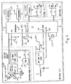
- Fig. 1 shows the circuitry of an exemplary computer mouse that may incorporate a sensing system in accordance with the present invention.
- the mouse is a wireless mouse employing an optical surface tracking system.
- Control logic may be implemented in firmware within a control integrated circuit (IC) 1, e.g., a Sunplus SPMCO2A microprocessor ( ⁇ P), available from Sunplus Technology Company, Ltd. of Hsinchu, Taiwan, or an application specific integrated circuit (ASIC).
- IC control integrated circuit
- ⁇ P Sunplus SPMCO2A microprocessor
- ASIC application specific integrated circuit
- ⁇ P 1 performs signal processing and output functions of the mouse, and controls the wireless transmission of data packets to a host computer via an RF transmitter 5.
- An optical controller 1C 7 forms part of an optical tracking engine, controlling illumination of a LED light source 9 which is used to illuminate a trackable surface (e.g., a desktop).
- IC 7 also processes signals received from an image detector 10 (which may be included as part of IC 7) that receives light reflected from the trackable surface.
- the images are processed by IC 7 using spatial correlation to determine relative displacement values, in pixel or sub-pixel intervals.
- a stream of relative displacement values are communicated by IC 7 to ⁇ P 1 for further processing of the signals into data packets used by the host computer to control the movement of a displayed mouse cursor.
- ⁇ P 1 controls an RF transmission section 5 of the mouse to transmit the data packets to the host computer.
- Fig. 2 is a functional block diagram of a computer 11 used with an exemplary mouse 13 to which the present invention may be applied.
- Mouse 13 illustratively has right and left buttons 15, 17 and a depressible, rotatable scroll wheel 19 located therebetween.
- mouse 13 may have more actuators (such as thumb actuation buttons or more finger actuation buttons), fewer actuators (such as only a single button or two buttons) or different types of actuators (such as triggers, rollers, etc.).
- Mouse 13 may instead be another type of cursor control (pointing) device, such as a trackball device.
- Computer 11 has firmware and/or software providing a mouse driver 21, an operating system 23, a message hook procedure 25, and a focus application 27.
- mouse 13 To initiate a mouse message, the user first manipulates mouse 13. Based on this manipulation, mouse 13 generates a mouse packet that is passed to serial interface 75 and which is indicative of the manipulation event.
- serial interface 75 receives mouse packet, it converts the serial information in the mouse packet into a set of parallel packets and provides the parallel packets to mouse driver 21.
- Mouse driver 21 creates a mouse message based on the manipulation event in a conventional manner.
- Operating system 23 may be a Microsoft "WINDOWS” operating system, e.g., "WINDOWS NT®,” “WINDOWS 95®,” “WINDOWS 98®,” “WINDOWS 2000®”, or “WINDOWS XP®.” Of course, other operating systems can be used as well, such as OS/2 from IBM Corporation, or UNIX, LINUX, or Apple operating systems, as well as myriad embedded application operating systems, such as are available from Wind River, Inc.
- Operating system 23 includes a mouse message hook list that identifies a series of mouse message hook procedures 25. When operating system 23 receives the mouse message from mouse driver 21, it examines the mouse message hook list to determine if any mouse message hook procedures have registered themselves with operating system 23. If at least one mouse message hook procedure has registered itself with operating system 23, operating system 23 passes the mouse message to the registered mouse message hook procedure 25 that appears first on the list.
- the called mouse message hook executes and returns a value to operating system 23 that instructs the operating system to pass the mouse message to the next registered mouse message hook.
- the mouse message may, for example, represent a command to an application which "owns" the window currently under focus in computer 11.
- the message hook procedure 25 issues the command to the focus window application 27.
- the focus window application 27 performs the desired function.
- the message hook procedure 25 consumes the mouse message by removing the message from the message chain. This is accomplished by returning a value to operating system 23 which indicates to the operating system that it should not pass the mouse message to any other message hook procedures.
- Fig. 4 is a more detailed diagram, in partial block form and partial schematic form, illustrating an optical surface tracking mouse 77 to which the present inventive systems may be applied.
- Mouse 77 includes a housing 79, an electromagnetic radiation source (which may be a light source such as an LED) 81, an aperture 83 defined in the bottom of housing 79, a first optical coupler 85, a second optical coupler 87, an image or pattern detector 89, a controller 91, and a current driver 93.
- optical mouse 77 is shown supported relative to a work surface 92.
- Pattern or image detector 89 can be any suitable detector which is capable of detecting images or patterns from information carried by electromagnetic radiation impinging thereon and providing a signal indicative of such patterns or images.
- Pattern detector 89 may be an artificial retina pattern detector, for example, as described in greater detail below.
- light source 81 can be any suitable source of electromagnetic radiation which can be used to provide radiation for impingement on a pattern or image and which can then be detected by pattern detector 89.
- light source 81 includes an LED 95 and an integral lens 97.
- Source 81 could also be a surface mounted LED, or a low grade laser (with a wavelength in the nanometer range), for example.
- optical coupler 85 collects radiation emitted by LED 95 and shapes it. The radiation exits optical coupler 85, passes through housing aperture 83 and impinges upon work surface 92.
- Work surface 92 may be an ordinary planar work surface, e.g., desktop, having no predetermined pattern or texture thereon, or it may be a surface provided with a predetermined pattern, texture or image. The light reflects off of work surface 92 toward optical coupler 87.
- Optical coupler 87 illustratively includes a lens which collects the radiation reflected from surface 92 and directs it to, and focuses it on, image detector (e.g., artificial retina) 89.
- Image detector 89 generates an image signal indicative of an image or pattern on work surface 92, based on the radiation reflected from work surface 92.
- the image signal is provided to controller 91 which computes position information based on the image signal.
- the position information indicates movement of mouse 77 relative to work surface 92, e.g., in a manner such as is described in the above-identified (and incorporated by reference) patents and patent applications.
- Position information is provided by controller 91 in the form of an information packet, which may be transmitted to computer 11 through a cable, or through a wireless transmission link such as an infrared, ultrasonic, or radio frequency (RF) link.
- the position information provided by controller 91 may be provided according to a conventional serial or parallel interface format, such as universal serial bus (USB), FireWireTM, I 2 C, PS2, ECP and EPP interface formats.
- image detector 89 may be an artificial retina.
- a suitable artificial retina manufactured by Mitsubishi Electric Corporation includes a two-dimensional array of variable sensitivity photo detectors (VSPDs) and operates in a known manner.
- the VSPDs are formed by a side-by-side pair of diodes integrated onto and separated by a semi-insulated GaAs layer (pn-np structure).
- the array is a 32x32 element array, but the array could be made larger or smaller as desired.
- the photo detector current depends, both in sign and magnitude, on an applied voltage.
- Such VSPDs exhibit an analog memory effect which stores conductivity information when a voltage is applied in the presence of an optical write pulse. This information is retrieved by injecting an optical readout pulse.
- image detector 89 may be provided as part of an optical tracking IC available from Agilent Technologies Inc. of Palo Alto CA, e.g., the ADNS 2030 and 2050 ICs.
- Associated imaging componentry e.g., LED light source and optical coupling assembly
- Agilent alone or as part of a complete optical tracking engine kit intended for use in the design of an optically tracking mouse.
- Image processing in such devices is based on optical matrix-vector multiplication, or approximations thereof.
- An input image is projected onto the device as a weight matrix.
- All VSPDs have one electrode connected along rows, yielding a sensitivity control vector.
- the VSPD sensitivity can be set to arbitrary values in each row within a certain range.
- the remaining VSPD electrode is connected along columns, yielding an output current vector defined by the matrix vector product of the weight matrix times the sensitivity control vector.
- image detector 89 is controlled, by controller 91, to perform edge extraction operations.
- the sensitivities of two adjacent detector rows are set to +1 and -1, respectively, whereas all other sensitivities are set at 0.
- the output current is proportional to the difference in light intensities of the two active rows.
- mouse 77 also includes a current driver 93 which is coupled to source 81.
- controller 91 can be configured to intermittently sense the intensity of the radiation generated by source 81 and adjust the current provided to source 81 through current driver 93. In other words, if the sensed intensity is lower than a desired range, controller 91 may provide a feedback signal to current driver 93 to boost the current provided to source 81, in order to increase the intensity of the electromagnetic radiation emanating from source 81. If, on the other hand, the intensity of the radiation is higher than a desired range, controller 91 may provide a feedback signal to current driver 93 to reduce the current provided to source 81, to thereby reduce the intensity of the radiation emitted from source 81. This may be done to maximize the signal/noise ratio of the reflected image information. It may also serve as a means, in addition to the present inventive power management systems and methods, for reducing the overall power consumption of mouse 73.
- controller 91 may receive image signals from image detector 89 and process the image signal to generate position information are set out in the co-owned Adan et al. patent and co-pending patent applications mentioned (and incorporated by reference) above. These details are not directly relevant to (and are not necessary to an understanding of) the capacitive sensing system of the present invention. It should be noted, however, that such signal processing consumes considerably more power (typically 20-30 mA) than the signal processing associated with conventional opto-electrical encoder wheel systems (typically 1-2 mA). Additional power is also required for driving the light source of the optical tracking system.
- a mouse to which the present inventive systems may be applied may have a wireless (e.g., RF or infrared) data link to a host computer.
- a wireless (e.g., RF or infrared) data link to a host computer.
- Receiver 101 is an RF receiver that connects to a personal computer 103 with a universal serial bus (USB) cable.
- Mouse 99 incorporates an RF transmitter and may incorporate an optical tracking system as has been described.
- Mouse 99 may be used in an ordinary fashion, e.g., a user can move a cursor across a computer screen by moving the mouse over a flat (planar) surface, and can control the actions of an on-screen cursor in a conventional "point and click" manner.
- mouse 99 When a user moves mouse 99 and clicks its buttons, mouse 99 generates binary data representing this activity, encapsulates the data into packets, and sends the packets to receiver 101 as radio frequency (RF) signals.
- RF radio frequency
- the RF transmission may be carried out in a known manner, the details of which are not necessary to an understanding of the present inventive sensing systems.
- receiver 101 If receiver 101 recognizes mouse 99, it sends the binary data to computer 103. The computer then reacts to the data to cause, for example, the cursor to move across the screen (monitor) 105.
- a power management system in accordance copending U.S. application Serial No. 09/948,099 may be used to power down the mouse when it is not in use.
- a touch/proximity sensor utilizing a novel system and method of capacitive sensing in accordance with the present invention may be employed to provide an indication of usage.
- a relative increase in a capacitance between a conductor and a device ground signals the presence of an object or body portion in contact with or close proximity to another object.
- the system signals the presence or absence of a user's hand or other operation instrumentality (e.g., a pen of pen based data input device) in contact with or close proximity to the device.
- the capacitive sensing system senses the presence of a user's hand on or in close proximity to mouse 99.
- a change in the size of a relatively small capacitor formed between a sensor plate and its surroundings is detected by way of a charge transfer technique, in a manner which avoids processing intensive (and relatively slow) capacitance measurements by an A/D converter or the like.
- a change in the relative size of the small (“scoop") capacitor may be determined by repeatedly dumping the charge of scoop capacitor into a larger (“bucket") capacitor, and counting the number of "scoops” required to "fill” the bucket capacitor.
- the "scoop” capacitor is modulated by the touch or close proximity of a user's hand, for example. The closer the user's hand is to the mouse, the larger the apparent size of the scoop capacitor.
- the present invention builds on the disclosure of U.S. application Serial No. 09/948,099, by providing a system and method for reducing the time and energy it takes to determine a physical count of "scoops" required to "fill” the bucket capacitor.
- the efficiency of the algorithm is improved, and that improvement may be used to extend the battery life of the product in which the algorithm is employed.
- Application Serial No. 09/948,099 describes methods and systems for detecting a change in environmental capacitance caused by the proximity of a human user hand, which allow power to be saved by turning "off' the high current systems, e.g., tracking systems, when the mouse, keyboard, etc., is not in use.
- the determination of this condition involves periodic sequences of microprocessor operation, causing increased current draw during the detection interval. This interval remains relatively long, because each time the touch system is operated a count is generated as the "bucket" capacitor is charged from 0 volts up to an arbitrary threshold determined by an internal comparator.
- a repeatable offset charge is injected into the bucket capacitor at the initiation of the detection sequence. Such an offset allows the count range to be reduced by an amount proportional to the offset charge induced into the bucket capacitor.
- a resistor e.g., 30 kOhm
- impedance 184 could be an inductor used to "flyback" a precharge to the bucket capacitor, or a further capacitor from which a precharge could be transferred.
- an external impedance element could be omitted and the port pin of ⁇ P 1 could be set as a current source for a deterministic time, to precharge the bucket capacitor to a repeatable level.
- the pin is set as a voltage source to charge the bucket capacitor through a resistor
- charge injection is a function of the applied voltage duration (time), the resistor value, and the bucket capacitor value.
- the precharge is made repeatable and, theoretically, may be set at any level producing a voltage below the threshold level of the I/O cell.
- the threshold level of the I/O cell has an uncertainty, due to the fabrication process used to build the silicon, of about +/- 12%.
- clock timing there is generally some variation in clock timing, and the capacitance of the bucket capacitor and scoop capacitor can vary as well, perhaps an additional 10%.
- Each sample (count) set may then accumulate to 20 or 30 counts for example, instead of 100-110 counts.
- the sampling duration is thus reduced to 1 ⁇ 4 of the time duration previously required.
- the difference is 10/20 or 50%. Assuming an interval of 100 mS between sampling cycles and a 5 mS sampling duration, then with a 2 mA gross current (hand-off) draw, the total power draw would be reduced from a 100 uA average to 33 uA.
- the gross power saving which is achievable in this example is 3:1 (hand-off), and this ratio may be altered by the potential to increase the sampling periodicity (frequency) to improve responsiveness. Since the total number of counts may be reduced to the range of 20-30, the possibility of external noise perturbations that affect the quality of the determination may also be reduced. External transient events commonly occur and can affect the number of counts. A shorter detection period improves the statistical probability of "getting the right answer," i.e., improved error margin.
- Utilization of an offset charge provides an advantage in terms of reduced time and power requirements for carrying out detection sampling. These gains can be traded back to improve resolution (increase granularity) in hand/object detection as well as detection of non-touch related environmental capacitance variation, thus reducing system sensitivity to noise.
- the size of the bucket capacitor could be increased from 4.7 nF to 7.5 nF causing the count interval to range from 30 (for touch) to 45 (for no touch).
- the resistance value would preferably be dropped by the same ratio, e.g., to 20 kOhms.
- power savings would be reduced to approximately 2:1, but granularity of the touch detection would increase 50% (from 10 to 15 counts). Such increased granularity may be useful, e.g., to permit discrimination between hand approach and actual touch conditions, that may in turn be used for power management or other functions. As one example, to improve device responsiveness while retaining power efficiency, it may be desirable to begin the power-up process of certain device components upon detection of a hand approach, while other components (taking less time to power-up) are not powered-up until actual hand contact is detected.
- an alternative to use of an external resistor or other impedance is to use an internal current limiting (current source) functionality of the involved I/O port of ⁇ P 1, and carefully time the application of power.
- an I/O port impedance might be on the order of 100 Ohms as an FET source or sink impedance, although the source impedance is somewhat dynamic and non-linear.
- these FETs can be made usable as a current limited source. Microprocessors that provide this functionality are available off-the-shelf. In an ASIC configuration, these I/O FETs can be biased to provide a relatively precise current.
- a simple digital counter such a small current source may be turned on for a finite, controllable time, to inject a deterministic number of coulombs of charge into the bucket capacitor.
- a tuned circuit such as an inductor in series, or flyback, with the capacitor, and a shorter time interval.
- the present invention works by sequentially charging "scoop” capacitor 181, and dumping it into relatively large, preferably fixed size bucket capacitor 183.
- Bucket capacitor 183 may, e.g., have a capacitance C of 4.7nF, whereas the capacitance of the scoop capacitor may vary within the range of 15 - 45pF.
- the filling/dumping process is continued until bucket capacitor 183 is "full.”
- An increase in the size of scoop capacitor 181, indicative of the presence or absence of a user's hand in contact with or close proximity to the mouse, can then be determined by how many "scoops" it took to fill the bucket.
- This general process is the same as is described in U.S. application Serial No. 09/948,099.
- the algorithm is modified by "filling" the bucket partially full before counting the "scoops.” In this way, the number of "scoops" is reduced.
- a preferred implementation uses three I/O pins A, B and C of ⁇ P 1 to control the filling, dumping (charge transferring) and input threshold switch sampling actions.
- Pin C is connected, through resistor (or other impedance) 184, to pin A.
- resistor or other impedance
- Other hardware/software/firmware arrangements may be utilized in order to achieve the same or similar result, including arrangements of discrete circuit elements, or an ASIC, in lieu of firmware programmed ⁇ P 1.
- the following steps maybe executed by ⁇ P 1 under firmware control:
- a counter is incremented for each check, up to the point that the threshold voltage is exceeded.
- the presence of a hand on (or in close proximity to) the mouse is determined when the count related value (TouchVal) falls below a predetermined threshold count value (which is preferably dynamically adjusted in a manner to be described).
- the aforementioned touch-on (ON) or touch-off (OFF) signals are generated based upon this determination.
- TouchVal is a count value or moving average count value. It will be understood, however, that TouchVal could instead be another variable related to the count, e.g., a time value providing a proxy indication of the number of cycles of charge transfer required to reach the input high threshold.
- ⁇ P 1 may execute the following steps:
- TouchVal may be representative of a number of cycles required to dump (rather than charge) bucket capacitor 183 through the scoop capacitor 181.
- the bucket is initially "filled,” and then it is emptied, scoop by scoop, until a threshold low (or high) voltage is detected indicating that the charge of the bucket capacitor has been "emptied,” i.e., reduced below a threshold level.
- ⁇ P 1 may execute the following steps:
- step (1) The polarity of the charge in step (1) may be reversed such that Pin B is driven high and Pin A is driven low to charge the bucket capacitor. In this case, Pin A is sampled in step (5) to see if it crossed an input high threshold.
- sampling may be carried out in the above “bucket emptying" embodiments at Pin B (instead of Pin A), at the time that Pin B is set as a high impedance input.
- ⁇ P 1 may execute the following steps:
- step (1) The polarity of the charge in step (1) may be reversed such that Pin B is driven high and Pin A is driven low to charge the bucket capacitor.
- Pin B is sampled in step (3) to see if it has crossed an input low threshold.
- TouchVal may be representative of a number of cycles required to "fill" bucket capacitor 183 by way of a voltage applied to bucket capacitor 183 and scoop capacitor 181 connected in series. In this case, a per-cycle increase in charge of bucket capacitor 183 is regulated by the relative size of scoop capacitor 181.
- ⁇ P 1 may execute the following steps:
- ⁇ P 1 may execute the following steps:
- touch-on (ON) and touch-off (OFF) signals may be generated based upon a direct determination of whether the count related value (TouchVal) falls below a predetermined threshold count value.
- An enhanced sensing algorithm for determining and outputting a touch/proximity or no touch/proximity flag (ON/OFF), with better immunity to noise and non-touch related environmental changes, is now described with reference to Fig. 6. This algorithm corresponds to a sensing algorithm described in commonly owned copending application Serial No. 09/948,099.
- touch As a matter of convenience, the terms “touch,” “touching,” etc. are used in the following description of the algorithm to refer to touch and/or close proximity.
- the touch flag ON is set when the algorithm (state machine) is in the stOn or stOnPos states 187, 189, and is cleared in the stOff and stOffPos states 191, 193.
- the touch algorithm periodically reads a new touch value (TouchVal) using the above-described counting algorithm.
- TouchVal a new touch value
- operation of the touch algorithm may be summarized as follows.
- the state machine transitions from stOff state 191 to stOn state 187 upon TouchVal falling a predetermined amount below (e.g., more than 2 counts below) TouchOff.
- the state machine transitions from stOn state 187 to stOff state 191 upon a filtered (pseudo-average) touch value (TouchAvg) reaching or exceeding TouchOff.
- TouchVal exceeds TouchAvg
- state stOnPos 189 is entered, wherein a counter initially set, e.g., at 4 is decremented.
- TouchVal remains higher than TouchAvg such that the counter is decremented to 0, the value of TouchAvg is incremented to TouchAvg+1 TouchAvg is reset to TouchVal upon TouchVal dropping to or below TouchAvg, and upon a state transition from stOffto stOn.
- the threshold count value TouchOff is preferably dynamically adjusted in the following manner.
- the touch-state algorithm is preferably initialized to the stOn state. TouchVal is set to the current touch reading, and the initial TouchOff value is set to a maximum counter value of 255. As TouchVal will not ordinarily ever reach this maximum value, this forces the touch algorithm to remain in the stOn state until the state machine of Fig. 8 transitions to the SHUTDOWN state via a timeout (e.g., 180 sec.) of no mouse activity.
- TouchOff is reset to TouchAvg, which is determined in the manner described above. Preferably, any transition to SHUTDOWN from another state will cause TouchOff to be set to the current TouchAvg. At this point, the system can generally correctly assume that no hand is present.
- a state stOffPos 193 is entered wherein a counter initially set, e.g., at 8 is decremented. If TouchVal remains higher than TouchOff such that the counter is decremented to 0, the value of TouchOff is incremented to TouchOff+1. TouchOff is reset to TouchAvg upon a state transition from stOnPos to stOff (which occurs upon TouchAvg reaching or exceeding TouchOff).
- TouchOff is decremented by 1 each time a current touch reading (TouchVal) falls just below TouchOff (e.g., TouchOff - 2 ⁇ TouchVal ⁇ TouchOff) for a preset number of control cycles (e.g., 100).
- TouchAvg is set to the current touch reading (no state change).
- TouchVal is ⁇ TouchAvg
- TouchAvg is set equal to TouchVal and the state machine transitions to stOn state 187.
- TouchOff is set to TouchAvg.
- Touch Val is ⁇ (TouchOff-2)
- TouchAvg is initialized to TouchVal.
- OffCnt is set to 100 and the state machine transitions to the stOff state.
Landscapes
- Engineering & Computer Science (AREA)
- Theoretical Computer Science (AREA)
- General Engineering & Computer Science (AREA)
- Physics & Mathematics (AREA)
- General Physics & Mathematics (AREA)
- Human Computer Interaction (AREA)
- Position Input By Displaying (AREA)
- Electronic Switches (AREA)
- Geophysics And Detection Of Objects (AREA)
- Switches That Are Operated By Magnetic Or Electric Fields (AREA)
Applications Claiming Priority (2)
| Application Number | Priority Date | Filing Date | Title |
|---|---|---|---|
| US10/202,867 US6954867B2 (en) | 2002-07-26 | 2002-07-26 | Capacitive sensing employing a repeatable offset charge |
| US202867 | 2002-07-26 |
Publications (2)
| Publication Number | Publication Date |
|---|---|
| EP1406149A2 true EP1406149A2 (de) | 2004-04-07 |
| EP1406149A3 EP1406149A3 (de) | 2006-06-21 |
Family
ID=30769925
Family Applications (1)
| Application Number | Title | Priority Date | Filing Date |
|---|---|---|---|
| EP03012061A Withdrawn EP1406149A3 (de) | 2002-07-26 | 2003-05-28 | Kapazitive Detektion |
Country Status (3)
| Country | Link |
|---|---|
| US (2) | US6954867B2 (de) |
| EP (1) | EP1406149A3 (de) |
| JP (1) | JP4355173B2 (de) |
Cited By (1)
| Publication number | Priority date | Publication date | Assignee | Title |
|---|---|---|---|---|
| GB2397123B (en) * | 2003-01-07 | 2005-03-09 | Agilent Technologies Inc | Apparatus and method of controlling a screen pointer |
Families Citing this family (47)
| Publication number | Priority date | Publication date | Assignee | Title |
|---|---|---|---|---|
| US20040212678A1 (en) * | 2003-04-25 | 2004-10-28 | Cooper Peter David | Low power motion detection system |
| JP4428036B2 (ja) * | 2003-12-02 | 2010-03-10 | ソニー株式会社 | 情報処理装置および方法、プログラム、並びに、情報処理システムおよび方法 |
| GB2411278B (en) * | 2004-02-20 | 2008-05-07 | Pelikon Ltd | Improved displays |
| US8629836B2 (en) | 2004-04-30 | 2014-01-14 | Hillcrest Laboratories, Inc. | 3D pointing devices with orientation compensation and improved usability |
| EP1759529A4 (de) | 2004-04-30 | 2009-11-11 | Hillcrest Lab Inc | Freiraum-zeigeeinrichtungen und verfahren |
| JP4403222B2 (ja) * | 2004-11-11 | 2010-01-27 | レノボ シンガポール プライヴェート リミテッド | 電子機器、センサ、電子機器を制御するための方法、プログラム |
| WO2006058129A2 (en) | 2004-11-23 | 2006-06-01 | Hillcrest Laboratories, Inc. | Semantic gaming and application transformation |
| DE102005000053A1 (de) * | 2005-05-10 | 2006-11-16 | Hilti Ag | Handgeführten, scannender Untergrunddetektor |
| US7903090B2 (en) * | 2005-06-10 | 2011-03-08 | Qsi Corporation | Force-based input device |
| US20060284856A1 (en) * | 2005-06-10 | 2006-12-21 | Soss David A | Sensor signal conditioning in a force-based touch device |
| US7337085B2 (en) | 2005-06-10 | 2008-02-26 | Qsi Corporation | Sensor baseline compensation in a force-based touch device |
| US20080170043A1 (en) * | 2005-06-10 | 2008-07-17 | Soss David A | Force-based input device |
| CN1329803C (zh) * | 2005-06-21 | 2007-08-01 | 深圳创维-Rgb电子有限公司 | 节电无线鼠标 |
| DE102005041113A1 (de) * | 2005-08-30 | 2007-03-01 | BSH Bosch und Siemens Hausgeräte GmbH | Kapazitiver Annäherungsschalter und Haushaltsgerät mit einem solchen |
| US7380042B2 (en) * | 2005-11-22 | 2008-05-27 | Dell Products L.P. | Method of detecting and monitoring master device communication on system bus |
| US7218124B1 (en) * | 2006-01-30 | 2007-05-15 | Synaptics Incorporated | Capacitive sensing apparatus designs |
| CA2676976C (en) * | 2007-01-31 | 2015-10-06 | Masco Corporation Of Indiana | Capacitive sensing apparatus and method for faucets |
| US20080289884A1 (en) * | 2007-05-22 | 2008-11-27 | Elwell James K | Touch-Based Input Device with Boundary Defining a Void |
| US9130571B2 (en) * | 2007-07-11 | 2015-09-08 | Kyocera Corporation | Initializing a capacitive sensing switch for a wireless device |
| CN101369248B (zh) * | 2007-08-16 | 2011-11-02 | 联想(北京)有限公司 | 自动控制终端的方法、系统及终端 |
| JP5212743B2 (ja) * | 2007-08-24 | 2013-06-19 | 日本電気株式会社 | 通信方法 |
| TWI344594B (en) * | 2007-09-05 | 2011-07-01 | Wistron Corp | Power saving apparatus and method for a portable appliance |
| WO2009070814A2 (en) * | 2007-11-27 | 2009-06-04 | Frederick Johannes Bruwer | Capacitive sensing circuit with noise rejection |
| US20110157070A1 (en) * | 2009-12-31 | 2011-06-30 | Silicon Laboratories Inc. | System and method for configuring capacitive sensing speed |
| TWI383158B (zh) * | 2008-09-05 | 2013-01-21 | Holtek Semiconductor Inc | Capacitance measurement circuit and method |
| KR100982282B1 (ko) * | 2008-09-19 | 2010-09-15 | 주식회사 애트랩 | 센서, 센서의 센싱 방법, 및 센서의 필터 |
| US8139032B2 (en) * | 2008-12-22 | 2012-03-20 | Kuo-Hsin Su | Power-saving computer mouse |
| US8836350B2 (en) * | 2009-01-16 | 2014-09-16 | Microchip Technology Incorporated | Capacitive touch sensing using an internal capacitor of an analog-to-digital converter (ADC) and a voltage reference |
| WO2010144525A1 (en) * | 2009-06-09 | 2010-12-16 | Northwestern University | System and method for leveraging human physiological traits to control microprocessor frequency |
| US8334849B2 (en) * | 2009-08-25 | 2012-12-18 | Pixart Imaging Inc. | Firmware methods and devices for a mutual capacitance touch sensing device |
| TW201109909A (en) * | 2009-09-04 | 2011-03-16 | Kye Systems Corp | Power-saving management method for computer peripheral device and system thereof |
| TWI433017B (zh) * | 2010-08-19 | 2014-04-01 | Htc Corp | 電子裝置及其相關控制方法 |
| CN102375534B (zh) * | 2010-08-19 | 2014-07-30 | 宏达国际电子股份有限公司 | 电子装置及其相关控制方法 |
| US20120050206A1 (en) * | 2010-08-29 | 2012-03-01 | David Welland | Multi-touch resolve mutual capacitance sensor |
| US20120169659A1 (en) * | 2010-08-29 | 2012-07-05 | Welland David R | Apparatus for capacitance sensor with interference rejection and associated methods |
| US20130282928A1 (en) * | 2012-04-19 | 2013-10-24 | Healthmob, Inc. | Wireless adapter for connecting a computing device directly to a non-master peripheral device with legacy interface and method of use |
| WO2014015032A2 (en) | 2012-07-19 | 2014-01-23 | Cypress Semiconductor Corporation | Touchscreen data processing |
| US9020202B2 (en) | 2012-12-08 | 2015-04-28 | Masco Canada Limited | Method for finding distance information from a linear sensor array |
| US8773405B1 (en) | 2013-01-10 | 2014-07-08 | Cypress Semiconductor Corporation | Stylus and related human interface devices with dynamic power control circuits |
| US20150242112A1 (en) * | 2014-02-26 | 2015-08-27 | Microsoft Corporation | Human interface device with touch sensor |
| US10443292B2 (en) * | 2016-04-25 | 2019-10-15 | Magna Closures, Inc. | Non-contact obstacle detection system for motor vehicles |
| US10948101B2 (en) | 2016-10-31 | 2021-03-16 | Masco Canada Limited | Noise-responsive control of a sensing system |
| LU100985B1 (en) * | 2018-11-13 | 2020-05-13 | Iee Sa | System for Capacitive Object Detection |
| US10905946B2 (en) * | 2019-02-28 | 2021-02-02 | Valve Corporation | Continuous controller calibration |
| CN113853693A (zh) | 2019-05-15 | 2021-12-28 | Tdk电子股份有限公司 | 压电设备 |
| CN111562851B (zh) * | 2020-07-16 | 2020-10-30 | 深圳市千分一智能技术有限公司 | 具有对射管的主动电容笔 |
| CN116742761B (zh) * | 2023-08-10 | 2023-11-17 | 北京小米移动软件有限公司 | 充电方法、装置、电子设备和存储介质 |
Family Cites Families (110)
| Publication number | Priority date | Publication date | Assignee | Title |
|---|---|---|---|---|
| US3333160A (en) | 1964-02-24 | 1967-07-25 | Water Economy And Res Company | Proximity responsive system |
| US3453535A (en) | 1967-10-20 | 1969-07-01 | Mallory & Co Inc P R | Capacitance test instrument using partial discharge time internal measurement |
| JPS4838489B1 (de) | 1967-10-25 | 1973-11-17 | ||
| US3551919A (en) | 1967-11-17 | 1971-01-05 | American Standard Inc | Antenna system for proximity control |
| GB1212780A (en) | 1967-11-27 | 1970-11-18 | Omron Tateisi Electronics Co | An automatic water supply system |
| US3761805A (en) | 1971-06-24 | 1973-09-25 | Western Electric Co | Methods of and systems for measuring capacitance using a constant current charging technique |
| US3836813A (en) | 1972-02-07 | 1974-09-17 | Raytheon Co | Power supply for use with a display system |
| US3922526A (en) | 1973-02-02 | 1975-11-25 | Texas Instruments Inc | Driver means for lsi calculator to reduce power consumption |
| US4228496A (en) | 1976-09-07 | 1980-10-14 | Tandem Computers Incorporated | Multiprocessor system |
| US4149231A (en) | 1977-05-04 | 1979-04-10 | Bunker Ramo Corporation | Capacitance-to-voltage transformation circuit |
| US4203153A (en) | 1978-04-12 | 1980-05-13 | Diebold, Incorporated | Circuit for reducing power consumption in battery operated microprocessor based systems |
| US4409665A (en) | 1979-12-26 | 1983-10-11 | Texas Instruments Incorporated | Turn-off-processor between keystrokes |
| US4593323A (en) | 1981-04-09 | 1986-06-03 | Ricoh Company, Ltd. | Facsimile system control apparatus |
| US4422163A (en) | 1981-09-03 | 1983-12-20 | Vend-A-Copy, Inc. | Power down circuit for data protection in a microprocessor-based system |
| US4649373A (en) | 1983-08-10 | 1987-03-10 | International Business Machines Corporation | Powered conservation system in battery powered keyboard device including a microprocessor |
| US4558274A (en) | 1983-09-14 | 1985-12-10 | Johnson Service Company | Apparatus and method determining the value of a capacitance |
| US4698748A (en) | 1983-10-07 | 1987-10-06 | Essex Group, Inc. | Power-conserving control system for turning-off the power and the clocking for data transactions upon certain system inactivity |
| US4766567A (en) | 1984-04-19 | 1988-08-23 | Ltd. Nippondenso Co. | One-chip data processing device including low voltage detector |
| EP0211308B1 (de) | 1985-07-22 | 1993-03-17 | Sharp Kabushiki Kaisha | Datenverarbeitungsanlage |
| DE3544187A1 (de) | 1985-12-13 | 1987-06-19 | Flowtec Ag | Kapazitaetsmessschaltung |
| JPS62150610A (ja) | 1985-12-25 | 1987-07-04 | 株式会社日立製作所 | 入力装置 |
| US4736097A (en) | 1987-02-02 | 1988-04-05 | Harald Philipp | Optical motion sensor |
| JPS63236113A (ja) | 1987-03-25 | 1988-10-03 | Toshiba Corp | バツテリ駆動携帯用機器 |
| US4806846A (en) | 1987-07-06 | 1989-02-21 | Kerber George L | High accuracy direct reading capacitance-to-voltage converter |
| US5256913A (en) | 1987-08-07 | 1993-10-26 | Logitech, Inc. | Low power optoelectronic device and method |
| US5384457A (en) | 1987-08-07 | 1995-01-24 | Logitech, Inc. | Low power optoelectronic device and method |
| JP2760787B2 (ja) | 1987-08-28 | 1998-06-04 | 株式会社日立製作所 | 電子計算機システムの運転制御装置 |
| US4922450A (en) | 1987-10-08 | 1990-05-01 | Rose Frederick A | Communications management system having multiple power control modes |
| US4872485A (en) | 1987-12-23 | 1989-10-10 | Coyne & Delany Co. | Sensor operated water flow control |
| US4972070A (en) | 1987-12-23 | 1990-11-20 | Coyne & Delany Co. | Sensor operated water flow control with separate filters and filter retainers |
| US5033508A (en) | 1987-12-23 | 1991-07-23 | Coyne & Delany Co. | Sensor operated water flow control |
| US5025516A (en) | 1988-03-28 | 1991-06-25 | Sloan Valve Company | Automatic faucet |
| US5012406A (en) | 1988-04-19 | 1991-04-30 | Power Card Supply | Line of power interruption in predetermined area of internal permanent memory |
| US4879461A (en) | 1988-04-25 | 1989-11-07 | Harald Philipp | Energy field sensor using summing means |
| US4977537A (en) | 1988-09-23 | 1990-12-11 | Dallas Semiconductor Corporation | Dram nonvolatizer |
| US5247665A (en) * | 1988-09-30 | 1993-09-21 | Kabushiki Kaisha Toshiba | Data base processing apparatus using relational operation processing |
| US5754462A (en) | 1988-12-09 | 1998-05-19 | Dallas Semiconductor Corporation | Microprocessor auxiliary with ability to be queried re power history |
| US5249298A (en) | 1988-12-09 | 1993-09-28 | Dallas Semiconductor Corporation | Battery-initiated touch-sensitive power-up |
| US5590343A (en) | 1988-12-09 | 1996-12-31 | Dallas Semiconductor Corporation | Touch-sensitive switching circuitry for power-up |
| US5175845A (en) | 1988-12-09 | 1992-12-29 | Dallas Semiconductor Corp. | Integrated circuit with watchdog timer and sleep control logic which places IC and watchdog timer into sleep mode |
| US5163153A (en) | 1989-06-12 | 1992-11-10 | Grid Systems Corporation | Low-power, standby mode computer |
| JP3406594B2 (ja) | 1989-06-30 | 2003-05-12 | ポケット コンピューター コーポレイション | コンピュータ電力管理システム |
| US5231380A (en) | 1989-08-09 | 1993-07-27 | Microtouch Systems, Inc. | Input keyboard touch-sensitive adjunct |
| US5255341A (en) | 1989-08-14 | 1993-10-19 | Kabushiki Kaisha Toshiba | Command input device for voice controllable elevator system |
| US5218704A (en) | 1989-10-30 | 1993-06-08 | Texas Instruments | Real-time power conservation for portable computers |
| US5247655A (en) | 1989-11-07 | 1993-09-21 | Chips And Technologies, Inc. | Sleep mode refresh apparatus |
| US5276890A (en) | 1989-11-30 | 1994-01-04 | Kabushiki Kaisha Toshiba | Resume control system and method for executing resume processing while checking operation mode of CPU |
| US5355503A (en) | 1990-05-31 | 1994-10-11 | National Semiconductor Corporation | Event driven scanning of data input equipment using multi-input wake-up techniques |
| US5148380A (en) | 1990-08-27 | 1992-09-15 | Acer Incorporated | Method and apparatus for conserving power in a data processing system |
| US5854621A (en) | 1991-03-19 | 1998-12-29 | Logitech, Inc. | Wireless mouse |
| US5369443A (en) | 1991-04-12 | 1994-11-29 | Abekas Video Systems, Inc. | Digital video effects generator |
| DE4116961A1 (de) | 1991-05-24 | 1992-11-26 | Abb Patent Gmbh | Messschaltung zur messung einer kapazitaet |
| US5159276A (en) | 1991-07-08 | 1992-10-27 | W. L. Gore & Associates, Inc. | Capacitance measuring circuit and method for liquid leak detection by measuring charging time |
| JPH05108218A (ja) | 1991-10-11 | 1993-04-30 | Toshiba Corp | コンピユータシステム |
| US5392186A (en) * | 1992-10-19 | 1995-02-21 | Intel Corporation | Providing various electrical protections to a CMOS integrated circuit |
| US5369771A (en) | 1991-12-23 | 1994-11-29 | Dell U.S.A., L.P. | Computer with transparent power-saving manipulation of CPU clock |
| JPH05181597A (ja) | 1991-12-27 | 1993-07-23 | Nhk Spring Co Ltd | 光学マウス装置 |
| US5294889A (en) | 1992-03-27 | 1994-03-15 | Tandy Corporation | Battery operated capacitance measurement circuit |
| JPH06119090A (ja) | 1992-10-07 | 1994-04-28 | Hitachi Ltd | 省電力制御方式 |
| US5572205A (en) | 1993-03-29 | 1996-11-05 | Donnelly Technology, Inc. | Touch control system |
| US5408668A (en) | 1993-07-28 | 1995-04-18 | Tornai; Richard | Method and apparatus for controlling the provision of power to computer peripherals |
| US5461321A (en) | 1993-09-17 | 1995-10-24 | Penberthy, Inc. | Apparatus and method for measuring capacitance from the duration of a charge-discharge charge cycle |
| US5557440A (en) | 1994-01-05 | 1996-09-17 | Microsoft Corporation | Noise-insensitive optoencoding techniques with compensation for device variations |
| US5508700A (en) | 1994-03-17 | 1996-04-16 | Tanisys Technology, Inc. | Capacitance sensitive switch and switch array |
| US5675810A (en) | 1994-09-07 | 1997-10-07 | Compaq Computer Corporation | Reducing power usage in a personal computer |
| US6269449B1 (en) | 1994-12-02 | 2001-07-31 | Dell Usa, L.P. | Capacitive wake-up mechanism for hand held data entry unit |
| US5570869A (en) | 1994-12-20 | 1996-11-05 | T & S Brass And Bronze, Inc. | Self-calibrating water fluid control apparatus |
| US5566702A (en) | 1994-12-30 | 1996-10-22 | Philipp; Harald | Adaptive faucet controller measuring proximity and motion |
| CA2220294C (en) * | 1995-05-08 | 2002-07-09 | Massachusetts Institute Of Technology | System for non-contact sensing and signalling using human body as signal transmission medium |
| US5730165A (en) | 1995-12-26 | 1998-03-24 | Philipp; Harald | Time domain capacitive field detector |
| DE19701899C2 (de) * | 1996-01-21 | 2001-01-25 | Ifm Electronic Gmbh | Schaltungsanordnung und Verfahren zur Erfassung der Kapazität bzw. einer Kapazitätsänderung eines kapazitiven Schaltungs- oder Bauelementes |
| US5682032A (en) | 1996-02-22 | 1997-10-28 | Philipp; Harald | Capacitively coupled identity verification and escort memory apparatus |
| DE19620059B4 (de) * | 1996-05-20 | 2004-12-23 | Ifm Electronic Gmbh | Schaltungsanordnung zum Entriegeln mindestens eines Türschlosses eines Kraftfahrzeugs |
| WO1998005025A1 (en) | 1996-07-29 | 1998-02-05 | Airpoint Corporation | Capacitive position sensor |
| US6288707B1 (en) | 1996-07-29 | 2001-09-11 | Harald Philipp | Capacitive position sensor |
| WO1998007051A1 (en) * | 1996-08-14 | 1998-02-19 | Breed Automotive Technology, Inc. | Phase shift detection and measurement circuit for capacitive sensor |
| US5958023A (en) | 1997-01-07 | 1999-09-28 | Micron Electronics, Inc. | Method for low power wireless keyboard that detects a host computer query for the state of a key then powers up to determine and transmit back the state of that key |
| US5990868A (en) | 1997-04-01 | 1999-11-23 | Compaq Computer Corp. | Method and apparatus for performing power conservation in a pointing device located on a wireless data entry device |
| US6268706B1 (en) * | 1997-10-10 | 2001-07-31 | Thomson Licensing S.A. | Horizontal parallelogram correction combined with horizontal centering |
| GB9724542D0 (en) | 1997-11-21 | 1998-01-21 | Philipp Harald | Electronic Smart Hammer |
| US6172354B1 (en) | 1998-01-28 | 2001-01-09 | Microsoft Corporation | Operator input device |
| US6401209B1 (en) * | 1998-03-09 | 2002-06-04 | Micron Technology, Inc. | Method for automatically initiating a computer security and/or screen saver mode |
| US6288706B1 (en) | 1998-06-25 | 2001-09-11 | Micron Technology, Inc. | Method for operating an ergonomic keyboard |
| US6456275B1 (en) | 1998-09-14 | 2002-09-24 | Microsoft Corporation | Proximity sensor in a computer input device |
| US7256770B2 (en) | 1998-09-14 | 2007-08-14 | Microsoft Corporation | Method for displaying information responsive to sensing a physical presence proximate to a computer input device |
| US6396477B1 (en) | 1998-09-14 | 2002-05-28 | Microsoft Corp. | Method of interacting with a computer using a proximity sensor in a computer input device |
| US6232957B1 (en) | 1998-09-14 | 2001-05-15 | Microsoft Corporation | Technique for implementing an on-demand tool glass for use in a desktop user interface |
| US6333753B1 (en) | 1998-09-14 | 2001-12-25 | Microsoft Corporation | Technique for implementing an on-demand display widget through controlled fading initiated by user contact with a touch sensitive input device |
| US6466036B1 (en) | 1998-11-25 | 2002-10-15 | Harald Philipp | Charge transfer capacitance measurement circuit |
| US6303924B1 (en) | 1998-12-21 | 2001-10-16 | Microsoft Corporation | Image sensing operator input device |
| US6535200B2 (en) | 1999-01-25 | 2003-03-18 | Harald Philipp | Capacitive position sensor |
| WO2000044018A1 (en) | 1999-01-26 | 2000-07-27 | Harald Philipp | Capacitive sensor and array |
| ATE352419T1 (de) * | 1999-03-10 | 2007-02-15 | Seiko Epson Corp | Einstellung der verschiebung der punktbildungslage unter verwendung von informationen, gemäss welcher nicht für jede pixeleinheit ein punkt gebildet werden muss |
| US6531692B1 (en) | 1999-03-22 | 2003-03-11 | Microsoft Corporation | Optical coupling assembly for image sensing operator input device |
| SE9902174L (sv) * | 1999-06-10 | 2000-12-11 | Ericsson Telefon Ab L M | Portabel elektrisk apparat med en display, samt en effektbesparande metod för en sådan apparat |
| GB9920301D0 (en) | 1999-08-27 | 1999-11-03 | Philipp Harald | Level sensing |
| US6377009B1 (en) | 1999-09-08 | 2002-04-23 | Harald Philipp | Capacitive closure obstruction sensor |
| US6304249B1 (en) | 1999-09-24 | 2001-10-16 | Hewlett-Packard Company | Collapsible portable mouse |
| US6351692B1 (en) * | 2000-10-24 | 2002-02-26 | Kohler Co. | Method and apparatus for configuring a genset controller for operation with particular gensets |
| US6781570B1 (en) * | 2000-11-09 | 2004-08-24 | Logitech Europe S.A. | Wireless optical input device |
| TWI226776B (en) | 2000-12-18 | 2005-01-11 | Koninkl Philips Electronics Nv | Secure super distribution of user data |
| US6782484B2 (en) | 2000-12-22 | 2004-08-24 | Intel Corporation | Method and apparatus for lossless resume capability with peripheral devices |
| US6859196B2 (en) | 2001-01-12 | 2005-02-22 | Logitech Europe S.A. | Pointing device with hand detection |
| US6661410B2 (en) * | 2001-09-07 | 2003-12-09 | Microsoft Corporation | Capacitive sensing and data input device power management |
| US20030132922A1 (en) | 2002-01-17 | 2003-07-17 | Harald Philipp | Touch screen detection apparatus |
| US6993607B2 (en) | 2002-07-12 | 2006-01-31 | Harald Philipp | Keyboard with reduced keying ambiguity |
| EP1556669A1 (de) | 2002-10-31 | 2005-07-27 | Harald Philipp | Kapazitiver positionsgeber mit ladungsübertragung |
| DE212004000044U1 (de) | 2003-08-21 | 2006-06-01 | Philipp, Harald, Hamble | Kapazitiver Positionssensor |
| GB0319714D0 (en) | 2003-08-21 | 2003-09-24 | Philipp Harald | Anisotropic touch screen element |
| GB0323570D0 (en) * | 2003-10-08 | 2003-11-12 | Harald Philipp | Touch-sensitivity control panel |
-
2002
- 2002-07-26 US US10/202,867 patent/US6954867B2/en not_active Expired - Fee Related
-
2003
- 2003-05-28 EP EP03012061A patent/EP1406149A3/de not_active Withdrawn
- 2003-06-12 JP JP2003168418A patent/JP4355173B2/ja not_active Expired - Fee Related
-
2005
- 2005-06-30 US US11/169,739 patent/US7124312B2/en not_active Expired - Fee Related
Cited By (1)
| Publication number | Priority date | Publication date | Assignee | Title |
|---|---|---|---|---|
| GB2397123B (en) * | 2003-01-07 | 2005-03-09 | Agilent Technologies Inc | Apparatus and method of controlling a screen pointer |
Also Published As
| Publication number | Publication date |
|---|---|
| JP2004061502A (ja) | 2004-02-26 |
| EP1406149A3 (de) | 2006-06-21 |
| JP4355173B2 (ja) | 2009-10-28 |
| US20050240785A1 (en) | 2005-10-27 |
| US6954867B2 (en) | 2005-10-11 |
| US7124312B2 (en) | 2006-10-17 |
| US20040019810A1 (en) | 2004-01-29 |
Similar Documents
| Publication | Publication Date | Title |
|---|---|---|
| US6954867B2 (en) | Capacitive sensing employing a repeatable offset charge | |
| US6661410B2 (en) | Capacitive sensing and data input device power management | |
| US9395859B1 (en) | Methods and apparatus to detect a touch pattern using variable scan rates | |
| US6954868B2 (en) | Apparatus and method for detection for use in a touch-sensitive pad | |
| US7199783B2 (en) | Wake-up detection method and apparatus embodying the same | |
| US20090033343A1 (en) | Capacitive sensing apparatus that uses a combined guard and sensing electrode | |
| US20020126094A1 (en) | Input device with capacitive antenna | |
| US7161505B1 (en) | A/D converter with comparators and low-power detection mode for resistive matrix keyboards | |
| KR20160122187A (ko) | 포스 터치를 이용한 터치 스크린 전력 모드의 동적 스위칭 | |
| US20080100576A1 (en) | Low power optical mouse | |
| CN101598986B (zh) | 可节省电源消耗的触碰检测装置 | |
| CN1260637C (zh) | 鼠标触控板的检测装置与唤醒单元 | |
| US8089461B2 (en) | Touch wake for electronic devices | |
| US20030179183A1 (en) | Wireless mouse having a micro movement sensor for sensing a movement thereof | |
| US12086358B1 (en) | Touch status monitor in low power mode | |
| WO2006133594A1 (en) | Circuit and process for power management | |
| US20070013550A1 (en) | Apparatus and method for integrating an optical navigation mechanism with non-optical sensor-based presence detector | |
| CN219105456U (zh) | 低功耗控制电路及书写设备 | |
| WO2008057227A2 (en) | Low power optical mouse |
Legal Events
| Date | Code | Title | Description |
|---|---|---|---|
| PUAI | Public reference made under article 153(3) epc to a published international application that has entered the european phase |
Free format text: ORIGINAL CODE: 0009012 |
|
| AK | Designated contracting states |
Kind code of ref document: A2 Designated state(s): AT BE BG CH CY CZ DE DK EE ES FI FR GB GR HU IE IT LI LU MC NL PT RO SE SI SK TR |
|
| AX | Request for extension of the european patent |
Extension state: AL LT LV MK |
|
| PUAL | Search report despatched |
Free format text: ORIGINAL CODE: 0009013 |
|
| AK | Designated contracting states |
Kind code of ref document: A3 Designated state(s): AT BE BG CH CY CZ DE DK EE ES FI FR GB GR HU IE IT LI LU MC NL PT RO SE SI SK TR |
|
| AX | Request for extension of the european patent |
Extension state: AL LT LV MK |
|
| 17P | Request for examination filed |
Effective date: 20060728 |
|
| 17Q | First examination report despatched |
Effective date: 20060901 |
|
| AKX | Designation fees paid |
Designated state(s): AT BE BG CH CY CZ DE DK EE ES FI FR GB GR HU IE IT LI LU MC NL PT RO SE SI SK TR |
|
| RAP1 | Party data changed (applicant data changed or rights of an application transferred) |
Owner name: MICROSOFT TECHNOLOGY LICENSING, LLC |
|
| STAA | Information on the status of an ep patent application or granted ep patent |
Free format text: STATUS: THE APPLICATION IS DEEMED TO BE WITHDRAWN |
|
| 18D | Application deemed to be withdrawn |
Effective date: 20141202 |