EP1406251A2 - Disques hybrides améliorés - Google Patents
Disques hybrides améliorés Download PDFInfo
- Publication number
- EP1406251A2 EP1406251A2 EP03256000A EP03256000A EP1406251A2 EP 1406251 A2 EP1406251 A2 EP 1406251A2 EP 03256000 A EP03256000 A EP 03256000A EP 03256000 A EP03256000 A EP 03256000A EP 1406251 A2 EP1406251 A2 EP 1406251A2
- Authority
- EP
- European Patent Office
- Prior art keywords
- track
- feature
- dimension
- data
- principal
- Prior art date
- Legal status (The legal status is an assumption and is not a legal conclusion. Google has not performed a legal analysis and makes no representation as to the accuracy of the status listed.)
- Withdrawn
Links
Images


Classifications
-
- G—PHYSICS
- G11—INFORMATION STORAGE
- G11B—INFORMATION STORAGE BASED ON RELATIVE MOVEMENT BETWEEN RECORD CARRIER AND TRANSDUCER
- G11B7/00—Recording or reproducing by optical means, e.g. recording using a thermal beam of optical radiation by modifying optical properties or the physical structure, reproducing using an optical beam at lower power by sensing optical properties; Record carriers therefor
- G11B7/007—Arrangement of the information on the record carrier, e.g. form of tracks, actual track shape, e.g. wobbled, or cross-section, e.g. v-shaped; Sequential information structures, e.g. sectoring or header formats within a track
- G11B7/0079—Zoned data area, e.g. having different data structures or formats for the user data within data layer, Zone Constant Linear Velocity [ZCLV], Zone Constant Angular Velocity [ZCAV], carriers with RAM and ROM areas
-
- G—PHYSICS
- G11—INFORMATION STORAGE
- G11B—INFORMATION STORAGE BASED ON RELATIVE MOVEMENT BETWEEN RECORD CARRIER AND TRANSDUCER
- G11B7/00—Recording or reproducing by optical means, e.g. recording using a thermal beam of optical radiation by modifying optical properties or the physical structure, reproducing using an optical beam at lower power by sensing optical properties; Record carriers therefor
- G11B7/24—Record carriers characterised by shape, structure or physical properties, or by the selection of the material
- G11B7/2407—Tracks or pits; Shape, structure or physical properties thereof
- G11B7/24073—Tracks
- G11B7/24076—Cross sectional shape in the radial direction of a disc, e.g. asymmetrical cross sectional shape
-
- G—PHYSICS
- G11—INFORMATION STORAGE
- G11B—INFORMATION STORAGE BASED ON RELATIVE MOVEMENT BETWEEN RECORD CARRIER AND TRANSDUCER
- G11B7/00—Recording or reproducing by optical means, e.g. recording using a thermal beam of optical radiation by modifying optical properties or the physical structure, reproducing using an optical beam at lower power by sensing optical properties; Record carriers therefor
- G11B7/24—Record carriers characterised by shape, structure or physical properties, or by the selection of the material
- G11B7/2407—Tracks or pits; Shape, structure or physical properties thereof
- G11B7/24073—Tracks
- G11B7/24079—Width or depth
-
- G—PHYSICS
- G11—INFORMATION STORAGE
- G11B—INFORMATION STORAGE BASED ON RELATIVE MOVEMENT BETWEEN RECORD CARRIER AND TRANSDUCER
- G11B7/00—Recording or reproducing by optical means, e.g. recording using a thermal beam of optical radiation by modifying optical properties or the physical structure, reproducing using an optical beam at lower power by sensing optical properties; Record carriers therefor
- G11B7/24—Record carriers characterised by shape, structure or physical properties, or by the selection of the material
- G11B7/2407—Tracks or pits; Shape, structure or physical properties thereof
- G11B7/24085—Pits
-
- G—PHYSICS
- G11—INFORMATION STORAGE
- G11B—INFORMATION STORAGE BASED ON RELATIVE MOVEMENT BETWEEN RECORD CARRIER AND TRANSDUCER
- G11B7/00—Recording or reproducing by optical means, e.g. recording using a thermal beam of optical radiation by modifying optical properties or the physical structure, reproducing using an optical beam at lower power by sensing optical properties; Record carriers therefor
- G11B7/24—Record carriers characterised by shape, structure or physical properties, or by the selection of the material
- G11B7/26—Apparatus or processes specially adapted for the manufacture of record carriers
- G11B7/261—Preparing a master, e.g. exposing photoresist, electroforming
-
- G—PHYSICS
- G11—INFORMATION STORAGE
- G11B—INFORMATION STORAGE BASED ON RELATIVE MOVEMENT BETWEEN RECORD CARRIER AND TRANSDUCER
- G11B7/00—Recording or reproducing by optical means, e.g. recording using a thermal beam of optical radiation by modifying optical properties or the physical structure, reproducing using an optical beam at lower power by sensing optical properties; Record carriers therefor
- G11B7/007—Arrangement of the information on the record carrier, e.g. form of tracks, actual track shape, e.g. wobbled, or cross-section, e.g. v-shaped; Sequential information structures, e.g. sectoring or header formats within a track
- G11B7/00736—Auxiliary data, e.g. lead-in, lead-out, Power Calibration Area [PCA], Burst Cutting Area [BCA], control information
-
- G—PHYSICS
- G11—INFORMATION STORAGE
- G11B—INFORMATION STORAGE BASED ON RELATIVE MOVEMENT BETWEEN RECORD CARRIER AND TRANSDUCER
- G11B7/00—Recording or reproducing by optical means, e.g. recording using a thermal beam of optical radiation by modifying optical properties or the physical structure, reproducing using an optical beam at lower power by sensing optical properties; Record carriers therefor
- G11B7/08—Disposition or mounting of heads or light sources relatively to record carriers
- G11B7/09—Disposition or mounting of heads or light sources relatively to record carriers with provision for moving the light beam or focus plane for the purpose of maintaining alignment of the light beam relative to the record carrier during transducing operation, e.g. to compensate for surface irregularities of the latter or for track following
- G11B7/0901—Disposition or mounting of heads or light sources relatively to record carriers with provision for moving the light beam or focus plane for the purpose of maintaining alignment of the light beam relative to the record carrier during transducing operation, e.g. to compensate for surface irregularities of the latter or for track following for track following only
- G11B7/0903—Multi-beam tracking systems
Definitions
- This invention relates to improved hybrid optical recording discs, together with apparatus and methods for manufacturing them.
- CD-Rs recordable compact discs
- DVD-Rs recordable digital versatile discs
- a less familiar new format, DVD+R has recently been introduced, but practitioners of ordinary skill in the art are, or will soon be, familiar with this format as well.
- data represented in an extensive sequence of typically elongated, three-dimensional marks in a spiral track winding circularly around the disc, may be optically recorded by rotating the disc at constant linear velocity ("CLV") and directing a selectively-controlled laser beam at a pre-grooved track in a recording layer provided near one of its essentially planar surfaces.
- CLV constant linear velocity
- the ensuing discussion will concentrate on the CD-R format, although occasional reference will be made to the DVD-R format. The differences are well understood by those of ordinary skill in the art, as well as the manner in which this discussion should properly be understood for application to any hybrid disc format based on representation of data by microscopic three-dimensional marks.
- the recording layer comprises a dye whose color is complementary to that of the write laser, covered by a thin, reflective metallic layer (in turn, typically covered by a final, protective layer) to reflect the laser beam energy back into the recording layer.
- the beam is normally directed through the disc substrate ("second surface recording"), which is a suitable transparent material, typically polycarbonate, to create the data marks in the recording layer near the opposite surface.
- the input data are subjected to EFM ( eight -bit-to- fourteen -bit) modulation, in the case of CD-Rs.
- EFM eight -bit-to- fourteen -bit modulation
- sequential binary input data (to which the information to be recorded and later retrieved has been converted) are converted into a sequence of spaced rectangular pulses, each of whose durations is nT, where T is the nominal EFM clock period, approximately 231 nanoseconds ( billionths of a second), and n is an integer from 3 to 11.
- EFM Plus "EFM Plus” modulation is employed. This differs from EFM modulation principally in that: (1) eight-to- sixteen bit modulation is employed; (2) the integer n may be 3 to 11, or 14 ; and (3) T ⁇ 38 nanoseconds.
- Every EFM or EFM Plus encoded data stream always contains pulses and intervening temporal spacing comprising all of the possible nT durations.
- the interval between each transition (pit-to-land or land-to-pit) and the next successive transition separately represents a quantum of data.
- each data pulse and each intervening land is of nT duration, where, in each data stream, all permitted values of n must be represented in both the pulses and the intervening lands.
- Other modulation schemes have been used or proposed, and further modulation methods will doubtless be employed in the future, as the data density on optical recording discs inevitably increases. However, it should not be difficult to generalize from this discussion to encompass any such ordinary engineering modifications.
- each data track recorded onto a spiral pre-groove in the recording layer comprises a succession of a great number of microscopic, three-dimensional marks interspersed by unmarked, or differently marked, lands.
- the present invention applies also to mastering hybrid re-writable media, such as CD-RW hybrid discs and magneto-optic (MO) discs, where the data marks (with the exception of ROM marks in CD-RW masters and replicatable marks in MO discs) would be essentially two-dimensional.
- CD-RW hybrid discs and MO discs will be further mentioned briefly below.
- the track pitch (i.e., the radial distance between the longitudinal axes of adjacent, essentially circular track portions) is microscopic, as is the length and width of each of the marks.
- "ATIP" absolute time in pre-groove timing data, which, in the CD case, is contained in a radially sinusoidal carrier modulation at 22.05 kHz (nominal), having an amplitude, in respect to the longitudinal axis of the "un-wobbled" spiral pre-groove, of ⁇ 30 nanometers (nominal).
- a data track in the recording layer may be thought of as a large number of closely spaced, essentially circular pathways, each containing a great many three-dimensional data marks and intervening lands in succession.
- a particular data track or track portion might not be completely circular, in the sense that it might occupy only an arc of a circle on the disc.
- arcuate and circular data tracks or portions of tracks will be referred to interchangeably as being circular data tracks. Since the circumference of each of these essentially circular pathways is very great, in comparison to the dimensions of the marks and lands, a small succession of marks and intervening lands will appear to be a linear (i.e., straight line) sequence at the microscopic level. Accordingly, at the microscopic level, radially adjacent data tracks on the disc may be viewed as essentially parallel lines of data, each containing a longitudinal succession of linear marks and lands, although at the macro scopic level they are essentially concentric circular paths.
- the data marks typically appear as elongated, slightly bulging three-dimensional marks within the pre-groove, confined between the reflective layer and the substrate. To some degree, at least, each mark includes a distortion of both the substrate and the reflective layer.
- the character of the material in the recorded mark differs from the unrecorded areas of the recording layer, in that the index of refraction of the material in the mark is changed by imposition of the modulated laser beam, and additional physical and chemical changes occur as well.
- the intensity of the laser beam is modulated in accordance with the encoded data to be recorded, and each resulting mark and each intervening land represent a portion of the data.
- the run length of each data mark and land corresponds to a pulse of 3T to 11T duration.
- CLV compact disc read only memory
- all marks and lands corresponding to the same nT value are ideally of the same length.
- the data may later be selectively retrieved (i.e., decoded and processed) by means of a CD player.
- a CD player will not be able to distinguish between data marks and lands read from a CD-R or from an ordinary CD-ROM (compact disc read only memory, e.g., software CDs), and data will thus be retrievable from each format in the same manner.
- Various "write strategies” i.e., data signal modulating schemes (e.g., a leading end intensity boost of prescribed amplitude), may modify the encoded data signal in connection with creating the final laser beam intensity controlling (i.e., modulation) signal.
- data signal modulating schemes e.g., a leading end intensity boost of prescribed amplitude
- modulation i.e., modulation
- These are intended ultimately to create data marks and lands whose leading and trailing ends are three-dimensionally symmetric, and of the proper lengths, to ensure accurate "HF” (high frequency, i.e., data) retrieval by minimizing systematic mark length errors.
- the latter depends on accurately measuring the length of each mark, from its leading edge land-mark transition to its trailing edge mark-land transition, and measuring the length of each land from its leading edge mark-land transition to its trailing edge land-mark transition, and reconverting these lengths to their corresponding nT values. If the marks and lands are three-dimensionally symmetric, and with proper lengths, HF retrieval is facilitated by enabling selection of a particular reflectivity, which will then correspond to either transition point.
- CD-Rs and CD-ROMs are intended to be read interchangeably in a CD player, this write-strategy adjustment of the encoded data signal is important to ensure that the player is unable to detect any difference between a CD-R or CD-ROM, although CD-Rs must conform to the Philips-Sony "Orange Book” specification, while a CD-ROM must conform to the "Red Book” specification. These Philips-Sony specifications are well known to those of ordinary skill.
- the optical disc is normally recorded and later read by rotating it rapidly on a motor-driven spindle, at CLV.
- CLV constant angular velocity playback
- Tracking-maintenance of the radial position of the write beam and/or the read beam precisely in the center of the data track - is accomplished through a servo apparatus that compares at least a single pair of continuous readings.
- single beam push-pull
- PP push-pull
- the reflected beam is optically split into a data retrieval beam and a tracking beam.
- the reflected tracking beam component of essentially circular cross-section is divided into two equal semi-circles, the dividing line between them being parallel to the longitudinal track axis, i.e., each reading in the pair is taken on opposite sides of the longitudinal axis of the track.
- the tracking sensor continuously compares the intensity of the two halves of that image, and a servomechanism adjusts the radial position of the beam to cause the sensed light in both halves to be equal. The latter condition indicates that the readings are being taken from the center of the track axis, i.e., that proper tracking is occurring.
- the same sensor is employed for tracking and for data retrieval.
- single-beam CD tracking one of the two sensed components is subtracted from the other, and a zero difference (i.e., equal input from both sides) indicates proper tracking.
- Data retrieval is accomplished by adding the two halves.
- differential phase tracking is employed, in which the reflected light is divided into four quadrants and the phasing of each is compared to determine tracking condition.
- triple-beam tracking the read beam is split into three beams, the read beam itself, a first tracking beam directed one or more mark lengths ahead of it and offset 1 ⁇ 4 of the track pitch (approximately 3 ⁇ 4 mark width) to one side, and the second tracking beam directed one or more mark lengths behind the read beam and offset 1 ⁇ 4 of the track pitch to the other side.
- Each of the two tracking beam reflections is individually sensed continuously for tracking, in the manner described above in respect to PP tracking.
- Beam focusing is likewise accomplished through a suitable feedback mechanism. Beam focusing is commonly employed and well known in the art, and therefore need not be further described except as may be necessary to describe particular applications.
- a hybrid disc is an optical recording disc that, in alternating annular track bands, contains pre-recorded data (the "ROM” bands), and bands of pre-grooves covered with an optical recording layer (the "R bands") on which data may be selectively recorded in the manner described above in respect to CD-Rs.
- the ROM data may, for example, comprise encryption information to prevent copying of the selectively recorded data, or it might comprise instructions to the CD-ROM player as to how the recorded data should be decoded and/or processed.
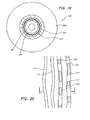
- the hybrid disc must have five annular bands. Radially from the disc center - as is well known, optical discs are normally recorded and read from the center toward the outer circumference - and with reference to the hybrid disc 300 shown schematically in Figure 19 (with bands of arbitrary radial width) the first is the R1 band 301, which allows the CD-R recorder to optimize its nominal write laser power. Next is the ROM1 band 302, the "PMA" (program management area), which typically comprises only up to a few disc turns. This band contains information on the number of tracks in the disc, and its purpose is to close the disc after recording. Next, in succession, are selectively wide R2, ROM2 and R3 regions, 303, 304, 305, respectively, the last of which may extend nearly to the outer circumference of the disc.
- a hybrid disc master must be created with the requisite sequential ROM and R bands.
- the ROM data are recorded in an optical recording layer on a surface of a blank master, whose substrate can be any convenient material, such as polycarbonate or glass, for typical first surface ("from the top") recording, as described below.
- the substrate must, of course, be transparent for disc masters created by second surface recording.
- the ROM data can be encryption data or anything else the manufacturer wishes to record in the ROM region(s).
- the R bands of the disc master will display the spiral tracking pre-groove.
- the entire disc master will be provided with ATIP timing information in a conventional manner.
- the hybrid disc master is typically created by one of two methods, respectively the photoresist (“PR”) process or the dye-polymer process.
- PR photoresist
- Other disc mastering processes may exist and doubtless others will arise in the future, but this discussion will concentrate on these two methods, of which the PR process is presently the more commonly employed.
- the Photoresist (“PR”) recording method is essentially a photographic engraving process.
- the recording surface of the hybrid disc master comprises a thin, photosensitive polymer resin layer of substantially uniform composition, which has exposure characteristics virtually identical to those of photographic film emulsions.
- PR is a purely photochemical (i.e., optical) method of optical data recording.
- PR it is not the quantity of heat instilled in a selected small portion of the disc surface that exposes the photoresist; it is merely the quantity of incident light that determines if sufficient exposure occurs to enable formation of the desired three-dimensional features.
- a threshold quantity of light is required to effect initiation of exposure at the photoresist surface.
- the extent and depth to which the photoresist below the immediate surface is exposed depends on the intensity and duration of the impinging write laser light and the optical characteristics of the photoresist material, itself. Because of light absorption and scattering within the photoresist medium, and the development process, the width of the exposure within the medium typically decreases as its depth increases. However, as a general principle it is accurate to say that increasing the incident intensity will tend to increase the depth of exposure within the photoresist medium, assuming the same duration (rotation velocity).
- the radial width of the exposure (particularly at the surface) is determined by the write beam width, it being understood that the beam cross-section may be thought of as an Airy disc, with a Gaussian distribution of intensity, radially. Since PR is a purely optical process, exposure begins and ends instantly, as the write beam is, respectively, activated and deactivated for each write pulse, as the disc rotates beneath the beam.
- the hybrid disc master When the entire ROM area and the R band spiral track (or collection of concentric tracks) are “exposed” onto its surface, the hybrid disc master is "developed,” as in the case of ordinary photographic film. In this step, an etching solution is introduced to dissolve and remove the exposed regions of resist (or the unexposed regions, depending upon whether a positive or negative resist is used), which creates a succession of a very large number of narrow, three-dimensional, typically elongated microscopic pits and intervening lands in the ROM bands and spiral pre-grooves in the R bands of the hybrid disc master.
- the width (i.e., transverse extent) of these ROM features, at the disc surface will be essentially identical to the effective width of the write beam, as will the disc surface width of the pre-grooves in the R bands. Below the surface, the width of each pit and pre-groove will decrease.
- the interval between each successive pair of transitions individually represents a quantum of data corresponding to a particular data packet (i.e., pulse) in the original EFM (or EFM Plus) signal.
- the thickness of the photosensitive data layer (deposited on the much thicker glass or polycarbonate substrate) is usually selected to be identical to the desired ROM pit depth.
- the thickness of the photosensitive data layer is usually selected to be identical to the desired ROM pit depth.
- the thickness of the photoresist layer and the exposure level - and thus the resulting pit (or pre-groove) depth - are normally selected for optimal detection from replicas in a manner well known by those skilled in the art.
- pit and pre-groove width are determined by the power and effective width of the recording beam. The latter is determined by the wavelength of the write laser utilized and the numerical aperture ("NA") of the focusing means, in a conventional manner.
- NA numerical aperture
- the transverse sectional shape of the pit may be controllable, to at least some degree, by the optical characteristics of the photoresist material, the etching process, the power of the write beam and the particular focusing configuration selected, as described in the patent literature.
- the length of each resulting ROM pit will be primarily determined by the duration of the corresponding EFM (or EFM Plus) data pulse, as will be the length of each intervening land.
- the PR method is essentially an etching process, and even if the photoresist is fully exposed, a certain amount of roughness inevitably occurs on the pit sidewall surfaces. While this has not proved to be a particularly significant problem in ordinary CD-ROM mastering applications, the PR method of disc mastering is unconducive to production of hybrid CD masters from which hybrid CDs can be rapidly manufactured with a low rejection rate.
- dye-polymer recording is a thermal process, proceeding on the basis of physical principles quite different than those underlying PR.
- this thermal process requires a fairly sophisticated write strategy. This is because in the dye-polymer case, a small amount of time is required, after the beam is activated at the beginning of each pit formation, as the disc master rotates, to heat the dye-polymer to its thermal threshold. This causes a tapered leading edge of the resulting pit. On the other hand, cooling occurs almost instantly when the beam is shut off, resulting in relatively blunter trailing edges.
- dye-polymer disc mastering requires careful modification of the EFM pulses to counteract these thermal effects.
- the '129 Patent addresses this problem and teaches an effective dye-polymer mastering write strategy, while the Parent Application non-exclusively identifies various equivalents.
- Hybrid CD or DVD mastering by the dye-polymer process comprises selective expulsion of the photo-thermally active recording layer of the hybrid disc master, to yield a succession of pits and intervening lands, each representing data, in the ROM bands, and yielding pre-grooves in the R bands.
- This recording layer comprises a mixture of a polymer (e.g., nitrocellulose) and a dye whose color is complementary to that of the (typically, laser) write beam to promote maximum heat absorption.
- the proportion of dye in the dye-binder mixture should be sufficient to obviate the need for excessive write laser power, while low enough to minimize the effects (e.g., noisy readings from the final hybrid disc) that might result from dye residue on the surface of the hybrid disc master.
- the proportion of dye in the dye-polymer mixture is generally quite low, with a preferred range of approximately 3-5%.
- the selection of the dye color would proceed according to generally understood principles, based on the particular type of write beam selected.
- the desired HF optimization is achieved with an effective pit depth (noting that each pit will normally posses a curved base, caused by the dye-polymer expulsion processes) equal to ⁇ /4, where ⁇ here is the wavelength of the (typically, laser) read beam within the substrate material (since discs are normally read from the second surface).
- ⁇ is the wavelength of the (typically, laser) read beam within the substrate material (since discs are normally read from the second surface).
- ⁇ is the wavelength of the (typically, laser) read beam within the substrate material (since discs are normally read from the second surface).
- This will create a ⁇ (180°) phase shift in the reflected light, effectively canceling out; by interference, the small proportion of incident light not already scattered away by diffraction.
- nearly 100% of incident light is reflected from the essentially flat land areas. It can easily be seen, then, that with ⁇ /4 effective pit depth the change in reflected light detected at each pit/land transition will be very abrupt, thus facilitating accurate detection of pit and land length
- PP detection generally measures the quantity of light diffracted from the pit at an angle in respect to the vertical direction. This is normalized with the known or observed reflectivity of the disc surface, to provide comparative values in the particular context.
- radial PP detection is merely an amplitude comparison of detected light on either side of the longitudinal track axis (whether within a pit, land area).
- the PP servo moves the read beam in the opposite direction, radially, until detection in the two halves is equalized, indicating proper tracking.
- the proposed solution is to maintain the intensity of the write beam between write pulses at a level just above the thermal threshold of the moving medium. This creates a narrow, shallow groove in the land area connecting successive pits, which essentially increases PP tracking signal strength between pits with hopefully little negative effect on HF (i.e., pit/land transition) detection accuracy.
- the method taught there would superficially seem to satisfy the PP optimization criteria, in that the land groove can be made to be approximately ⁇ /8 in effective depth (in the hybrid disc case, its effective phase depth would be approximately ⁇ /8).
- the resulting land groove must necessarily be quite narrow.
- this actually compromises PP detection because another feature of the PP/HF dichotomy is that optimal PP detection is realized with a groove that is wider than one that would optimize HF detection.
- HF detection is not significantly addressed by Schoofs. Indeed, the logical extension of the Schoofs teachings would be to further increase beam intensity between pits to widen the groove for hopefully better tracking. But that would actually compromise PP detection by deepening the groove and would also compromise HF detection by causing pit/land transitions to be more difficult to detect, thus negatively counterbalancing any proposed PP improvements.
- Creating a disc master by whatever method e.g., the PR method or a thermal method, such as the dye-polymer method), and in whichever format (CD-ROM, hybrid CD, etc.) is only the first step in the disc production process. It is the final disc that is of principal interest, not the disc master. The final disc, to which the manufacturing specifications are addressed, is not obtained until a number of intermediate steps have been taken in the manufacturing process.
- the hybrid disc master is converted to a metal stamper by conventional galvanic processes, and polycarbonate daughter discs are molded from it. If sufficient skill and care are exercised, the stamper will be a virtually exact mirror image of the master, and the resulting "clear replica" hybrid discs will likewise be virtually exact copies of the master. They will display the recorded ROM data in the ROM bands, and will display the necessary CD-R pre-groove in the R bands.
- the Figure of Merit is a weighted function that measures overall conformity to the applicable specifications, such as the amplitude of HF detection, the amplitude of PP detection, minimization of cross talk between radially adjacent portions of the data track, etc.
- the Figure of Merit is increased as the observed parametric values of the final hybrid discs within the relevant specification categories are brought closer to the center of the acceptable ranges of each of those categories, and maximized where only a lower limit applies.
- the CD track pitch is between 1.5 and 1.7 microns, the nominal value being 1.6 microns.
- the length of an EFM-coded CD pit measured at half-depth (where all widths and lengths are conventionally measured), is nominally 0.3 micron per T, where the pit length spatially represents an input data pulse run length of nT temporal duration.
- the width (“PW") of a CD pit (again, measured at half depth, as shown in Figure 18) and the spot diameter of the write beam creating it are each approximately 0.5 micron, i.e., approximately TP/3.
- the read beam is approximately double that width, or about 1 micron wide.
- the spot diameter, d is determined by the formula d ⁇ 0.5 ⁇ /NA, where ⁇ is the beam wavelength in vacuo, NA is the numerical aperture and d is the diameter of the resulting spot.
- ⁇ 0.780 micron
- NA 0.45
- Double-sided (or layered) discs can be generated by utilizing two molds - one for each side (or layer) - each made from a separate disc master, recorded in the manner discussed above.
- the final steps in hybrid disc manufacture are spin coating, onto each clear replica hybrid disc, a thermally-active recording layer; overcoating that layer with a thin, metallic reflective layer; and, normally, applying a protective layer above the latter.
- the recording layer will, of course, tend to fill in portions of the ROM data pits (particularly, those of shorter run lengths, e.g., 3T to 5T, as discussed below) and intervening lands, as well as the R band pre-grooves.
- the depth of the resulting optical recording layer above the ROM pits and the R band pre-grooves depends on a host of factors, e.g., the viscosity of the layer before drying, the drying conditions, the spin velocity and the transverse shapes of the pits and pre-grooves.
- the final hybrid discs, as well as later-recorded hybrid discs must, in their entireties conform to the Orange Book specifications, and their ROM areas must also conform to the Red Book specifications, insofar as they are incorporated into the Orange Book specifications.
- the Nakagawa hybrid disc patent (U.S. 5,204,852), mentioned above, is based on photoresist recording of ROM data pits and R band pre-grooves (Column 5: lines 3-20), and teaches exposure of the photoresist in the ROM area at a different level than in the R band area.
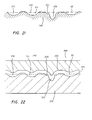
- Two basic embodiments are taught: one displaying a pre-groove with a triangular transverse section, the other displaying a rectangular transverse section. Both embodiments of the pre-groove are shallower than the ROM data pits, because the photoresist is not fully exposed while the pre-grooves are created.
- this partial exposure of the photoresist would generate the triangular-section pre-groove of the first Nakagawa embodiment.
- Nakagawa proposes to generate the rectangular section pre-grooves In fact, this would be very difficult, if not literally impossible, to accomplish by the means taught. While some light scattering may occur within the photoresist, the exposure cross-section would tend to narrow from the disc surface downward, most likely yielding the typically observed trapezoidal profile.
- Nakagawa offers a third embodiment (Column 11, line 66 to column 12, line 36), in which a first beam exposes the photoresist to (hopefully) create the rectangular-section pre-groove, and a second beam then partially exposes the entire R band with the hope of reducing the effective depth of these pre-grooves. It will perhaps be appreciated that this double exposure of the photoresist would, at best, be a very difficult process to control. As with the second embodiment, no teaching is given as to how this might be accomplished.
- the depth of the thermally-active recording layer applied over the R band pre-grooves must be greater than over the pits already recorded in the ROM band(s). This is to ensure that the resulting pits selectively recorded in the R band(s) will have the same effective optical depth as those already existing in the ROM section, after the spin-coated recording layer that spreads across the entire disc has covered them. Accordingly, Nakagawa suggests that the cross-sectional shape of the respective features will ensure that when the thermally-active recording layer is spin coated over the clear replica hybrid disc, the proper respective depths will be achieved. This would be very unlikely to occur if the pre-grooves have a triangular cross-section.
- Yanagimachi U.S. Patent 5,696,758
- another photoresist mastering method essentially attempts to follow the Nakagawa teachings.
- exposing the photoresist less in the R bands than in the ROM bands as Nakagawa teaches, and further by employing an exposure level in the ROM lands that is less than the exposure level of the ROM pits, Yanagimachi creates grooves in the ROM area of the clear replica hybrid disc that are narrower and shallower than the pits which they "connect.”
- the thermally-active recording layer is then spin coated over the clear replica hybrid disc to create the final hybrid disc, there will be even less of the ROM groove remaining.
- Yanagimachi does not teach how to independently control the width and depth of the ROM grooves, the ROM pits and the R band grooves.
- One of ordinary skill would know that if a PR generated feature is narrowed by reducing the laser power of a single beam, its depth would be correspondingly reduced.
- Yanagimachi which definitely teaches the use of a single beam (Column 6, lines 23-32), offers no assistance in this regard.
- the Yanagimachi teachings are, if anything, even less instructive than those of Nakagawa in enabling those of ordinary skill to manufacture hybrid discs that might meet Orange and Red Book specifications.
- Ha (U.S. Patent 6,212,158) differs from Yanagimachi primarily in certain parametric values. Specifically, Yanagimachi specifies a ROM pit depth between 250 and 350 nanometers with a ROM groove depth between 30 and 170 nanometers, while Ha specifies a ROM groove depth of more than 170 nanometers. Indeed, Ha refers to Yanagimachi, pointing out (Column 1: lines 36-43) the difficulty in creating acceptable hybrid discs incorporating the latter's wobbled, depth modulated (ROM area) groove. Accordingly, Ha modifies Yanagimachi with different parametric values, based on a very similar concept, and Ha's claims are essentially "written around" Yanagimachi. But Ha adds nothing material to the foregoing two teachings to facilitate hybrid disc production.
- the present invention aims to provide master hybrid CD and DVD discs, and master hybrid discs of other formats (e.g., CD-RW), including those with even greater data density, from which hybrid discs meeting all applicable specifications may be reliably produced in a high-speed commercial manufacturing environment by those of ordinary skill. Accordingly, it is an aim of this invention to provide apparatus and a method by which such master hybrid discs may be efficiently created. It is likewise an aim of this invention to provide a method of creating such hybrid disc masters by a thermal mastering process.
- the present invention may provide a hybrid disc master ROM in which pits are recorded in ROM grooves that are wider, in transverse extent (as defined below), and shallower than the ROM pits, the ROM lands typically comprising those portions of these ROM grooves intervening between consecutive ROM pits.
- the ROM pits may be up to 110% as wide as the ROM grooves, when each are measured at half depth.
- both ROM grooves and R band grooves are provided in the hybrid disc master, each being wider than the ROM pits, the ROM grooves and R band grooves typically constituting one continuous spiral groove extending through both the ROM and R regions.
- a dual beam recording apparatus produces the hybrid disc masters, according to the preferred embodiment of the invention.
- the intensity of the individual beams, and their diameter at the hybrid disc master surface may be individually selected, so that the groove and pit configurations in the master may be chosen and optimized to ultimately yield in-spec final hybrid discs.
- the beam creating the ROM groove will lead the beam creating the ROM pits, as the master disc revolves.
- the two beams will coincide, or the groove-creating beam will lag the pit-creating beam.
- the invention in most embodiments, utilizes a thermal mastering process. This will ensure that the pit and groove surfaces will be smooth and sloped, thus further facilitating efficient, high-speed clear replica molding.
- the berms that would tend naturally to form at the radial extremities of the pits and grooves in the hybrid disc masters, by the natural expulsion processes inherent in thermal mastering, are reduced or even eliminated. This further facilitates production of final hybrid discs meeting all applicable manufacturing specifications. This is accomplished, in the preferred embodiment, by causing one beam to create the pits, while the second beam, whose beam width at the surface is relatively wider than the first beam, but whose intensity is less, to minimize or even to eliminate the berms as they have been, or would otherwise be, created.
- the latter second beam is activated during the entire creation of a ROM band, while the first, more intense and narrower beam, is activated and deactivated in response to data-based beam modulation, resulting in a succession of ROM pits and lands, where the lands are a continuation of the groove in which the relatively narrower pits reside.
- a single, dithered beam is utilized, where both the instantaneous beam intensity and its dither pattern are controlled so that, in effect, such a dithered beam duplicates a dual beam.
- the present invention may provide a hybrid structure comprising:
- the hybrid structure of the invention in its first aspect may be such that the transverse extent of said first feature does not exceed the transverse extent of said first track.
- the width of said first feature, measured at half depth is preferably not more than approximately 110% of the width of said first track measured at half depth.
- the transverse extent of said first track is substantially identical to the transverse extent of said second track.
- the said first track and said second track may comprise one substantially continuous track.
- the hybrid structure according to the invention in its first aspect may be such that it includes one, some or all of the following features:
- At least a portion of said first track and at least a portion of said second track together comprise a substantially continuous spiral.
- the hybrid structure may comprise a successive plurality of said first principal features, preferably with each said first principal feature comprising a principal pit in said surface, and preferably each successive pair of principal pits interspersed with a principal land, and preferably each said principal pit and each said principal land separately representing a respective quantum of said stored data.
- each of said principal lands of the hybrid structure comprises a three-dimensional indentation into said surface, having a microscopic principal land transverse dimension and a microscopic principal land vertical dimension.
- the transverse extent of each of a successive plurality of said principal lands substantially equals the transverse extent of the respective pair of principal pits between which such principal land intervenes.
- the transverse extent of each of a successive plurality of said principal lands may exceed the transverse extent of the respective pair of principal pits between which such principal land intervenes.
- the hybrid structure may be such that:
- the longitudinal extremities of each of said principal pits of the hybrid structure may be mutually geometrically symmetric.
- the longitudinal extremities of each of said principal lands of the hybrid structure may be mutually geometrically symmetric.
- each of said principal pits has an outer shape, defined by a transverse section thereof, displaying no substantial slope discontinuity from the point at which said principal pit begins its displacement in said first vertical direction from said surface, at one transverse edge of said first feature, until the point at which said displacement from said surface ends at the opposite transverse edge of said principal pit.
- the present invention may provide a hybrid structure comprising:
- the width of said first feature, measured at half depth is preferably not more than approximately 110% of the width of said first track measured at half depth according to the second aspect of the invention.
- the invention may provide a hybrid structure wherein the transverse extent of said first track is substantially identical to the transverse extent of said second track.
- the hybrid structure may be such that said first track and said second track comprises one substantially continuous track.
- the present invention may provide a parent hybrid disc structure comprising:
- the present invention may provide a hybrid structure comprising:
- the present invention may provide a hybrid structure comprising a first region and a second region,
- the hybrid structure in its sixth aspect may include one, some or all of the following features:
- Each of said principal lands of the hybrid structure preferably comprises a three-dimensional indentation into said surface, having a third transverse dimension.
- the extent of said third transverse dimension may be substantially equal to that of said first transverse dimension.
- the extent of said third transverse dimension may exceed that of said first transverse dimension.
- the hybrid structure may be such that:
- each of said principal pits has an outer shape, defined by a transverse section thereof, displaying no substantial slope discontinuity from the point at which said pit begins its displacement in said first vertical direction from said surface, at one transverse edge of said first feature, until the point at which said displacement from said surface ends at the opposite transverse edge of said principal pit.
- the present invention may provide a parent hybrid disc structure comprising a first region and a second region,
- the present invention may provide a method of producing a hybrid structure comprising a first region and a second region, said first region storing selectively retrievable data in a first track of successive quanta of said data, each said quantum of stored data represented, in said hybrid structure, by an elongated, microscopic three-dimensional principal feature, said principal feature having a first longitudinal dimension along said first track, a first transverse dimension normal to said first longitudinal dimension and co-planar therewith in a first plane, and a first vertical dimension normal to said first plane, said second region comprising a second track, said second track having a second longitudinal dimension, a second transverse dimension normal to said second longitudinal dimension and co-planar therewith in a second plane, and a second vertical dimension normal to said second plane, said transverse and vertical dimensions each microscopic in extent, the extent of said second transverse dimension greater than that of said first transverse dimension, and the extent of said first vertical dimension greater than that of said second vertical dimension, said method comprising the steps of:
- the method may provide that a single optical beam is provided, said second optical means comprising means to cause said beam to selectively dither along said transverse direction.
- the method may provide that said provided structure comprises a surface whereon said principal features and said second track may be imposed by optically-induced thermal means, said first and second optical means selectively inducing, thermally, said principal features and second track on said surface.
- the present invention may provide an apparatus for producing a hybrid structure comprising a first region and a second region, said first region storing selectively retrievable data in a first track of successive quanta of said data, each said quantum of stored data represented, in said hybrid structure, by an elongated, microscopic three-dimensional principal feature, said principal feature having a first longitudinal dimension along said first track, a first transverse dimension normal to said first longitudinal dimension and co-planar therewith in a first plane, and a first vertical dimension normal to said first plane, said second region comprising a second track, said second track having a second longitudinal dimension, a second transverse dimension normal to said second longitudinal dimension and co-planar therewith in a second plane, and a second vertical dimension normal to said second plane, said transverse and vertical dimension each microscopic in extent, the extent of said second transverse dimension greater than that of said first transverse dimension, and the extent of said first vertical dimension greater than that of said second vertical dimension, said apparatus comprising:
- thermal process refers generally herein to any process by which controlled, thermally induced microscopic changes may be made in a medium, in the context of hybrid disc mastering.
- an optical (e.g., laser) or quasi-optical (e.g., ion or electron) beam causes formation of a three-dimensional feature in or on a layer of substantially uniform composition as the result of heat locally generated by the beam.
- This is in contrast to a purely optical method, such as the PR method, where it is the quantity of light that ultimately effects formation of the feature, rather than heat generated by the beam.
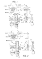
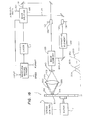
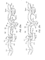
- Figures 1 and 2 are simplified depictions of the apparatus employed in creating the hybrid disc masters, offered primarily to illustrate its overall configuration. Additional elements of the apparatus, relating specifically to use in hybrid disc mastering, are illustrated in Figures 13-17, and will be discussed in connection with those figures.
- the hybrid disc master 1 on which the ROM data pits and intervening lands are recorded is rotated by a spindle motor 3, which is controlled by a speed controller 5.
- a gas laser 7 forms a write beam 9 of a particular wavelength.
- the write beam passes through an external optical modulator 11, which varies the intensity of the write beam in accordance with a drive signal on line 10, from the waveform shaping circuit 31.
- the optical modulator 11 might, for example, comprise an AOM or, a faster-response EOM (electro-optic modulator).
- the modulated beam 13 is directed to the disc master 1 and is focused to a spot 15 on the active surface 43 by appropriate optics, as generally described above.
- optics preferably include an objective lens 17 and a beam expanding (i.e., condenser) lens 19, which spreads the modulated beam 13 to fill the aperture of the objective lens 17.
- NA numerical aperture
- the numerical aperture ("NA") of the objective lens is chosen so that the diameter of this spot will be approximately 0.5 micron (in the case of CD recording), which is comparable to the wavelength of typical laser beams now employed.
- the lenses are mounted on a carriage 21 to allow radial movement of the spot 15 relative to the center of the disc 1. This is accomplished by means of a generalized translational drive system 23, whose details would be well within the skill of the ordinary practitioner.
- Figures 1 and 2 illustrate radial movement of the spot 15 controlled by a translational system 23 that moves, while the axis of rotation of the hybrid disc master remains stationary
- the carriage position could be fixed, in which case the disc apparatus would be moved to cause the axis of rotation of the disc to be translated radially, in synchronization with the timing parameters of the writing process.
- the beam would be continuously moved, relative to the center of rotation of the disc, to generate the desired narrowly spiral data track(s).
- the drive signal for the optical modulator 11 is formed by the waveform shaping circuit 31, as described in the '129 patent, whose purpose is to convert the sequence of EFM-coded data pulses and intervening "off" spaces into a resultant sequence of spaced drive pulses, the trailing regions of which each display a moderated decline in amplitude.
- This moderated decline may, for example, comprise a linear ramp, an exponential decay, a series of steps of progressively declining amplitude or a double-step (where the intermediate step is perhaps at half the "on" amplitude at the initiation of the trailing region).
- moderated decline profiles may also be employed in the trailing region, it being understood that the purpose of any moderated trailing region decline is to cause heat generation in the active dye-polymer layer 43 at the trailing end of formed pits to decrease more gradually than would otherwise result if these drive pulses displayed a single abrupt drop in amplitude from the "on" write level to the "off' base level.
- every moderated trailing edge decline profile promoting that desired result will herein be interchangeably referred to as a "ramp.”
- trailing edge ramp is described in the '129 patent as causing the trailing ends of the formed data pits to become tapered, as the latter term is broadly defined above.
- the leading ends of the pits will already be tapered because a certain brief passage of time is required after the leading edge of a laser pulse (i.e., initial activation of the spot 15 at the active layer 43) before the full heat buildup is felt in that rapidly moving medium.
- This leading end taper can be blunted somewhat by boosting laser power at the pulse leading edge, as is commonly done, although it is essentially impossible to entirely eliminate it.
- a progressively broadening taper will form at the leading edge of the pit after the corresponding drive pulse is initiated.
- the waveform shaping circuit 31 includes an input 33 for receiving the data to be recorded and may also include another input 35 for receiving a drive signal bias control for adjusting the average intensity of the modulated beam 13. Since the rotational speed of the disc varies in order to maintain constant linear speed of the spot 15 relative to the disc, the signal processing system may include a third input 37 for receiving a signal indicative of the instantaneous relative speed, perhaps generated from the speed control 5.
- the hybrid disc master 1 will generally include a substrate 41 and the active (dye-polymer) layer 43 coated onto the substrate.
- a transparent member 45 may be interposed between the active layer and the objective lens 17 to prevent dust and other contamination from settling on the active surface.
- the active layer may be formed on the inner surface of the transparent member, or any other convenient configuration of elements in the hybrid disc master 1 may be chosen according to particular circumstances and preferences, which may feature first surface recording, as shown in Figure 1, or second surface recording.
- Figure 2 is identical to Figure 1 except that Figure 2 illustrates the configuration that might be employed if a diode laser 7' were utilized. Since a diode laser can respond virtually instantaneously to its drive signal input, no external optical modulator is required in this application. Rather, the output from the waveform shaping circuit 31' may, through line 10', constitute the direct drive signal for the laser 7'. Here, the modulated beam 13' is directly emitted from the laser 7'.
- a single waveform shaping circuit 31 is shown.
- a plurality of waveform shaping circuits 31', or a plurality of sub-circuits within the waveform shaping circuit could be utilized.
- These components could be summed by an intermediary element (not shown) or they could all be fed into the laser 7' through line 10', allowing the laser itself to act as a summing element.
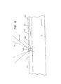
- FIG. 3 illustrates single beam (PP) tracking, in reference to the hybrid disc master, the final hybrid disc or a CD writer recording onto the latter.
- a single read beam 60 is utilized as the light source for HF (in the hybrid disc) and PP detection.
- the reflection of this beam is suitably passed to a conventional detector (not shown), in which the reflected beam is split into two equal, semi-circular components, separated by a division that is parallel to the tracking direction of the beam.
- HF detection comprises observing the instantaneous amplitude of light reflected perpendicularly from the disc surface - by summing the output of the two detector components - and pit-land transitions are registered when the quantity of detected light reaches an established value.
- PP detection comprises comparison of the light diffracted from the disc surface, as received in the two detector components, by subtracting the output of one detector component from that of the other, to produce a servo feedback to move the read beam radially until the two halves produce equal readings.
- Figure 3 shows that the diameter of the read beam 60 is approximately double the width of the pit 50, as is generally the case.
- FIG 4 illustrates the triple-beam tracking system commonly employed in those CD players, where three beams 61, 62, 63 are utilized.
- the central beam 61 is merely the read beam, corresponding to the read beam 60 in the single beam tracking system illustrated in Figure 3.
- the forward beam 62 is offset by approximately 1 ⁇ 4 of the track pitch, TP, to one side of the tracking axis of the tracking apparatus, while the rear beam 63 is offset by an identical amount to the other side.
- TP the radial axis-to-axis distance between adjacent data tracks or track portions, is generally about three times the pit width, as shown.
- the reflection from central beam 61 is not split, and serves only for HF detection and, in some systems, focusing.
- Tracking detection from the tracking sensors associated with the other two reflections is compared, and appropriate radial adjustment is made continuously until the tracking axis aligns with the longitudinal axis 64 of the track of pits. Since HF and tracking detection with single-beam and triple-beam configurations are well known in the art, the respective apparatus need not be illustrated or further discussed.
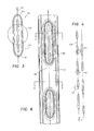
- Figure 5 illustrates the sectional configuration of a ROM pit 50 produced in the hybrid disc master created by the dye-polymer method just described. It will be noted that berms 70a, 70b rise above the surface 68 of the disc. As explained above, this is a natural consequence of the plasticization component of the expulsion process by which these pits are created. It will be noted that the presence of these berms changes the effective phase depth of the pit. Optimization of the hybrid disc mastering parameters, based on this configuration, may yield final hybrid discs offering effective HF detection with a reasonable tracking signal. But because of dichotomy between PP and HF detection requirements, recording beam intensity must be set so that in the final hybrid discs the effective pit phase depth is approximately 3 ⁇ /16. But this optimizes neither HF detection (requiring a ⁇ /4 effective phase depth) nor tracking (requiring a ⁇ /8 effective phase depth).
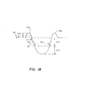
- Figure 6 illustrates the improved configuration of ROM pits and intervening lands in the hybrid disc master, implemented by the preferred embodiment of the present invention. It will be seen that here a relatively wide, shallow groove 75 is provided, running along the longitudinal axis of the sequence of pits and lands, within which are the sequence of ROM pits themselves. The width of this groove is greater than that of the ROM pits.
- This relatively wide groove of the present invention is in clear contrast to the narrow inter-pit groove taught in Schoofs, and the similarly narrow grooves to connect succeeding pits taught in the Nakagawa, Yanagimachi and Ha references, discussed above, whose intended purpose appears to be to facilitate tracking, but which, on account of their resulting dimensions, according to the other teachings of those references, would actually fail to accomplish this purpose to any meaningful extent.
- This advantage of ROM pit, ROM groove and R pre-groove mastering flexibility offered by the present invention will result in high quality final hybrid discs, when the manufacturing process is optimized, as discussed below.
- While provision of a relatively wide, shallow ROM groove of selective dimensions by the present invention will facilitate tracking - at least far more readily than in the prior art - its principal function is to provide increased R band pre-groove volume to offer flexibility in application of state-of-the-art high-speed recording dyes in accordance with manufacturers' instructions, which often specify preferred groove configurations in order to obtain the manufacturer's recording speed certification.
- One such high-speed dye currently popular among CD-R manufacturers, is Ciba Ultragreen MX. The specifications and instructions for use of this particular dye are available upon request to Ciba, a well-known source of CD-R dyes.
- the present invention provides independent control of groove width and groove depth, through use of two independently controllable beams, or a dithered beam, thus providing the flexibility needed to satisfy all of these requirements. Indeed, the present invention allows independent control and optimization of the transverse configurations of all the features.
- PP tracking in the hybrid disc is facilitated by the increased width (but controlled depth) of the ROM groove, which will be seen by a CD player's single beam detector in the same manner as a wider pit would be seen.
- HF detection from the hybrid disc can be independently improved by providing optimal, relatively narrower and deeper pits, without regard to the conflicting requirements of PP tracking, which may now be independently optimized by provision of the wide, shallow groove.
- Such narrower pits within relatively wide, shallow grooves offer the additional benefit of reducing HF cross talk in the hybrid disc between radially adjacent data tracks. Independent optimization of HF and PP detection, and reduction of cross talk, are important results enabled by this embodiment of the invention.
- the berms 70a, 70b can be greatly reduced in height, if not entirely eliminated, as shown in Figure 7.
- This provides a ROM pit shape in the final hybrid disc whose effective phase depth could be made to coincide more closely with the optimal ⁇ /4, than might be possible without the improvements offered by this invention.
- the HF detector would see the bottom of a groove corresponding to the bottom 77 of the groove 75 in the disc master as it would otherwise have seen the final hybrid disc surface, itself, and would thus see a practically berm-less pit of the proper width and an effective phase depth providing the desired ⁇ phase shift.
- the PP detector would see, in the final hybrid disc, a "tracking feature" with a desirably greater width, and whose effective phase depth is closer to the ⁇ /8 required for the optimal ⁇ /2 phase shift for PP detection.
- Figure 7 shows that the ratio of the height h of the berms 170a,b to the depth d of the pit 50 in the hybrid disc master is considerably less than in the section shown in Figure 5, which does not incorporate any of the improvements of the present invention.
- These vertical dimensions are measured from the vertical index level of the point 177 at which the right berm 170b begins to rise above the groove level 77.
- Figure of Merit by providing a wide, shallow tracking groove for improved PP detection without compromising HF detection of the ROM pits themselves
- the reduction in berm height thus realized, also facilitates accurate replication from the hybrid disc masters by reducing the quantity of material that might tend to cling to shallower crevices displayed in the resulting stampers. This is a very important advantage of the invention, in respect to the PR-based concepts disclosed in the cited references.
- the groove 75 itself, could continue in the land areas of the track of pits and lands, to ultimately provide a corresponding feature in the final hybrid disc having an effective depth of ⁇ /8, facilitating tracking between pits by providing a wide, relatively flat bottom 77 of the groove of consistent depth through its entire width, as shown in Figure 8.
- Virtually berm-less pits 50 may be created by adjusting the parameters to cause a slight increase in groove width in the hybrid disc master, together with a corresponding slight increase in the width of the ROM pits formed within the groove.
- These parameters include beam intensities and diameter, which may be adjusted individually or jointly to achieve the following results.
- Figure 9 illustrates the latter embodiment of the invention.
- the hybrid disc master there is no ROM groove at all, except in the land areas, and the resulting ROM pit 50 is rendered essentially berm-less, and with a shallower slope on either side. That facilitates PP tracking without compromising HF detection, in the final hybrid disc. Tracking detection is improved because the shallower side slopes tend to reflect a greater proportion of incident light away from the vertical. Yet HF detection is not compromised at all, because effective pit depth is maintained at the conventional 3 ⁇ /16. The net result is an overall improvement in Figure of Merit, which is a benefit of the present invention.
- Figure of Merit in CD hybrid disc mastering applications may be improved by the present invention even without the added PP-facilitating groove.
- a groove-less, berm-less profile, as shown in Figure 9 would be nearly ideal for the R band pre-grooves, whereas the embodiment shown in Figure 7 might not be as desirable for that particular application.
- Recording R band pre-grooves would simply require a fixed intensity of each write laser beam, rather than a data signal modulation of either beam intensity.
- the mode of driving the write laser to record the various features can be selectively programmed, in a conventional manner, to suit the particular requirements of the specific sequence and the prescribed characteristics of the ROM and R bands being recorded.
- R band pre-groove is simply a groove of selective dimensions, recorded in the R band(s), as will be discussed below.
- the ROM groove 75 could be implemented along the entire track of ROM pits and lands by splitting the write beam 13, 13' into two beams impinging on the active surface 43 of the hybrid disc master 1 while the latter is spinning.
- the groove-writing beam could be activated only during land periods (i.e., from the end of the trailing region decline of one pit-writing pulse until the initiation of the leading edge of the next pit-writing pulse).
- the groove-writing pulse could be selectively activated and de-activated at any times and for any durations during the pit writing process, as conditions and preferences might dictate.
- Figure 10 illustrates the situation, in the hybrid disc master, where the principal ROM pit writing beam 102 and the ROM groove writing beam 103 are superimposed, so that the data marks are created simultaneously with the groove within which they are contained.
- a succession of pits 50a,b,c and intervening lands 65a,b are formed within the optically-active layer 112 supported by the substrate 41 of the disc 1.
- the pits are entirely within the formed groove 75, i.e., the upper surfaces of the pits are within the groove and are below its upper surface 114 (the unrecorded surface of the disc).
- the land portions 65a,b of the data track are likewise contained within the groove.
- the groove-writing beam is "on" during the entire recording process.
- the groove-writing beam might selectively be activated only during the period between formation of successive pits, to form only grooved land areas 65 along the data track. This would have no effect on the HF or tracking of the pits, but tracking between pits, i.e., in the land areas, would be improved for the reasons discussed above.
- Alternative embodiments might involve selective formation of the groove by correspondingly controlled input to the means by which the groove-writing beam is created, as will be discussed below.
- Figure 11 differs from Figure 10 only in that in Figure 11, the groove-writing beam 103 leads the principal writing beam 102.
- This configuration shown in Figure 11 presently appears to provide the best results in hybrid disc mastering according to the present invention. In all other respects, this embodiment is similar to that illustrated in Figure 10, and all comments in reference to Figure 10 apply equally to Figure 11.
- Figure 12 illustrates the situation where the principal writing beam leads the groove-writing beam. It will be seen that here the pits are formed prior to formation of the groove in which they will eventually reside. The effect of the later-formed groove is to uniformly expel further material from the formed pits, without significantly changing their configurations. It is as if the already formed pits are pushed down into the newly formed groove, while maintaining their respective configurations.
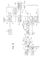
- Figure 13 illustrates the principal embodiment of the invention, corresponding, in its utilization of a gas laser and external optical modulation, to the apparatus shown in Figure 1 for hybrid disc mastering.
- the output beam from the write laser 7 enters a beam splitter 100, by which it is divided into two beams 120 and 121, respectively.
- Beam 120 is the principal writing beam and beam 121 is the secondary beam, the former being the source of the data writing beam 102, while latter is the source of the groove-writing beam 103.
- the principal beam 120 can be used for creating the ROM pits and can also create the principal component of the R band grooves (or the R band grooves, if no secondary beam is used to alter their transverse section configuration, as mentioned above).
- One input to the beam splitter 100 is a signal 104 defining the desired intensity ratio of the two resultant beams.
- Such beam splitters are well known in the art, and might, for example, be based on (1) half-wave plates in combination with a polarizing beam splitter; (2) an acousto optic deflector ("AOD"); or (3) an electro optic retarder in combination with a polarizing beam splitter.
- AOD acousto optic deflector
- an electro optic retarder in combination with a polarizing beam splitter.
- employing an AOD beam splitter establishes the deflection angle, which results in the desired radial separation, if any, of the two resultant beams at the hybrid disc master surface.
- the principal beam 120 enters an optical modulator 11, whose action is controlled by the waveform shaping circuit 31 described above in the context of Figure 1, and whose effect is also described in that context.
- an optical modulator 11 whose action is controlled by the waveform shaping circuit 31 described above in the context of Figure 1, and whose effect is also described in that context.
- an additional input to the waveform shaping circuit - Format - is shown.
- the latter is merely the input induced by the particular operation in which the apparatus is employed, whether it be data mark formation or cutting of a continuous or discontinuous groove or some other application to which the invention might be applied by those with ordinary skill in the art.
- the nature of the input and the waveform shaping circuitry to process it would be dictated by the particular application, in a manner well within the capability of a circuit designer of ordinary skill, based on these teachings.
- One output from the waveform shaping circuit 31 is a signal 131 directed to the beam splitter 100 to control the extent and timing of the beam splitting operation.
- beam splitting will occur substantially continuously.
- This action could be controlled by the waveform shaping circuit 31, as shown, or by some other input to the beam splitter or by an input to the source of the intensity ratio input to the beam splitter 100. Since the purpose of this input is clear, it is assumed that the ordinary practitioner could easily devise other means to accomplish it.
- the modulated principal beam 122 after emerging from the optical modulator 11, passes through the principal ATIP deflector 150, controlled by ATIP input 151, which introduces the required ATIP modulation into the beam, in a conventional manner (see, also, the discussion in respect to Figures 14 and 20, below).
- the secondary beam 121 may be directed to another optical modulator 123, also controlled by the waveform shaping circuit 31, through line 133.
- the only secondary beam modulation normally required would be intensity and on-off control (both provided by the beam splitter 100) and spot size control (provided by the inverted telescope 130, see below). In that case, no optical modulator 123 would be required or it would be switched off. However, in some formats, further modulation of the secondary beam might be necessary or desirable, hence the provision of this optional secondary optical modulator 123.
- the secondary beam 124 After emerging from the optical modulator 123, the secondary beam 124 is likewise subjected to ATIP modulation by passage through the secondary ATIP deflector 155, controlled by ATIP input 156.
- the modulated beam 124 after passage through the secondary ATIP deflector 155, is directed to an inverted telescope 130, whose purpose is to reduce the diameter of that beam by a desired amount, according to the beam width ratio input over line 132, to generate an output beam 125.
- the effect of the inverted telescope 130 is to cause the spot size of the secondary beam, at the master disc surface, ultimately to be selectively greater than that of the principal beam.
- secondary ATIP deflector 155 can be incorporated into the beam splitter 100, if the latter is implemented as an "AOD" (acousto-optical deflector).
- the ATIP input 156 would, instead, constitute an input to the beam splitter 100, and this input would, together with the ordinary deflection input, cause the emergent secondary beam 121 to display both the desired radial displacement and ATIP wobble.
- the principal beam 120 i.e., the "zeroth order" beam
- the principal beam would still require separate ATIP modulation, necessitating passage through ATIP modulator 150, as in the previous case.
- the primary beam 122 and the output beam 125 are combined in a beam combiner 135, whose purpose is to align the two beams for further processing.
- the beam combiner is entirely conventional, and might comprise a dielectric beam-splitter. Alternatively, a half-silvered mirror set at an appropriate angle (approximately 45°) might be used.
- the two emergent beams are passed through a condenser lens 140, which expands the groove-writing beam 103 (derived from the secondary beam 125) and the data beam 102 (derived from the primary beam 122) and directs both beams to the objective lens 145.
- the inverted telescope 130 has narrowed the modulated beam 124 to generate the output beam 125 directed to the condenser lens 140. Because of this narrowing, the resultant groove-writing beam 103 does not completely fill the input pupil of the objective lens, effectively reducing its NA, with the result that the latter will not be focused into as small a spot as will the data beam 102, which fills the objective lens.
- the relative diameters of the two beams at the disc surface 43 will result in formation of a groove 75 whose width is greater than that of the pits 50, as shown in Figure 6, as the disc 1 is spun by its spindle motor 3, the latter governed by a suitable speed control 5 to ensure constant linear velocity.
- the actual dimensions of the two final beams will depend on the parameters governing their upstream processing, notably in proper selection of the reduction factor of the inverted telescope 130 and the parameters of the two lenses 140,145.
- all or a selective portion of the required optics will be supported by an apparatus (not shown) similar in function and purpose to the carriage 21 shown in Figures 1 and 2 - or some other means for relative radial motion between the beams and the disc axis will be provided, as discussed above - to ensure that the data track is properly positioned on the disc.
- these expedients are certainly within the skill of the ordinary practitioner, based on the teachings herein and in the pertinent art.
- Figure 14 illustrates the same configuration of the invention as shown in Figure 13, but in reference to the apparatus shown in Figure 2, wherein a diode laser is employed.
- the comments made in reference to Figure 13 apply equally to the embodiment shown in Figure 14, except, of course, those made in respect to the optical modulators shown in Figure 13.
- groove-writing beam 103 is focused at the active surface 43 of the disc 1.
- the spot size of the groove-writing beam at the disc surface might be ⁇ 1 - 2 microns.
- a first optical deflector 150 is interposed in the path of the principal beam 122. Its purpose is to selectively oscillate the beam, by action of the input through line 151, to produce a wobbled principal emergent beam 162, which will result in the track-writing beam 102. That ATIP input will, in a manner well-understood by those familiar with CD-R mastering, include all the parameters for a correct wobble to be introduced into the ROM data tracks and R band pre-groove tracks, as discussed above.
- a second optical deflector 155 likewise controlled by the same ATIP input signal (over line 156), similarly induces the desired wobble into the beam 124.
- optical deflectors 150,155 are both AODs.
- both deflections must be carefully synchronized and weighted, and this is best accomplished if the ATIP wobble signal to optical deflectors 150,155 comes from a single source, as suggested above.
- the intensity of a groove-writing beam may be varied to cause the depth of the resulting groove to be correspondingly varied.
- This variation in beam intensity can, for example, be readily accomplished by selective control of the intensity level of the output beam 161 directed to the inverted telescope 130, from which emerges the secondary emergent beam 163. This is done by selecting the laser power and the intensity ratio input to the beam splitter 100.
- the ultimate intensity of the groove-writing beam can readily be selected to provide an effect, in the active layer, which varies from production of a full-depth groove, as above described, to merely a berm-removal expedient.
- the groove that would be created by the groove-writing beam would tend to have a curved base, when viewed in section transverse to the track axis. This is because, like the principal pit-writing beam, the intensity cross-section of the essentially circular beam would approximate an Airy Disc distribution along its diameter, with the greatest intensity nearest its center. In some applications, however, a more flat-bottomed groove, as shown in Figure 8, might be desirable, particularly as this might improve tracking by providing, in the final hybrid disc, a uniformly ⁇ /8 phase depth along the base of the groove.
- Figure 15 illustrates an apparatus for generating such a relatively flat-bottomed groove by causing the groove-writing beam to dither (i.e., rapidly oscillate transversely to the axis of the track of pits) during relative motion of the groove- and pit-writing beams along the track.
- Figure 15 is directed toward the configuration shown in Figure 13, in turn relating to the apparatus shown in Figure 1, employing a gas laser requiring external optical modulation. It is assumed that a practitioner of ordinary skill could easily adapt its teachings to the apparatus shown in Figure 2 (i.e., to the embodiment shown in Figure 14), wherein a diode laser is employed, based on the teachings herein and principles well known in the art.
- Figure 15 is actually a dual-mode apparatus, which can be utilized either for CD or hybrid disc mastering.
- the ATIP signals over lines 151,256 are de-activated, since CD mastering requires no wobble creation.
- the ATIP signals are activated, but the optical modulators 11,123 merely transmit beams of selected constant intensity during all or any portion(s) of the track-forming process.
- the input to the optical deflector 155 over line 260 derives from an ordinary signal combiner 220, whose input is whichever of those signals might be activated at the time.
- the dither input causes the optical deflector to execute a complex oscillation of the secondary beam 124, which is a combination of the relatively slow ATIP wobble and the faster dither.
- This dither input may be provided by a conventional oscillator circuit, synchronized with an output from the waveform shaping circuit 31, in a manner well within the capacity of an ordinary practitioner.
- the output from the beam combiner 135 consists of two superimposed beams that pass through the condenser lens 140 and on to the objective lens 145. Emerging from the objective lens are two beams 191,192.
- Beam 191 (shown in solid line) is the un-dithered beam, which is focused onto the active surface 43 of the disc 1 at point 193.
- the other beam 192 (shown in dotted line) is the dithered beam, which is focused instantaneously at point 194.
- beam 192 since beam 192 is dithered, its point of focus moves rapidly in a radial direction (relative to the disc - i.e., up and down in Figure 15), crossing and re-crossing the focal point 193 of the un-dithered beam 191, reaching point 194', for example. It will be understood by those with ordinary skill in the art that the extreme radial movement of the focal point of dithered beam 192, to either side of the focal point of beam 191, is only of the order of a micron, and that Figure 15 necessarily greatly magnifies this range of movement for clarity.
- a relatively flat-bottomed groove may be created by substituting a diffraction grating (or other ordinary diffractive element, such as a phase grating) for the inverted telescope shown in Figures 13 - 15.
- the grating converts the groove-writing beam 124 from the beam splitter 100 into two images, mutually displaced slightly, which together constitute a single, broadened laser beam impinging on the optically active surface.
- Figure 16 is illustrated in Figure 16, which is based on Figure 14 (a diode laser embodiment) and in which the relative focal positions of the beams are greatly separated for clarity.
- the diode laser embodiment is chosen for simplicity in presentation, it being understood that a gas laser embodiment with external optical modulators could alternatively have formed the basis for Figure 16, since the nature of the beam source is unimportant in the context of this invention.
- the groove-writing beam 124 emerges from the beam splitter 100 and passes through an optical device 200, which, in the preferred embodiment, is a custom-designed diffractive element. Its purpose is to divide the incident beam into a pair of emergent beams 201a,b that are mutually offset slightly. Those with ordinary skill in the art will readily be able to substitute alternative optical devices to accomplish this purpose. As shown in the inset to Figure 16, because these emergent beams each have an approximately Gaussian intensity cross-section, that small mutual displacement results in a joint beam whose intensity profile (in a sectional plot along the displacement axis) is nearly rectangular, as shown.
- Beam 102 is the principal write beam
- beams 202 and 203 are, together, the groove-writing beam.
- These three beams focus, respectively, at points 211, 212 and 213 on the active surface.
- Figure 16 is drawn out of scale to show detail, where in fact beams 202 and 203 would overlap at the active surface, as shown in the inset and beam 102 would focus in the center of that merger. The result, at the surface, if seen microscopically in plan view, extending radially, would be an elliptical light spot whose intensity is greater at the center (where the pit is written) than at either side (by which the groove is created).
- FIG 16 is based on separation of pit-writing and groove-writing beams, 122 and 124, respectively, by means of the beam splitter 100. However, a similar result can be achieved by use of a single beam, as illustrated in Figure 17.
- the laser 7 emits a beam 120 directed through an optical modulator 11, which is controlled by a waveform shaping circuit 31 whose inputs may include rotational speed, format and data input signals.
- the output beam 122 from the optical modulator is directed to an optical deflector 221, completely similar to the optical deflector 150 shown in Figure 14 and described in that context. Its purpose is also similar: to convert beam 122 into an output beam 222 that is selectively dithered in a radial direction relative to the disc (i.e., up and down, in respect to Figure 17).
- This selective dither is caused by a dither output signal 231 from the waveform shaping circuit, whose instantaneous amplitude is exactly synchronized with the instantaneous amplitude of the beam 122 emerging from the optical modulator.
- the dither signal is summed with an ATIP input by means of a conventional electronic summing device 220, the output of which constitutes the input 260 to the optical deflector.
- the deflected beam 222 passes through the condenser lens 140 and the objective lens 145, to emerge as the focused beam 270 impinging upon the active surface 43 of the disc 1 at moving point 280.
- This beam (shown as beam 270, 270' and 270" to indicate motion) traces a complex radial dithering pattern on the disc surface as it rotates, creating the desired features (pits, groove, etc.).
- the input to the waveform shaping circuit will ultimately determine simultaneously the instantaneous intensity and radial position of focused spot from the write beam 270 on the active surface 43, as the disc 1 continually spins. Accordingly, by generating a proper input signal to the waveform shaping circuit - which is well within the capability of the ordinary practitioner, based on the teachings herein, in the references cited and in the literature - an extremely complex trace can be recorded spirally in the active surface of the spinning disc, which can be translated into thousands of reproductions if a stamper is made from the master disc thus created.
- this technique might be applied simply to form more precise ROM pits the hybrid disc master.
- the beam is narrowly focused to a relatively minute spot, by proper selection of optical parameters and write beam wavelength.
- that tiny spot is dithered very rapidly within a range (in a radial direction relative to the disc) corresponding to the width of each pit to be written in the data track. That dithering range changes precisely as the desired width of each pit changes along its length, as it is being written.
- the optical modulator extinguishes the beam until the commencement of the next pit.
- thermal smearing assures that the resultant pits are properly configured in plan and sectional view. But because of the rapid, precisely controlled dither of a relatively minute beam, the resultant pits may be more precisely formed than in the case of a simple write beam following the data track.
- a track of ROM data pits could be formed within a continuous groove in the hybrid disc master.
- a second dither signal is superimposed upon (i.e., summed with) the pit-forming dither signal, where the second signal creates the groove in which the sequence of pits and lands will reside on the disc.
- the groove depth is determined by the beam intensity increment corresponding to groove formation (which would typically be caused to generate an incremental heat influx only slightly above the thermal threshold of the moving medium), and its width is determined by the range of this secondary dither.
- berms could be removed without creation of any substantial groove at all.
- a track of ROM pits could be formed in the manner described above, with a groove for tracking purposes created only between pits.
- superimposed upon the pit-forming signal is a groove-forming signal as described in the previous example.
- the groove-forming dither signal is activated only when the pit-forming dither signal is quenched, with perhaps a slight overlap to facilitate tracking, but timed and shaped so as not to obscure pit/land transitions and thus impair HF detection.
- the continuous pre-groove is created by providing a single dither signal of constant dithering range and suitable intensity, upon which an ATIP wobble signal is superimposed.
- this mode would be activated by programmed switching means, well within the capacity of one having ordinary skill in the art.
- the dithering range and instantaneous beam amplitude may be controlled by conventional means to produce virtually any ROM pit or R band pre-groove geometries desired.
- application of the dithering embodiment of the present invention might be expanded by one with ordinary skill in the art, based on these teachings and those in the relevant literature, to improve PR mastering techniques by precisely controlling the three-dimensional extent of photoresist exposure. The latter techniques might also be applied to eliminate some of the inherent roughness characteristic of the PR process and/or to reduce or possibly even to eliminate slope discontinuities in the transverse sectional shape of resulting pits.
- Figures 13, 15 and 17 have been based on the use of a gas laser, as the write beam, while Figures 14 and 16 have been based on the use of a diode laser.
- gas lasers require external modulation, whereas in diode laser implementations the laser itself acts as the summing element for the various input signals combining to produce the desired write beam intensity profile.
- diode laser implementations the laser itself acts as the summing element for the various input signals combining to produce the desired write beam intensity profile.
- each of these embodiments could have been shown, with an equal number of additional figures, in both a gas laser and diode laser implementation.
- sufficient disclosure has been provided to enable one of ordinary skill in the art to implement all these embodiments, and many others within the scope of this invention, in either a gas or diode implementation by providing appropriate circuitry, based on the information provided herein.
- a write timing differential could be implemented between the data-writing beam 102 and the groove-writing beam 103, by providing conventional beam deflection means, such as a mirror, to cause one of the two beams selectively to focus at a different position along the data track than the other.
- the beams could thus be caused to coincide, as shown in Figure 10, or one could be caused to lead the other, as shown in Figures 11 and 12. If a diode laser were used as the writing beam source, as shown, for example, in Figure 14, it would be more difficult to accomplish this, without at least providing a coordinated pair of separately modulated lasers or an external modulator for each one.
- berm height (h, in Figure 7) and pit depth (d, in Figure 7) as opposing vertical distances from an index level (which is defined as the vertical position from which the berm begins to rise at one of its radial extremities: e.g., 177, in Figure 7), we have found that application of prior thermal recording techniques, e.g., based on the dye-polymer method, apart from the present teachings, in CD-ROM mastering results in berm formation in which the ratio of berm height to pit depth (i.e., h/d) is at least 20%, and typically greater. By carefully applying prior art methods according with published teachings, we have not been able to achieve such a ratio of less than about 20% in that format.
- optical data recordings by the PR method typically display no berms at all, because that process is not a thermal process and no material expulsion takes place in formation of three-dimensional marks by that method.
- thermal processes e.g., the dye-polymer process
- these processes also tend, unlike the PR method, to produce smoothly surfaced pits of continuous slope is advantageous, if well controlled.
- the write and read beams utilized in hybrid disc mastering by the disclosed methods can originate with other than laser sources.
- electron beams or ion beams could be thus employed.
- beam sources applicable to the present invention, some of which may await future scientific development for their realization.
- any and all of these laser alternatives would likewise fall within the scope of the present invention, and their implementation by necessarily altered apparatus and/or methods, well within the ability of those having ordinary skill in dealing with such alternative energy sources, would likely constitute no more than the equivalent of the invention as claimed.
- a stamper is made from the disc master (in this case the hybrid disc master) by applying a very thin metal coating to the master (by sputtering or vapor deposition), and then building up that coating by galvanic nickel plating. The resulting metal stamper is then removed from the master, which is discarded.
- the stamper constitutes the die from which the replica discs (here, the clear replica hybrid discs) are injection molded at elevated temperatures and high pressures.
- a suitable dye as described in the CD-R literature, is spin coated over each clear replica and cured in a conventional manner. As in the case of CD-R manufacturing, the dye layer is then coated with a thin reflective layer over which a protective layer is applied, to produce the final hybrid disc.
- Dye manufacturers such as Ciba (see, above) often include, in their product brochures and instruction materials, very specific and detailed instructions as to how the spin coating process (using their particular dyes) should be conducted. The practitioner is referred to these dye manufacturer process specifications for further information on spin coating and related topics.
- Figure 19 is a plan view of a hybrid disc 300 showing the five Orange Book mandated bands, discussed above.
- Figure 20 displays, in schematic plan view (with ATIP wobbling amplitude and frequency exaggerated for clarity), a small portion of disc 300 at the transition between R band 303, with pre-grooves 310 and 311, and the adjacent ROM area 304, with ROM grooves 320 and 321 and ROM pits 330,331,332.
- Figure 21 is a section through 21-21 of Figure 20, showing the various features of disc 300 at this transition in transverse view.
- Figure 22 assumes that the disc 300 is a clear replica hybrid disc, and thus indicates only the substrate 350 and the various three-dimensional features created in its upper region.
- Figure 22 is similar to Figure 21, except that here disc 300 is a final hybrid disc with the dye layer 345, reflective layer 355 and protective layer 360 also shown. As with all other Drawing figures, these features are not to scale.
- Figure 23a is substantially identical to Figure 22, but expanded to more readily show the various dimensional parameters whose preferred ranges are given in Table 1, below.
- Table 1 Table 1:
- D Pit is measured from the pit initiation level 324 within the ROM groove 320
- D' Pit is measured from the effective land level 334, from which the ROM grooves descend.
- This apparent discrepancy is caused by the fact that when the ROM pit is nearly as wide as, or slightly wider than, the ROM groove in which it is created, as illustrated in Figure 25, which generally represents the data shown in Table 3, the pit initiation level 324 and the effective land level 334 essentially coincide.
- D' Pit the depth (i.e., "extent of the vertical dimension") of ROM pits will be designated D' Pit , as thus defined, in the following tables and in Figures 23b and 25.
- widths i.e., the transverse dimensions
- the width of a pit or a ROM groove is typically measured at half depth of that feature, downward (or upward) from some vertical level.
- half depth 333 of ROM pit 332 is halfway down from the pit initiation level 324 to the base of the pit, and its width at half depth W Pit is measured transversely at that point.
- half depth 323 of ROM groove 321 is halfway down from the effective land level 334 to the base of the groove and its width at half depth W ROMGroove is measured transversely at that point.
- the transverse extent of a feature is the distance from one side of the feature to the opposite side of the feature, including any displacement of the feature in the opposite vertical direction (e.g., caused by berms).
- the transverse extent of pit 332 is the transverse distance from one side 335a of the pit to the opposite side 335b of the pit, i.e., from where its contour arises from the pit initiation level 324 on one side to the point where it returns to that level on the opposite side.
- the transverse extent of groove 321 is the transverse distance from one side 322a of the groove to the opposite side 322b of the groove, i.e., from where its contour arises from the effective land level 334 to the point where it returns to that level.
- the ROM pit width is 110% of the ROM groove width, although in none of these data did the actual transverse extent of the pits exceed the transverse extend of the corresponding grooves.
- These data were taken from a disc having a track pitch of 1.6 microns and a 650-megabyte total hybrid CD capacity. It is possible that with a track pitch of 1.5 microns, required for a full 700-megabyte hybrid disc capacity, crosstalk issues might arise if the ROM pits in that case were wider than the ROM grooves.
- the pits can actually be somewhat wider than the grooves without detrimental results in overall performance and Figure of Merit of the replicated hybrid CDs. This is the result of the great flexibility afforded by the methods taught there. However, we continue to believe that if the ROM pits are narrower than the ROM grooves in which they reside, this will present fewer crosstalk issues and offer a generally superior result for most applications, particularly those involving relatively smaller track pitch, than in the case of ROM pits being as wide as or slighter wider than the ROM grooves in which they reside.
- Figure 23b illustrates a ROM pit 334 that is substantially narrower than the ROM groove 320 in which it resides, for comparison with the configuration shown in Figure 25.
- the CD-RW format is based on reflectivity detection from dual phase (i.e., either crystalline or amorphous) materials in which binary data values are stored, with binary "zero" representing one of the two phases and binary "one” representing the other.
- the depths of the ROM pits in CD-RW hybrid discs are quite small, certainly far less than 250 nanometers, perhaps even 90 nanometers or less.
- proper application of future CD-R dye layers that are very thin may result in recorded pits in the finished CD-R hybrid disc that, when conventionally read from the second surface, provide adequate HF and PP response.
- the required ROM pit depth in the substrate would also need to be considerably less than 250 nanometers.
- D RGD is preferably 30% to 80% of D RGroove
- D ROMGD is preferably 30% to 80% of D ROMGroove , with a range of 50% to 70% being most preferred.
- the clear replicas may be tested for compliance with the above requirements, and the system preliminarily optimized to that point without continuing to the spin coating phase. If the above criteria are not met, appropriate adjustment may be made in one or more of the available parameters at the mastering phase or at any other step(s) in the entire upstream production chain that is/are suspected to have caused the unacceptable results. Usually, the mastering parameters are first adjusted, since this is merely a matter of altering the setting of one or a few adjustable inputs.
- Such parameter tweaking is inherent in the feedback optimization technique universally employed in CD manufacturing, which comprises: (1) creating masters; (2) replicating them in a start-to-finish production line, preferably under one roof; (3) analyzing the replicas and noting the manner and extent to which they fail to conform to the applicable specifications or requirements; (4) re-adjusting the mastering parameters; (5) generating further replicas for analysis; and (6) repeating this process until replicas of the desired characteristics are consistently obtained.
- the Orange Book specifications must be met in respect to the final hybrid discs and later-recorded hybrid discs, and the Red Book specifications incorporated into the Orange Book specifications must be met in respect to their respective ROM areas. This requires further optimization, along the lines suggested above, to meet these specifications, and to maximize Figure of Merit in order to ensure that they will continuously be met. Each and every production line variable may require tweaking to achieve the latter necessary result.
- one of the production variables commonly encountered is the relative ability of the replicating (i.e., molding) apparatus to apply consistent pressure from the center of the clear replica disc to its outer periphery. Radial decrease in pressure may result in clear replica hybrid discs whose ROM pits tend to become shallower toward the outer portion of the replicated disc.
- U.S. Patents 5,608,712 discussed above, deals with this problem in a manner similar to application of the ramping function described above. This merely illustrates the fact that different production lines present different optimization challenges, and that there is no substitute for properly analyzing final hybrid discs and adjusting mastering and manufacturing parameters accordingly.
- the invention is certainly not limited to hybrid CD manufacturing. It may also be applied, for example, to CD-RW hybrid disc or MO disc manufacturing.
- the only basic difference between the CD-RW hybrid disc format and the CD-R (or DVD-R) hybrid disc formats lies in the selection of the recording layer(s) applied onto the clear replica hybrid disc.
- the substance vacuum deposited onto the clear replica hybrid disc would be a thermally-induced phase-changing material, while the ROM marks could be data pits, just as in the CD (or DVD) hybrid disc case.
- the vacuum-deposited substance would be a conventional material whose magnetic orientation is selectively reversible by thermal means acting in concert with an external magnetic field.
- the invention is not limited to the use of spinning discs. Its teachings may be applied equally to any replicatable structure with microscopically represented ROM data and a groove for later selective user recording of data on the final, replicated structure.
- the master could be generated by a dual beam (or single transversely dithered beam) whose recording spot(s) would follow a raster scan on one or more planes of the structure, in a manner that one of ordinary skill in the art could readily implement.
Landscapes
- Engineering & Computer Science (AREA)
- Software Systems (AREA)
- Theoretical Computer Science (AREA)
- Manufacturing & Machinery (AREA)
- Optical Recording Or Reproduction (AREA)
- Optical Record Carriers And Manufacture Thereof (AREA)
- Manufacturing Optical Record Carriers (AREA)
Applications Claiming Priority (4)
| Application Number | Priority Date | Filing Date | Title |
|---|---|---|---|
| US10/255,027 US7054260B2 (en) | 2000-04-26 | 2002-09-25 | Hybrid discs |
| US255027 | 2002-09-25 | ||
| US10/391,691 US7016295B2 (en) | 2000-04-26 | 2003-03-18 | Hybrid discs displaying certain dimensional values |
| US391691 | 2003-03-18 |
Publications (2)
| Publication Number | Publication Date |
|---|---|
| EP1406251A2 true EP1406251A2 (fr) | 2004-04-07 |
| EP1406251A3 EP1406251A3 (fr) | 2007-04-04 |
Family
ID=31996782
Family Applications (2)
| Application Number | Title | Priority Date | Filing Date |
|---|---|---|---|
| EP03256001A Withdrawn EP1406252A3 (fr) | 2002-09-25 | 2003-09-24 | Disques hybrides améliorés, et procédés et appareils pour leurs fabrication |
| EP03256000A Withdrawn EP1406251A3 (fr) | 2002-09-25 | 2003-09-24 | Disques hybrides améliorés |
Family Applications Before (1)
| Application Number | Title | Priority Date | Filing Date |
|---|---|---|---|
| EP03256001A Withdrawn EP1406252A3 (fr) | 2002-09-25 | 2003-09-24 | Disques hybrides améliorés, et procédés et appareils pour leurs fabrication |
Country Status (7)
| Country | Link |
|---|---|
| US (1) | US7016295B2 (fr) |
| EP (2) | EP1406252A3 (fr) |
| JP (1) | JP2006519449A (fr) |
| CN (1) | CN1596441A (fr) |
| AU (1) | AU2003268159A1 (fr) |
| MX (1) | MXPA05002488A (fr) |
| WO (1) | WO2004029951A1 (fr) |
Families Citing this family (10)
| Publication number | Priority date | Publication date | Assignee | Title |
|---|---|---|---|---|
| US7016295B2 (en) * | 2000-04-26 | 2006-03-21 | Optical Disc Corporation | Hybrid discs displaying certain dimensional values |
| WO2003041064A1 (fr) * | 2001-10-16 | 2003-05-15 | Sony Corporation | Support d'enregistrement/reproduction optique, matrice de pressage permettant de fabriquer ce support d'enregistrement/reproduction optique, et dispositif d'enregistrement/reproduction optique |
| JPWO2004025630A1 (ja) * | 2002-09-13 | 2006-01-12 | 松下電器産業株式会社 | 光記録媒体とその製造方法 |
| US7391691B2 (en) | 2003-08-29 | 2008-06-24 | General Electric Company | Method for facilitating copyright protection in digital media and digital media made thereby |
| US8472020B2 (en) * | 2005-02-15 | 2013-06-25 | Cinram Group, Inc. | Process for enhancing dye polymer recording yields by pre-scanning coated substrate for defects |
| US20070047411A1 (en) * | 2005-08-30 | 2007-03-01 | Manuel Rivera | Method and system for verifying media compliance |
| US9733466B2 (en) * | 2007-03-31 | 2017-08-15 | Koninklijke Philips N.V. | Optical biopsy device |
| JP5202876B2 (ja) * | 2007-06-06 | 2013-06-05 | 日東電工株式会社 | レーザー加工方法及びレーザー加工品 |
| JP5098633B2 (ja) * | 2007-12-27 | 2012-12-12 | ソニー株式会社 | ディスク原盤、ディスク原盤製造方法、スタンパ、ディスク基板、光ディスク、光ディスク製造方法 |
| CN102592618A (zh) * | 2011-01-14 | 2012-07-18 | 巨擘科技股份有限公司 | 支持部厚记录部薄的光盘片 |
Family Cites Families (26)
| Publication number | Priority date | Publication date | Assignee | Title |
|---|---|---|---|---|
| US5150339A (en) * | 1989-04-24 | 1992-09-22 | Hitachi, Ltd. | Optical disk medium and its application method and system |
| JPH0381695A (ja) | 1989-08-24 | 1991-04-08 | Japan Atom Energy Res Inst | 核燃料破損検出方法及びその装置 |
| US5204852A (en) | 1990-02-17 | 1993-04-20 | Victor Company Of Japan, Ltd. | Optical disc-like recoding medium and manufacturing method thereof |
| US5274623A (en) * | 1990-07-19 | 1993-12-28 | Fuji Photo Film Co., Ltd. | Information recording medium having high modulation degree |
| US5316814A (en) | 1991-05-14 | 1994-05-31 | Ricoh Company, Ltd. | Optical information recording medium |
| US5638354A (en) * | 1993-07-16 | 1997-06-10 | Ricoh Company, Ltd. | Optical information recording medium |
| JP2738337B2 (ja) * | 1995-03-31 | 1998-04-08 | 日本電気株式会社 | 光再生媒体の再生方法及び再生装置 |
| JP3652017B2 (ja) | 1995-08-23 | 2005-05-25 | 三井化学株式会社 | 光記録媒体 |
| US5741627A (en) * | 1996-05-15 | 1998-04-21 | Del Mar Avionics | Optical recording medium and method for eliminating berm buildup |
| US6163521A (en) | 1997-04-16 | 2000-12-19 | Matsushita Electric Industrial Co., Ltd. | Disk having read-only and read-write areas |
| US6512735B1 (en) * | 1999-04-26 | 2003-01-28 | Sony Corporation | Optical disk having recording capacity of about at least 15 GB |
| US6212158B1 (en) | 1999-06-01 | 2001-04-03 | Eastman Kodak Company | Hybrid optical disc construction |
| JP2001006220A (ja) * | 1999-06-22 | 2001-01-12 | Sharp Corp | 光記録媒体 |
| TW476957B (en) * | 1999-09-08 | 2002-02-21 | Mitsubishi Chem Corp | Rewritable compact disk and manufacturing method thereof |
| JP3490356B2 (ja) * | 1999-09-29 | 2004-01-26 | シャープ株式会社 | 光記録媒体、並びに、光記録媒体用原盤およびその製造方法 |
| US7102999B1 (en) * | 1999-11-24 | 2006-09-05 | Juniper Networks, Inc. | Switching device |
| US6570840B1 (en) * | 2000-04-26 | 2003-05-27 | Optical Disc Corporation | Figure of merit in optical recording structures |
| US7016295B2 (en) * | 2000-04-26 | 2006-03-21 | Optical Disc Corporation | Hybrid discs displaying certain dimensional values |
| US7120097B1 (en) * | 2000-09-15 | 2006-10-10 | Eastman Kodak Company | System for making a photoresist master for a hybrid optical recording disc |
| JP2002109788A (ja) * | 2000-09-28 | 2002-04-12 | Toshiba Corp | 光ディスク及び光ディスク装置 |
| WO2002037486A1 (fr) * | 2000-10-23 | 2002-05-10 | Mitsui Chemicals, Inc. | Support d"enregistrement optique |
| US20020110086A1 (en) * | 2000-12-18 | 2002-08-15 | Shlomo Reches | Multiport switch and a method for forwarding variable length packets across a multiport switch |
| TW567478B (en) | 2001-06-15 | 2003-12-21 | Ritek Corp | Hybrid disc recording medium |
| US6950394B1 (en) * | 2001-09-07 | 2005-09-27 | Agilent Technologies, Inc. | Methods and systems to transfer information using an alternative routing associated with a communication network |
| US7058053B1 (en) * | 2001-10-12 | 2006-06-06 | Avago Technologies General Ip Pte. Ltd. | Method and system to process a multicast request pertaining to a packet received at an interconnect device |
| US6912602B2 (en) * | 2001-11-20 | 2005-06-28 | Broadcom Corporation | System having two or more packet interfaces, a switch, and a shared packet DMA circuit |
-
2003
- 2003-03-18 US US10/391,691 patent/US7016295B2/en not_active Expired - Fee Related
- 2003-09-22 MX MXPA05002488A patent/MXPA05002488A/es not_active Application Discontinuation
- 2003-09-22 JP JP2004539842A patent/JP2006519449A/ja active Pending
- 2003-09-22 CN CNA038016885A patent/CN1596441A/zh active Pending
- 2003-09-22 WO PCT/US2003/026305 patent/WO2004029951A1/fr not_active Ceased
- 2003-09-22 AU AU2003268159A patent/AU2003268159A1/en not_active Abandoned
- 2003-09-24 EP EP03256001A patent/EP1406252A3/fr not_active Withdrawn
- 2003-09-24 EP EP03256000A patent/EP1406251A3/fr not_active Withdrawn
Also Published As
| Publication number | Publication date |
|---|---|
| US7016295B2 (en) | 2006-03-21 |
| CN1596441A (zh) | 2005-03-16 |
| AU2003268159A1 (en) | 2004-04-19 |
| US20030193875A1 (en) | 2003-10-16 |
| EP1406252A3 (fr) | 2007-04-11 |
| WO2004029951A1 (fr) | 2004-04-08 |
| MXPA05002488A (es) | 2005-05-27 |
| JP2006519449A (ja) | 2006-08-24 |
| EP1406251A3 (fr) | 2007-04-04 |
| EP1406252A2 (fr) | 2004-04-07 |
Similar Documents
| Publication | Publication Date | Title |
|---|---|---|
| US7054260B2 (en) | Hybrid discs | |
| US7102991B2 (en) | Configuration of three-dimensional features in data recording structures | |
| JP2645025B2 (ja) | 光記録再生方法 | |
| JP2643159B2 (ja) | 光学的記録方法 | |
| US7016295B2 (en) | Hybrid discs displaying certain dimensional values | |
| KR19990079395A (ko) | 광디스크 및 광디스크 원반과 그 제조 방법 및 장치 | |
| JP2002025121A (ja) | 光学式記録媒体並びにその製造方法及び製造装置 | |
| EP1126444A2 (fr) | Support d'enregistrement optique et disque matrice pour sa fabrication | |
| CN100358029C (zh) | 光学记录再生介质、光学记录再生介质制造用原盘以及光学记录再生装置 | |
| US5654953A (en) | Optical disk and method of manufacturing the same | |
| HK1065159A (en) | Improved hybrid discs | |
| HK1065160A (en) | Improved hybrid discs, and methods and apparatus for their manufacture | |
| JPWO2003041064A1 (ja) | 光学記録再生媒体、光学記録再生媒体製造用スタンパ及び光学記録再生装置 | |
| JP3776430B2 (ja) | 光学式記録構造体における改良された3次元構成の配置 | |
| JP2005032317A (ja) | 光学記録再生媒体、光学記録再生媒体製造用スタンパ及び光学記録方法 | |
| JPH0785504A (ja) | 光ディスク及び光ディスク原盤のカッティング方法並びに光ディスク原盤のカッティング装置 | |
| EP1471510A1 (fr) | Optische Aufzeichnungsstrukturen | |
| JP2001307382A (ja) | 記録型光ディスク、光ディスク原盤、ディスク基板、光ディスク原盤製造方法 | |
| JP2001291275A (ja) | 記録型光ディスク、光ディスク原盤、ディスク基板、光ディスク原盤製造方法 | |
| JP2005174470A (ja) | 相変化書き換え型光ディスク担体 | |
| JP2005203051A (ja) | 光ディスク、光ディスク用原盤並びに記録方法 | |
| JP2005174469A (ja) | 相変化書き換え型光ディスク担体 | |
| HK1060432B (en) | Improved figure of merit in optical recording structures | |
| JPH0855365A (ja) | 光ディスク | |
| JP2005353277A (ja) | 光記録媒体及び光記録媒体製造用原盤 |
Legal Events
| Date | Code | Title | Description |
|---|---|---|---|
| PUAI | Public reference made under article 153(3) epc to a published international application that has entered the european phase |
Free format text: ORIGINAL CODE: 0009012 |
|
| AK | Designated contracting states |
Kind code of ref document: A2 Designated state(s): AT BE BG CH CY CZ DE DK EE ES FI FR GB GR HU IE IT LI LU MC NL PT RO SE SI SK TR |
|
| AX | Request for extension of the european patent |
Extension state: AL LT LV MK |
|
| REG | Reference to a national code |
Ref country code: HK Ref legal event code: DE Ref document number: 1065159 Country of ref document: HK |
|
| PUAL | Search report despatched |
Free format text: ORIGINAL CODE: 0009013 |
|
| AK | Designated contracting states |
Kind code of ref document: A3 Designated state(s): AT BE BG CH CY CZ DE DK EE ES FI FR GB GR HU IE IT LI LU MC NL PT RO SE SI SK TR |
|
| AX | Request for extension of the european patent |
Extension state: AL LT LV MK |
|
| AKX | Designation fees paid | ||
| REG | Reference to a national code |
Ref country code: DE Ref legal event code: 8566 |
|
| 17P | Request for examination filed |
Effective date: 20080123 |
|
| RBV | Designated contracting states (corrected) |
Designated state(s): AT BE BG CH CY CZ DE DK EE ES FI FR GB GR HU IE IT LI LU MC NL PT RO SE SI SK TR |
|
| RIN1 | Information on inventor provided before grant (corrected) |
Inventor name: EBERLY, CARLYLE J. Inventor name: RILUM, JOHN H. |
|
| STAA | Information on the status of an ep patent application or granted ep patent |
Free format text: STATUS: THE APPLICATION IS DEEMED TO BE WITHDRAWN |
|
| 18D | Application deemed to be withdrawn |
Effective date: 20080401 |
|
| REG | Reference to a national code |
Ref country code: HK Ref legal event code: WD Ref document number: 1065159 Country of ref document: HK |