EP1406362B1 - Verbesserte Trageeinrichtung für Drahtgitterkanal mit Schnellkupplung - Google Patents
Verbesserte Trageeinrichtung für Drahtgitterkanal mit Schnellkupplung Download PDFInfo
- Publication number
- EP1406362B1 EP1406362B1 EP03425347A EP03425347A EP1406362B1 EP 1406362 B1 EP1406362 B1 EP 1406362B1 EP 03425347 A EP03425347 A EP 03425347A EP 03425347 A EP03425347 A EP 03425347A EP 1406362 B1 EP1406362 B1 EP 1406362B1
- Authority
- EP
- European Patent Office
- Prior art keywords
- arm
- bracket system
- raceway
- raceways
- brackets
- Prior art date
- Legal status (The legal status is an assumption and is not a legal conclusion. Google has not performed a legal analysis and makes no representation as to the accuracy of the status listed.)
- Expired - Lifetime
Links
- 238000011065 in-situ storage Methods 0.000 claims description 3
- 239000000463 material Substances 0.000 claims description 3
- 239000002184 metal Substances 0.000 claims description 3
- 238000009434 installation Methods 0.000 claims description 2
- 210000002105 tongue Anatomy 0.000 description 5
- 238000005452 bending Methods 0.000 description 1
- 230000005489 elastic deformation Effects 0.000 description 1
- 238000003780 insertion Methods 0.000 description 1
- 230000037431 insertion Effects 0.000 description 1
- 238000012986 modification Methods 0.000 description 1
- 230000004048 modification Effects 0.000 description 1
- 230000001681 protective effect Effects 0.000 description 1
Images


Classifications
-
- H—ELECTRICITY
- H02—GENERATION; CONVERSION OR DISTRIBUTION OF ELECTRIC POWER
- H02G—INSTALLATION OF ELECTRIC CABLES OR LINES, OR OF COMBINED OPTICAL AND ELECTRIC CABLES OR LINES
- H02G3/00—Installations of electric cables or lines or protective tubing therefor in or on buildings, equivalent structures or vehicles
- H02G3/02—Details
- H02G3/04—Protective tubing or conduits, e.g. cable ladders or cable troughs
- H02G3/0437—Channels
- H02G3/0443—Channels formed by wire or analogous netting
-
- H—ELECTRICITY
- H02—GENERATION; CONVERSION OR DISTRIBUTION OF ELECTRIC POWER
- H02G—INSTALLATION OF ELECTRIC CABLES OR LINES, OR OF COMBINED OPTICAL AND ELECTRIC CABLES OR LINES
- H02G3/00—Installations of electric cables or lines or protective tubing therefor in or on buildings, equivalent structures or vehicles
- H02G3/26—Installations of cables, lines, or separate protective tubing therefor directly on or in walls, ceilings, or floors
- H02G3/263—Installation, e.g. suspension, of conduit channels or other supports
Definitions
- the present invention relates to the field of raceways and/or cable troughs and in particular to an innovative system for hooking rapidly the cable troughs to the corresponding hangers or support brackets.
- bracket system for wire troughs are available on the market, but a drawback common to all of them is given by the fact that for the assembly thereof, after the laying of the raceways on the brackets or hangers, some additional operations for fixing the raceways themselves are needed. More specifically, such fixing operations require interventions on the hangers for example by bending specific tongues or on the raceway for example by applying thereto some specific accessories, such as screws, bolts or plates with various shape and nature.
- a support arm device for supporting a cable conduit to a support structure, including a longitudinal surface designed to contact one of the exterior surfaces of the cable conduit.
- the surface has at least two lugs designed to cooperate with two structural elements on the cable conduit.
- the longitudinal surface also has a stop part which accommodates a third structural element on the cable conduit by elastic deformation of the cable conduit and permits the cable conduit to be firmly held on the support arm.
- the stop part has a height roughly equal to the thickness of the perforated sheet metal.
- a drawback of such known support arm or bracket consists in that said lugs are dangerous for the installer, which may accidentally injure themselves during manipulation of the bracket.
- a further drawback of said known bracket is that said lugs may be accidentally damaged: they can be plastically deformed (e.g. squashed) so as said structural element of the cable conduit can not cooperate with them.
- stop part which is elastically deformed to firmly held the cable conduit require the use of tools in order to unlock the cable conduit from the bracket.
- a bracket mounted in a vertical rail which has a U-shaped profile.
- the bracket whose inner end fits closely inside the rail, is held in place by a split pin which passes through holes in each of the sides of the rail and also through a hole in the bracket.
- the top edge of the bracket carries a number of horizontal mounting slots that attach to the trays. Bolts can be passed through these mounting slots to fix the tray in place.
- a second hole in the vertical part of the bracket allows a bolt to pass through.
- the bolt also passes through a hole in one side wall of the upright to fix the bracket rigidly in place.
- a drawback of such known bracket consists in that, in case of a perforated sheet metal cable tray is to be installed, it require the use of bolts for fixing the trays.
- bracket systems require the use of fixing tools and/or accessories to lock or unlock the cable trays onto the brackets.
- An additional object of the invention is to provide a bracket system of the cable-bearing raceways enabling to lay the wire trough on the bracket itself without utilizing additional tools or accessories.
- brackets for fixing raceways on supporting brackets, comprising brackets, each having an arm suitable to support the raceway, the said arm being equipped with means for hooking rapidly raceways, which means automatically lock the raceways without its being necessary to intervene in any way on the bracket or on the raceway, wherein said means for hooking rapidly raceways are constituted by one or more slots formed in the arm and extending parallel to the longitudinal axis thereof, the one or more slots being opened upwards at one end thereof, the other end being closed, so that one or more longitudinal longerons of the raceway may be inserted at the time of the laying thereof within said slots via the open ends thereof and slid towards the closed ends, characterized in that the upper wall or side of each slot forms a tongue which is equipped, at an appropriate distance from the free end thereof, with a projection or jut projecting toward the inside of the slot, apt to slightly reduce the clearance width of the passage for the longeron, so that it is necessary to exert a slight forcing to bring the longer
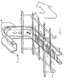
- the invention which is described comprises a plurality of substantially "L"-like shaped brackets M, which provide a first arm B1 which has to be fixed in a known way to the bearing structure, whereas a second arm B2 is apt to support and lock the raceway wherein the cables to be laid are made to pass. It is evident that the brackets M are placed transversely to the cable-bearing raceway, which rests on the second arm B2.
- said second arm B2 is equipped with means for hooking or engaging rapidly the raceway, which is preferably constituted by longitudinal longerons C and "U"-shaped cross hangers S.
- Said rapid engagement means are substantially constituted by one or more slots A parallel to the longitudinal axis of the arm B2 itself and opened upwards at one end thereof, wherein one or more of the longitudinal longerons C of the raceway are inserted at time of the laying.
- Said slots A are sized so as to allow, with a minimum sliding backlash, the passage of the longerons C of the raceway.
- the slots A are preferably opened at their end facing the free end of the second arm B2, but in any case they are all opened at one same end.
- One or more tangs or tongues L are thus created, which constitute the upper wall of each slot A and which, differently from what already known, are equipped, at an appropriate distance from the free end thereof, with a projection or jut 1 projecting towards the inside of the slot A apt to slightly reduce the clearance width of the passage for the longeron C, so that it is necessary to exert a slight forcing to bring the longeron C in abutment onto the bottom of the slot A, locking it in situ, by exploiting the proper elasticity of the material which is preferably, but not exclusively, metallic. Furthermore, the presence of such projection 1 also avoids any accidental disengagement of the raceway from the brackets M, it being however possible to perform the disassembly thereof by performing a manoeuvre contrary to the one described above, without the help of any tool.
- Said rapid engagement means allow thus to fix the wire trough or raceway to each bracket M by means of a unilateral release engagement system.
- the slots A and in particular the juts or projections 1 implementing the fixing for the metallic rods constituting the longerons C of the raceways, may have different shapes and the figure 3 and 4 show two of them.
- the first illustrated embodiment provides a jut 1 constituted by a rounded protuberance placed transversely to the slot A
- the second embodiment provides a jut constituted by a plane 1 inclined in the installation direction of the longerons C, which plane ends with a tooth opposing to the disengagement of the longeron C from the slot A.
- brackets apart from their "L” shape for the fixing thereof to the wall, can also be “C” or “U” shaped (as shown in figure 1), so as to allow the fixing thereof to the ceiling too.
Landscapes
- Engineering & Computer Science (AREA)
- Architecture (AREA)
- Civil Engineering (AREA)
- Structural Engineering (AREA)
- Details Of Indoor Wiring (AREA)
- Supports For Pipes And Cables (AREA)
- Laying Of Electric Cables Or Lines Outside (AREA)
- Clamps And Clips (AREA)
- Sheet Holders (AREA)
- Joining Of Building Structures In Genera (AREA)
Claims (8)
- Verbessertes Auslegersystem zur Befestigung von Kabelrinnen auf Tragauslegern, Ausleger (M) umfassend, wovon jeder einen Arm (B2) besitzt, der sich dazu eignet, die Kabelrinne zu tragen, wobei der Arm mit Einrichtungen ausgestattet ist, um Kabelrinnen schnell einzuhaken, welche Einrichtungen die Kabelrinnen automatisch festsetzen, ohne dass es notwendig wäre, auf irgendeine Weise auf die Ausleger (M) oder die Kabelrinne einzuwirken, wobei die Einrichtungen zum schnellen Einhaken von Kabelrinnen aus einem oder mehreren Schlitz/en (A) bestehen, der/die im Arm (B2) ausgebildet ist/sind und sich parallel zu dessen Längsachse erstreckt/erstrecken, wobei der eine oder die mehreren Schlitz/e an einem seiner/ihrer Enden nach oben offen ist/sind, wobei das andere Ende geschlossen ist, so dass ein oder mehrere Längsträger (C) der Kabelrinne zum Zeitpunkt ihrer Verlegung über ihre offenen Enden in die Schlitze (A) eingesteckt und zu den geschlossenen Enden hin geschoben werden kann/können,
dadurch gekennzeichnet, dass die obere Wand oder Seite jedes Schlitzes (A) eine Zunge (L) bildet, die in einem angemessenen Abstand von seinem freien Ende mit einem Vorsprung oder Überhang (1) ausgestattet ist, der zur Innenseite des Schlitzes (A) vorspringt und dazu ausgelegt ist, die lichte Breite des Durchgangs für den Längsträger (C) zu reduzieren, so dass eine leichte Druckwirkung ausgeübt werden muss, um den Längsträger (C) in Anlage am geschlossenen Ende des Schlitzes (A) zu bringen und ihn dort an Ort und Stelle festzusetzen, indem die Eigenelastizität des Materials ausgenutzt wird, aus dem der Ausleger (M) besteht. - Auslegersystem nach dem vorhergehenden Anspruch, dadurch gekennzeichnet, dass es mehrere im Wesentlichen "L"-, "U"- oder "C"-förmige Ausleger (M) umfasst, die einen ersten Arm (B1) bereitstellen, der dazu ausgelegt ist, auf eine bekannte Weise an der Halterungsstruktur befestigt zu werden, und einen zweiten Arm (B2), der den Trag- und Feststellarm darstellt; wobei die Ausleger (M) quer zur kabeltragenden Kabelrinne angeordnet sind, die auf dem zweiten Arm (B2) aufliegt.
- Auslegersystem nach jedem vorhergehenden Anspruch, dadurch gekennzeichnet, dass die Einrichtungen zum Einhaken und schnellen Festsetzen dazu ausgelegt sind, Kabelrinnen in der Form einer Gitterwanne zu sichern, die aus Längsträgern (C) und "U"-förmigen Querhängern (S) besteht.
- Auslegersystem nach jedem vorhergehenden Anspruch, dadurch gekennzeichnet, dass die Schlitze (A) so bemessen sind, dass der Durchgang der Längsträger (C) mit einem minimalen Gleitspiel ermöglicht wird.
- Auslegersystem nach jedem vorhergehenden Anspruch, dadurch gekennzeichnet, dass die Schlitze (A) an ihren dem freien Ende des zweiten Arms (B2) zugewandten Ende offen sind.
- Auslegersystem nach jedem vorhergehenden Anspruch, dadurch gekennzeichnet, dass die Ausleger (M) aus Metall hergestellt sind.
- Auslegersystem nach Anspruch 1, dadurch gekennzeichnet, dass der Überhang (1) aus einer abgerundeten Ausstülpung besteht, die quer zum Schlitz (A) angeordnet ist.
- Auslegersystem nach Anspruch 1, dadurch gekennzeichnet, dass der Überhang (1) aus einer Ebene besteht, die in der Einbaurichtung der Längsträger (C) geneigt ist, welche Ebene mit einem Zahn endet, der sich dem Freisetzen des Längsträgers (C) aus dem Schlitz (A) widersetzt.
Applications Claiming Priority (2)
| Application Number | Priority Date | Filing Date | Title |
|---|---|---|---|
| ITRM20020155 | 2002-10-01 | ||
| IT000155U ITRM20020155U1 (it) | 2002-10-01 | 2002-10-01 | Staffaggio perfezionato dotato di fissaggio ad innesto rapido per pass arelle a filo. |
Publications (2)
| Publication Number | Publication Date |
|---|---|
| EP1406362A1 EP1406362A1 (de) | 2004-04-07 |
| EP1406362B1 true EP1406362B1 (de) | 2005-10-19 |
Family
ID=31986046
Family Applications (1)
| Application Number | Title | Priority Date | Filing Date |
|---|---|---|---|
| EP03425347A Expired - Lifetime EP1406362B1 (de) | 2002-10-01 | 2003-05-30 | Verbesserte Trageeinrichtung für Drahtgitterkanal mit Schnellkupplung |
Country Status (5)
| Country | Link |
|---|---|
| EP (1) | EP1406362B1 (de) |
| AT (1) | ATE307410T1 (de) |
| DE (1) | DE60301931T2 (de) |
| ES (1) | ES2251673T3 (de) |
| IT (1) | ITRM20020155U1 (de) |
Cited By (1)
| Publication number | Priority date | Publication date | Assignee | Title |
|---|---|---|---|---|
| US11662041B2 (en) | 2019-07-29 | 2023-05-30 | Erico International Corporation | Support clip |
Families Citing this family (7)
| Publication number | Priority date | Publication date | Assignee | Title |
|---|---|---|---|---|
| FR2912003B1 (fr) | 2007-01-31 | 2009-04-17 | Icm Group | Dispositif de fixation pour chemin de cables en fils |
| AU2011202849B2 (en) * | 2007-01-31 | 2012-08-16 | I.C.M. Group | Attachment device for a yarn cable track |
| ES1067628Y (es) * | 2008-04-04 | 2008-09-01 | Schneider Electric Espana Sa | Perfil para soporte de bandejas de rejilla |
| DE102010055547B4 (de) | 2010-12-22 | 2019-07-11 | Legrand Gmbh | Kabeltragsystem umfassend eine Konsole und eine Gitterrinne |
| FR3008762B1 (fr) * | 2013-07-22 | 2015-07-24 | Legrand France | Console pour fournir un support horizontal a un objet tel qu'un chemin de cables |
| FR3029022B1 (fr) * | 2014-11-20 | 2016-12-23 | Niedax France | Support reversible pour chemin de cables |
| ES2827126A1 (es) * | 2019-11-19 | 2021-05-19 | Pemsa Cable Man S A | Soporte para bandejas portacables |
Citations (1)
| Publication number | Priority date | Publication date | Assignee | Title |
|---|---|---|---|---|
| FR2757696A1 (fr) * | 1996-12-19 | 1998-06-26 | Metal Deploye Sa | Console pour conduits porteurs |
Family Cites Families (1)
| Publication number | Priority date | Publication date | Assignee | Title |
|---|---|---|---|---|
| FR2726697B1 (fr) * | 1994-11-04 | 1997-01-17 | Petit Max | Profile de fixation pour chemin de cables avec ergots et butee d'encliquetage |
-
2002
- 2002-10-01 IT IT000155U patent/ITRM20020155U1/it unknown
-
2003
- 2003-05-30 ES ES03425347T patent/ES2251673T3/es not_active Expired - Lifetime
- 2003-05-30 DE DE60301931T patent/DE60301931T2/de not_active Expired - Lifetime
- 2003-05-30 AT AT03425347T patent/ATE307410T1/de active
- 2003-05-30 EP EP03425347A patent/EP1406362B1/de not_active Expired - Lifetime
Patent Citations (1)
| Publication number | Priority date | Publication date | Assignee | Title |
|---|---|---|---|---|
| FR2757696A1 (fr) * | 1996-12-19 | 1998-06-26 | Metal Deploye Sa | Console pour conduits porteurs |
Cited By (1)
| Publication number | Priority date | Publication date | Assignee | Title |
|---|---|---|---|---|
| US11662041B2 (en) | 2019-07-29 | 2023-05-30 | Erico International Corporation | Support clip |
Also Published As
| Publication number | Publication date |
|---|---|
| DE60301931T2 (de) | 2006-07-20 |
| ES2251673T3 (es) | 2006-05-01 |
| ITRM20020155U1 (it) | 2004-04-02 |
| ATE307410T1 (de) | 2005-11-15 |
| DE60301931D1 (de) | 2005-11-24 |
| EP1406362A1 (de) | 2004-04-07 |
Similar Documents
| Publication | Publication Date | Title |
|---|---|---|
| US6491270B1 (en) | Bar hanger and mounting clip assembly | |
| US6590154B1 (en) | Accessory for fixing a wire cable tray, and wire cable tray equipped with at least such an accessory | |
| US7468491B2 (en) | Accessory for lifting and bonding wire cable trays | |
| EP2254211B1 (de) | Teleskopdrahtkabel-Auflagesystem | |
| US6431501B1 (en) | Interlocking modular ladder-type cable tray | |
| US5009383A (en) | Suspended ceiling electrical bracket | |
| US6401939B1 (en) | Wire cable rack equipped with at least one fixing accessory, and corresponding fixing accessory | |
| US7903924B2 (en) | Connector for splicing and hanging cable trays | |
| AU2017369798B2 (en) | Suspension assembly | |
| JP2601915B2 (ja) | ケーブル敷設通路 | |
| US8157235B2 (en) | Device for fixing a wire cable raceway to a threaded rod | |
| AU2020347547B2 (en) | Suspension assembly | |
| US7708491B2 (en) | Splice bar for connecting cable tray sections | |
| US7523897B2 (en) | Device for fixing a wire on a load bearing element provided with at least one opening | |
| EP1406362B1 (de) | Verbesserte Trageeinrichtung für Drahtgitterkanal mit Schnellkupplung | |
| JP2002233024A (ja) | 長尺ビルディングサービス供給手段の支持手段 | |
| US20040104322A1 (en) | Support bracket for element for forming a cable tray | |
| US8177172B2 (en) | Wire-type cable raceway, especially a cable raceway for home use | |
| US20230291192A1 (en) | Holding assembly | |
| RU187594U1 (ru) | Кабельный лоток с системой встроенного соединителя секций | |
| US7387287B2 (en) | Perforated section supporting device adapted to be fixed to a surface such as a ceiling | |
| US12580370B2 (en) | Cable tray exit | |
| US12188588B2 (en) | Securing bracket | |
| NL2035358B1 (en) | Solar panel installation system | |
| CN116529445A (zh) | 补强设备 |
Legal Events
| Date | Code | Title | Description |
|---|---|---|---|
| PUAI | Public reference made under article 153(3) epc to a published international application that has entered the european phase |
Free format text: ORIGINAL CODE: 0009012 |
|
| AK | Designated contracting states |
Kind code of ref document: A1 Designated state(s): AT BE BG CH CY CZ DE DK EE ES FI FR GB GR HU IE IT LI LU MC NL PT RO SE SI SK TR |
|
| AX | Request for extension of the european patent |
Extension state: AL LT LV MK |
|
| 17P | Request for examination filed |
Effective date: 20040629 |
|
| 17Q | First examination report despatched |
Effective date: 20040928 |
|
| AKX | Designation fees paid |
Designated state(s): AT BE BG CH CY CZ DE DK EE ES FI FR GB GR HU IE IT LI LU MC NL PT RO SE SI SK TR |
|
| AXX | Extension fees paid |
Extension state: AL Payment date: 20040629 Extension state: LT Payment date: 20040629 Extension state: MK Payment date: 20040629 Extension state: LV Payment date: 20040629 |
|
| GRAP | Despatch of communication of intention to grant a patent |
Free format text: ORIGINAL CODE: EPIDOSNIGR1 |
|
| GRAS | Grant fee paid |
Free format text: ORIGINAL CODE: EPIDOSNIGR3 |
|
| GRAA | (expected) grant |
Free format text: ORIGINAL CODE: 0009210 |
|
| AK | Designated contracting states |
Kind code of ref document: B1 Designated state(s): AT BE BG CH CY CZ DE DK EE ES FI FR GB GR HU IE IT LI LU MC NL PT RO SE SI SK TR |
|
| AX | Request for extension of the european patent |
Extension state: AL LT LV MK |
|
| PG25 | Lapsed in a contracting state [announced via postgrant information from national office to epo] |
Ref country code: FI Free format text: LAPSE BECAUSE OF FAILURE TO SUBMIT A TRANSLATION OF THE DESCRIPTION OR TO PAY THE FEE WITHIN THE PRESCRIBED TIME-LIMIT Effective date: 20051019 Ref country code: SK Free format text: LAPSE BECAUSE OF FAILURE TO SUBMIT A TRANSLATION OF THE DESCRIPTION OR TO PAY THE FEE WITHIN THE PRESCRIBED TIME-LIMIT Effective date: 20051019 Ref country code: CH Free format text: LAPSE BECAUSE OF FAILURE TO SUBMIT A TRANSLATION OF THE DESCRIPTION OR TO PAY THE FEE WITHIN THE PRESCRIBED TIME-LIMIT Effective date: 20051019 Ref country code: CZ Free format text: LAPSE BECAUSE OF FAILURE TO SUBMIT A TRANSLATION OF THE DESCRIPTION OR TO PAY THE FEE WITHIN THE PRESCRIBED TIME-LIMIT Effective date: 20051019 Ref country code: LI Free format text: LAPSE BECAUSE OF FAILURE TO SUBMIT A TRANSLATION OF THE DESCRIPTION OR TO PAY THE FEE WITHIN THE PRESCRIBED TIME-LIMIT Effective date: 20051019 Ref country code: RO Free format text: LAPSE BECAUSE OF FAILURE TO SUBMIT A TRANSLATION OF THE DESCRIPTION OR TO PAY THE FEE WITHIN THE PRESCRIBED TIME-LIMIT Effective date: 20051019 Ref country code: NL Free format text: LAPSE BECAUSE OF FAILURE TO SUBMIT A TRANSLATION OF THE DESCRIPTION OR TO PAY THE FEE WITHIN THE PRESCRIBED TIME-LIMIT Effective date: 20051019 Ref country code: SI Free format text: LAPSE BECAUSE OF FAILURE TO SUBMIT A TRANSLATION OF THE DESCRIPTION OR TO PAY THE FEE WITHIN THE PRESCRIBED TIME-LIMIT Effective date: 20051019 |
|
| REG | Reference to a national code |
Ref country code: GB Ref legal event code: FG4D |
|
| REG | Reference to a national code |
Ref country code: CH Ref legal event code: EP |
|
| REG | Reference to a national code |
Ref country code: IE Ref legal event code: FG4D |
|
| REF | Corresponds to: |
Ref document number: 60301931 Country of ref document: DE Date of ref document: 20051124 Kind code of ref document: P |
|
| PG25 | Lapsed in a contracting state [announced via postgrant information from national office to epo] |
Ref country code: SE Free format text: LAPSE BECAUSE OF FAILURE TO SUBMIT A TRANSLATION OF THE DESCRIPTION OR TO PAY THE FEE WITHIN THE PRESCRIBED TIME-LIMIT Effective date: 20060119 Ref country code: BG Free format text: LAPSE BECAUSE OF FAILURE TO SUBMIT A TRANSLATION OF THE DESCRIPTION OR TO PAY THE FEE WITHIN THE PRESCRIBED TIME-LIMIT Effective date: 20060119 Ref country code: DK Free format text: LAPSE BECAUSE OF FAILURE TO SUBMIT A TRANSLATION OF THE DESCRIPTION OR TO PAY THE FEE WITHIN THE PRESCRIBED TIME-LIMIT Effective date: 20060119 Ref country code: GR Free format text: LAPSE BECAUSE OF FAILURE TO SUBMIT A TRANSLATION OF THE DESCRIPTION OR TO PAY THE FEE WITHIN THE PRESCRIBED TIME-LIMIT Effective date: 20060119 |
|
| PG25 | Lapsed in a contracting state [announced via postgrant information from national office to epo] |
Ref country code: PT Free format text: LAPSE BECAUSE OF FAILURE TO SUBMIT A TRANSLATION OF THE DESCRIPTION OR TO PAY THE FEE WITHIN THE PRESCRIBED TIME-LIMIT Effective date: 20060320 |
|
| LTIE | Lt: invalidation of european patent or patent extension |
Effective date: 20051019 |
|
| NLV1 | Nl: lapsed or annulled due to failure to fulfill the requirements of art. 29p and 29m of the patents act | ||
| PG25 | Lapsed in a contracting state [announced via postgrant information from national office to epo] |
Ref country code: HU Free format text: LAPSE BECAUSE OF FAILURE TO SUBMIT A TRANSLATION OF THE DESCRIPTION OR TO PAY THE FEE WITHIN THE PRESCRIBED TIME-LIMIT Effective date: 20060420 |
|
| REG | Reference to a national code |
Ref country code: CH Ref legal event code: PL |
|
| REG | Reference to a national code |
Ref country code: ES Ref legal event code: FG2A Ref document number: 2251673 Country of ref document: ES Kind code of ref document: T3 |
|
| PG25 | Lapsed in a contracting state [announced via postgrant information from national office to epo] |
Ref country code: IE Free format text: LAPSE BECAUSE OF NON-PAYMENT OF DUE FEES Effective date: 20060530 |
|
| PG25 | Lapsed in a contracting state [announced via postgrant information from national office to epo] |
Ref country code: MC Free format text: LAPSE BECAUSE OF NON-PAYMENT OF DUE FEES Effective date: 20060531 |
|
| ET | Fr: translation filed | ||
| PLBE | No opposition filed within time limit |
Free format text: ORIGINAL CODE: 0009261 |
|
| STAA | Information on the status of an ep patent application or granted ep patent |
Free format text: STATUS: NO OPPOSITION FILED WITHIN TIME LIMIT |
|
| 26N | No opposition filed |
Effective date: 20060720 |
|
| REG | Reference to a national code |
Ref country code: IE Ref legal event code: MM4A |
|
| GBPC | Gb: european patent ceased through non-payment of renewal fee |
Effective date: 20070530 |
|
| PG25 | Lapsed in a contracting state [announced via postgrant information from national office to epo] |
Ref country code: GB Free format text: LAPSE BECAUSE OF NON-PAYMENT OF DUE FEES Effective date: 20070530 |
|
| PG25 | Lapsed in a contracting state [announced via postgrant information from national office to epo] |
Ref country code: EE Free format text: LAPSE BECAUSE OF FAILURE TO SUBMIT A TRANSLATION OF THE DESCRIPTION OR TO PAY THE FEE WITHIN THE PRESCRIBED TIME-LIMIT Effective date: 20051019 |
|
| PG25 | Lapsed in a contracting state [announced via postgrant information from national office to epo] |
Ref country code: LU Free format text: LAPSE BECAUSE OF NON-PAYMENT OF DUE FEES Effective date: 20060530 Ref country code: TR Free format text: LAPSE BECAUSE OF FAILURE TO SUBMIT A TRANSLATION OF THE DESCRIPTION OR TO PAY THE FEE WITHIN THE PRESCRIBED TIME-LIMIT Effective date: 20051019 |
|
| PG25 | Lapsed in a contracting state [announced via postgrant information from national office to epo] |
Ref country code: CY Free format text: LAPSE BECAUSE OF FAILURE TO SUBMIT A TRANSLATION OF THE DESCRIPTION OR TO PAY THE FEE WITHIN THE PRESCRIBED TIME-LIMIT Effective date: 20051019 |
|
| BECA | Be: change of holder's address |
Owner name: BOCCHIOTTI S.P.A. SOCIETA PER L'INDUSTRIA ELETTROT Effective date: 20091216 |
|
| BECH | Be: change of holder |
Owner name: BOCCHIOTTI S.P.A. SOCIETA PER L'INDUSTRIA ELETTROT Effective date: 20091216 |
|
| REG | Reference to a national code |
Ref country code: FR Ref legal event code: TP Ref country code: FR Ref legal event code: CA |
|
| REG | Reference to a national code |
Ref country code: ES Ref legal event code: PC2A |
|
| REG | Reference to a national code |
Ref country code: FR Ref legal event code: RM |
|
| REG | Reference to a national code |
Ref country code: FR Ref legal event code: PLFP Year of fee payment: 13 |
|
| REG | Reference to a national code |
Ref country code: FR Ref legal event code: CA Effective date: 20160217 |
|
| REG | Reference to a national code |
Ref country code: FR Ref legal event code: PLFP Year of fee payment: 14 |
|
| REG | Reference to a national code |
Ref country code: FR Ref legal event code: PLFP Year of fee payment: 15 |
|
| REG | Reference to a national code |
Ref country code: FR Ref legal event code: PLFP Year of fee payment: 16 |
|
| PGFP | Annual fee paid to national office [announced via postgrant information from national office to epo] |
Ref country code: IT Payment date: 20220506 Year of fee payment: 20 Ref country code: FR Payment date: 20220530 Year of fee payment: 20 Ref country code: ES Payment date: 20220601 Year of fee payment: 20 Ref country code: DE Payment date: 20220519 Year of fee payment: 20 |
|
| PGFP | Annual fee paid to national office [announced via postgrant information from national office to epo] |
Ref country code: BE Payment date: 20220519 Year of fee payment: 20 Ref country code: AT Payment date: 20220523 Year of fee payment: 20 |
|
| REG | Reference to a national code |
Ref country code: DE Ref legal event code: R071 Ref document number: 60301931 Country of ref document: DE |
|
| REG | Reference to a national code |
Ref country code: BE Ref legal event code: MK Effective date: 20230530 Ref country code: ES Ref legal event code: FD2A Effective date: 20230606 |
|
| REG | Reference to a national code |
Ref country code: AT Ref legal event code: MK07 Ref document number: 307410 Country of ref document: AT Kind code of ref document: T Effective date: 20230530 |
|
| PG25 | Lapsed in a contracting state [announced via postgrant information from national office to epo] |
Ref country code: ES Free format text: LAPSE BECAUSE OF EXPIRATION OF PROTECTION Effective date: 20230531 |