EP1407111B1 - Systeme conducteur electrique - Google Patents
Systeme conducteur electrique Download PDFInfo
- Publication number
- EP1407111B1 EP1407111B1 EP02751296A EP02751296A EP1407111B1 EP 1407111 B1 EP1407111 B1 EP 1407111B1 EP 02751296 A EP02751296 A EP 02751296A EP 02751296 A EP02751296 A EP 02751296A EP 1407111 B1 EP1407111 B1 EP 1407111B1
- Authority
- EP
- European Patent Office
- Prior art keywords
- drill pipe
- pipe section
- conductive
- conductor
- female
- Prior art date
- Legal status (The legal status is an assumption and is not a legal conclusion. Google has not performed a legal analysis and makes no representation as to the accuracy of the status listed.)
- Expired - Lifetime
Links
- 239000004020 conductor Substances 0.000 claims abstract description 71
- 238000007789 sealing Methods 0.000 claims abstract description 25
- 239000002184 metal Substances 0.000 description 18
- 239000004519 grease Substances 0.000 description 16
- 239000012530 fluid Substances 0.000 description 13
- 238000000034 method Methods 0.000 description 6
- 239000012212 insulator Substances 0.000 description 5
- 238000005259 measurement Methods 0.000 description 5
- 229920001971 elastomer Polymers 0.000 description 4
- 239000000806 elastomer Substances 0.000 description 4
- 239000011810 insulating material Substances 0.000 description 4
- 230000013011 mating Effects 0.000 description 4
- 230000008569 process Effects 0.000 description 4
- 238000006073 displacement reaction Methods 0.000 description 3
- 230000007613 environmental effect Effects 0.000 description 3
- 238000001125 extrusion Methods 0.000 description 3
- 238000005304 joining Methods 0.000 description 3
- 230000008901 benefit Effects 0.000 description 2
- 238000005520 cutting process Methods 0.000 description 2
- 230000003247 decreasing effect Effects 0.000 description 2
- 230000001050 lubricating effect Effects 0.000 description 2
- 238000005461 lubrication Methods 0.000 description 2
- 238000004519 manufacturing process Methods 0.000 description 2
- 239000000463 material Substances 0.000 description 2
- 230000035515 penetration Effects 0.000 description 2
- 238000003825 pressing Methods 0.000 description 2
- 230000008439 repair process Effects 0.000 description 2
- 239000012858 resilient material Substances 0.000 description 2
- 230000000717 retained effect Effects 0.000 description 2
- 229910000831 Steel Inorganic materials 0.000 description 1
- 230000004308 accommodation Effects 0.000 description 1
- 230000003190 augmentative effect Effects 0.000 description 1
- 230000005540 biological transmission Effects 0.000 description 1
- 239000000919 ceramic Substances 0.000 description 1
- 238000004140 cleaning Methods 0.000 description 1
- 230000000295 complement effect Effects 0.000 description 1
- 150000001875 compounds Chemical class 0.000 description 1
- 238000005553 drilling Methods 0.000 description 1
- 238000011065 in-situ storage Methods 0.000 description 1
- 230000007246 mechanism Effects 0.000 description 1
- 230000004044 response Effects 0.000 description 1
- 125000006850 spacer group Chemical group 0.000 description 1
- 239000010959 steel Substances 0.000 description 1
- 238000013022 venting Methods 0.000 description 1
Images


Classifications
-
- E—FIXED CONSTRUCTIONS
- E21—EARTH OR ROCK DRILLING; MINING
- E21B—EARTH OR ROCK DRILLING; OBTAINING OIL, GAS, WATER, SOLUBLE OR MELTABLE MATERIALS OR A SLURRY OF MINERALS FROM WELLS
- E21B17/00—Drilling rods or pipes; Flexible drill strings; Kellies; Drill collars; Sucker rods; Cables; Casings; Tubings
- E21B17/02—Couplings; joints
- E21B17/028—Electrical or electro-magnetic connections
- E21B17/0285—Electrical or electro-magnetic connections characterised by electrically insulating elements
Definitions
- the present invention relates to the transmission of power and data within a well bore, in particular, through a drillstring.
- each drill pipe section includes one or more conductors, each conductor having a contact at each end of the section.
- the contacts of adjacent drill pipe sections abut and a circuit is formed over the drill string.
- the object of the present invention is to provide an apparatus and method for conveniently and reliably disposing cabling in a drill string.
- a generally tubular drill pipe having a conductive path over a plurality of drill pipe sections, each drill pipe section having a first end and a second end, and having a wall, and the first end having a first radial sealing surfaces and the second end having a corresponding second radial sealing surfaces, such that when the first or second end of one drill pipe section is engaged with the second or first end respectively of another drill pipe section, at least one seal is formed, wherein a conductor is connected to a first contact means at one end and a plug at the other end, and, wherein ingress protection means are provided to protect the contact means from ingress from inside or outside of the drill pipe section.
- a drill pipe section is generally tubular and therefore has a central throughbore often used for the passage of well fluids.
- the present invention may also include bores formed or situated in the walls of drill pipe sections; and reference to bores refers to these wall bores, whereas the main bore of the drill pipe is identified as the central throughbore.
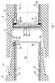
- FIG. 1 shows opposing ends of two adjacent drill pipe sections 10,12.
- One drill pipe 12 has a female receiving thread 16, which is engaged by rotation of the corresponding male thread 14 of the other drill pipe 10.
- Each drill pipe has three bores drilled longitudinally inside the drill pipe wall, equally spaced around the radius of the drillpipe section (when spaced at 120° around the radius of the drill pipe, a longitudinal section taken centrally through the drill pipe section would not show two bores; two bores 20, 22 are here shown to better illustrate the nature of the connections).
- the bore 20 opens at the male end at a region 25 forward of (considering forward to be towards the right in the figure) and proximal to the thread 14.
- a conductor 21 is introduced into this bore 20. Space or other considerations within the drill pipe, and its wall cavity, wall may require the conductor 21 to have an aspect ration not equal to one.
- aspect ratio is the measurement of the overall length of the conductor divided by the measurement of the overall width of the conductor.
- a conductor 21 with a circular cross-sectional area would have equal length and width measurements, and thus would have an aspect ration equal to one.
- a conductor 21 that is rectangular in cross-sectional area would have a length measurement greater than a width measurement, consequently this conductor would have an aspect ratio greater than one.
- a male connector 30 is attached, the conductor 21 terminating in this male connector. If necessary, a recess is provided to accept the male connector 30.
- the male connector is annular, and includes three annular conductive rings 35, 36, 37 having surfaces exposed on the outer circumference of the male connector. Each of the three conductive rings are connected respectively to one of the three conductors. A metal sealing ring 38 is also included in the male connector.
- the drill pipe 12 also features three longitudinal bores (40, 42 being visible here) which emerge at the female end of the drill pipe forward of (again considering forward to be towards the right in the figure) and proximal to the thread 16.
- the bores 40, 42 include conductors 41, 43.
- a female connector 50 is attached, the conductor terminating in this female connector.
- a recess 51 is provided to accept the female connector 50.
- the female connector is annular, and includes three annular conductive rings 56, 57, 58 having surfaces exposed on its inner circumference. Each of the three conductive rings are connected respectively to one of the three conductors.
- the female connector includes a radial shoulder 53, this shoulder having a metal sealing surface 54. Incorporated in the radial shoulder is an annular seal 59, such as an elastomeric seal.
- the metal sealing ring 38 of the male connector compresses the annular seal 59 of the female connector until the metal sealing ring 38 abuts the female connector's metal sealing surface 53, sealing the conductive rings from inner wellbore fluid
- the annual seal is elastomeric in nature.
- the components of the female connector 50 lie substantially flush with the inner surface of the drill pipe section's central throughbore 70.
- the three conductive rings 35, 36, 37 of the male connector now lie in conjunction with the three conductive rings 56, 57, 58 of the female connector.
- These connections are sealed on the one hand by the metal to metal seal between the male connector's sealing ring 38 and female connector metal sealing surface 53, augmented by the annular seal 59 which is energised by the metal sealing ring 38, and on the other hand by the mating threads 14, 16 of the male and female ends of the adjacent drill pipe sections.
- An o-ring seal 11 is included in the shoulder 13 of the male end of the drill pipe section 10.
- Each drill pipe section includes both a male end and a female end having respectively male connector and female connector as described, the conductors disposed in the bores running the entire length of each drill pipe section. As these drill pipe sections are made up into a drill string, three conductive paths along the drill string are formed.
- the drill pipe section's longitudinal bores 20, 22, 40, 42 ideally run parallel to the drill pipe sections' axes.
- the mating threads 14, 16 may not engage to the same position as when they were initially made up.
- the drill pipe sections' ends may be shortened and/or rethreaded.
- the male and female connectors 30, 50 will therefore have to be repositioned, and accommodating recesses/profiles in the drill pipe sections have to be remilled.
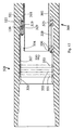
- the central throughbore of a drill pipe section typically includes a widened middle region 72 between to relatively narrow end regions 73, 74, the end regions having a greater thickness of material to give additional strength in the area where the drill pipes are joined. It may not therefore be possible to produce a straight longitudinal bore along the entire length of the drill pipe section without impinging upon the drill pipe section's threads.
- two aligned bores 80, 81 are drilled into the drill pipe section, and a tube of resilient material 85 is attached in a sealed manner between the facing mouths 83, 84 of the two bores to form an enclosed bore running the length of the drill pipe section.
- the drill pipe section's bores are filled with oil. As the environmental pressure in the vell bore hole is increased, this oil may be pressurised in order to equalise the pressure between the connection with the external pressure and so reduce the stress exerted on the seals.
- the resilient material 85 connected between the facing mouths 83, 84 is compressed in response to increasing external pressure, reducing the volume of the bore 80, 81, increasing the bore's pressure and thus reducing the pressure difference.
- the equalisation of the bore's pressure could be alternatively or additionally be achieved using, for example, a pressure gauge and actuator mechanism
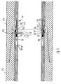
- the male connector 91 installed in a drill pipe section 110 includes two forward facing collars 91, 92.
- annular cavity if formed between the two forward facing collars 91, 92 of the male connector 30.
- annular seal 95 biased by a spring 96 to be held covering the surface of the conductive rings 36, 37, 38.
- the inner collar 92 extends further from the male connector than the outer collar 91.
- the outer collar includes a ledge 98 which, in conjunction with the drill pipe, forms a circular groove 99.
- the adjacent drill pipe section 120 is similar to the drill pipe section 110 just described, and includes three longitudinal bores 140, 142 (only two of which are visible here) located near the inner surface of the drill pipe section.
- the bores rather than being integrally formed in the wall of the drill pipe section, are provided in a lining, or inner sleeve.
- the conductors are here formed between two coaxial tubes, the conductors being semi-cylindrical elements of similar curvature to the tubes, such that the three conductors can be placed axially upon the inner tube, with spacer means between each conductor, each conductor subtending some angle less than 120° of the tube's circumference.
- the outer tube is then affixed to the inner tube, and the assemble is then secured in the drill pipe section.
- the conductor assembly may be formed in part by an extrusion process, the inner tube being formed using a gas impermeable metal tube, or sleeve, 223 the outer surface of which is coated by extrudate 224, the conductors 120 being affixed to the coated inner tube, and the inner tube and conductors 120 being coated again in another extrusion stage 225 to cover and hold the conductors 120 in a spaced relationship.
- This assembly may now be introduced to the drill pipe section 110.
- the inner sleeve shields the conductors from wellbore fluid.
- the three semi-cylindrical conductors 120 are each respectively connected to one of the three conductive rings 36, 37, 38 present in the female connector described below.
- a portion of the inner surface of the drill pipe at the female end is removed to create a profile 103.
- the lining may be made up of layers 104, 105, 106 to form the profile; it will be noted that the profile of the male end of the inner surface is the complement of the profile of the female end of the inner surface, so the profile may be achieved by using similar layers of material, with the different layers being axially displaced to create the profile.
- This profile 103 engages with a female end connector 100. When one side of the drill string is considered in section as shown here, a recess is milled into the drill pipe.
- the female end connector includes, considering a half section portion, two forward facing collars 134, 135, one of which, the outer collar 134, abuts an inner portion 133 of the drillpipe section 120, and one of which, the inner collar 135, both engages with the recess in the profile 103 and features a shoulder 137 abuts the inner portion of the drill pipe section.
- the female connector includes three bores 150, 152 similar to those 140, 142 in the drill pipe section 120, these bores being less radially displaced. Conductors run through the bores of the female connector, each conductor being connected via a contact element 151, 153 to the corresponding conductor of drill pipe section.
- the female connector also includes two backward facing collars 131, 132.
- Three axially spaced conductive rings 171, 172, 173 are situated on the outer surface of the cylinder formed by the inner collar 132.
- the three conductors of the female connector are each respectively connected to one of the three rings.
- An annular cavity 136 is formed between the two backward facing collars 131, 132 of the female connector.
- an annular seal 160 biased by a spring 161 to be held covering the surface of the conductive rings.
- the inner collar 132 includes a shoulder 163 on its inner diameter.
- the annular seal 160 and its spring 161 are displaced deeper into the cavity. As it is displaced, the seal 160 wipes the surface of the conductive rings 171, 172, 173, ensuring that a good contact will be formed. Simultaneously, the outer collar 131 of the female connector displaces the male connector's annular seal 95, wiping the male connector's conductive rings 36, 37, 38. When the male and female connector's are fully engaged, the three conductive rings 36, 37, 38 of the male connector and the three conductive rings 171, 172, 173 of the female connector slide into conjunction so as to form three conductive paths from the drill pipe 110 to the adjacent drill pipe 120.
- Each drill pipe section thus features a male connector and female connector as described, so that a three conductive circuits down the length of the drill pipe are produced.
- the bores are oil filled in order that they may be balanced with the external pressure.
- This pressure is set such that it does not stress the seals when the environmental pressure is low, but is sufficient to afford protection to the seals when the environmental pressure is high.
- a weep hole may instead be provided. It will be realised that position of the pressure release valve may be varied, for example it could be included at the female end of drill pipe section 12 backward of the female thread, venting excess lubricating grease outside the drill string.
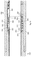
- three conductors 21 are longitudinally disposed in a laminate tubular member 108.
- the tubular member may be formed partly by extrusion, for example using a steel tube 223 having an insulating layer 224, the conductors 21 then being set with another insulating layer 225.
- the tubular member is then inserted in the drill pipe section 110.
- the tubular member may be formed to follow the inner surface of the drill pipe section, for example being swaged to follow the widened portion commonly present in the mid-section of drill pipe sections.
- the drill pipe section's longitudinal bores 20, 22, 40, 42 ideally run essentially parallel to the drill pipe sections' axes.
- the mating threads 14, 16 may not engage to the same position as when they were initially made up.
- the drill pipe sections' ends may be shortened and/or rethreaded.
- the male and female connectors 30, 50 will therefore have to be repositioned, and accommodating recesses/profiles in the drill pipe sections have to be re-milled.
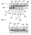
- the conductive rings 311, 312, 313 of the male threaded end are brought into contact with the conductive rings 331, 332, 333 of the female thread end module 330, the garter springs of the male threaded end pressing against the female thread end module's conductive rings 331, 332, 333 to ensure a good electrical contact is made.
- the liner tubes 302 of the two drill pipe sections meet to form a continuous throughbore, although they need not.
Landscapes
- Engineering & Computer Science (AREA)
- Life Sciences & Earth Sciences (AREA)
- Geology (AREA)
- Mining & Mineral Resources (AREA)
- Mechanical Engineering (AREA)
- Physics & Mathematics (AREA)
- Environmental & Geological Engineering (AREA)
- Fluid Mechanics (AREA)
- General Life Sciences & Earth Sciences (AREA)
- Geochemistry & Mineralogy (AREA)
- Earth Drilling (AREA)
- Forklifts And Lifting Vehicles (AREA)
- Lifting Devices For Agricultural Implements (AREA)
- Drilling And Boring (AREA)
- Laying Of Electric Cables Or Lines Outside (AREA)
- Connector Housings Or Holding Contact Members (AREA)
- Drilling Tools (AREA)
- Superconductors And Manufacturing Methods Therefor (AREA)
- Pressure Welding/Diffusion-Bonding (AREA)
- Iron Core Of Rotating Electric Machines (AREA)
- Selective Calling Equipment (AREA)
- Steering Control In Accordance With Driving Conditions (AREA)
- Control Of Eletrric Generators (AREA)
Claims (8)
- Tige de forage généralement tubulaire ayant un chemin conducteur sur une pluralité de sections de tiges de forage (300), chaque section de tige de forage ayant une première extrémité (310) et une deuxième extrémité (320), et ayant une paroi, et la première extrémité ayant une première surface d'étanchéité radiale (304) et la deuxième extrémité ayant une deuxième surface d'étanchéité radiale correspondante (334), de telle manière que quand la première extrémité ou la deuxième extrémité d'une section de tige de forage est engagée avec la deuxième extrémité ou la première extrémité respectivement d'une autre section de tige de forage, au moins un joint d'étanchéité est formé, et ayant un conducteur connecté sur un premier moyen de contact (311) au niveau de sa première extrémité caractérisée en ce que le conducteur est connecté sur une fiche (319) au niveau de sa deuxième extrémité, et, dans laquelle des moyens de protection contre toute entrée (302) sont mis en oeuvre pour protéger le moyen de contact contre toute entrée en provenance de l'intérieur ou de l'extérieur de la section de tige de forage.
- Tige de forage selon la revendication 1, dans laquelle la fiche se connecte sur un module par le biais d'une prise électrique (329).
- Tige de forage selon la revendication 2, dans laquelle le module contient un deuxième moyen de contact (331).
- Tige de forage selon la revendication 3, dans laquelle le premier moyen de contact et le deuxième moyen de contact sont mis en oeuvre par des anneaux conducteurs correspondants se situant de manière coaxiale par rapport à la tige de forage.
- Tige de forage selon la revendication 4, dans laquelle la paroi comprend à l'intérieur de celle-ci au moins un alésage, l'alésage ayant un conducteur disposé à l'intérieur de celui-ci, et ce conducteur étant connecté sur un premier anneau conducteur au niveau de la première extrémité, et une fiche au niveau de la deuxième extrémité, dans laquelle la fiche est en mesure de recevoir un module contenant à l'intérieur de celui-ci un nombre égal d'anneaux conducteurs, de telle manière que quand la première extrémité ou la deuxième extrémité d'une section de tige de forage est engagée avec la deuxième extrémité ou la première extrémité respectivement d'une autre section de tige de forage, les connexions conductrices sont formées dans le volume étanche afin de mettre en oeuvre des chemins conducteurs sur la pluralité de sections de tiges de forage.
- Train de tiges de forage selon la revendication 4, dans lequel les trois premiers anneaux conducteurs sont espacés de manière axiale, et les trois deuxièmes anneaux conducteurs sont espacés de manière axiale.
- Train de tiges de forage selon la revendication 6, dans lequel les trois premiers anneaux conducteurs sont munis d'encoches afin de recevoir un conducteur annulaire extérieur, de telle manière que les connexions conductrices sont constituées des trois premiers anneaux conducteurs en contact avec le conducteur annulaire extérieur.
- Train de tiges de forage selon la revendication 7, dans lequel le conducteur annulaire extérieur comporte un ressort annulaire (341).
Applications Claiming Priority (3)
| Application Number | Priority Date | Filing Date | Title |
|---|---|---|---|
| GB0115524 | 2001-06-26 | ||
| GBGB0115524.1A GB0115524D0 (en) | 2001-06-26 | 2001-06-26 | Conducting system |
| PCT/GB2002/002933 WO2003001023A1 (fr) | 2001-06-26 | 2002-06-26 | Systeme conducteur electrique |
Publications (2)
| Publication Number | Publication Date |
|---|---|
| EP1407111A1 EP1407111A1 (fr) | 2004-04-14 |
| EP1407111B1 true EP1407111B1 (fr) | 2007-03-21 |
Family
ID=9917324
Family Applications (1)
| Application Number | Title | Priority Date | Filing Date |
|---|---|---|---|
| EP02751296A Expired - Lifetime EP1407111B1 (fr) | 2001-06-26 | 2002-06-26 | Systeme conducteur electrique |
Country Status (9)
| Country | Link |
|---|---|
| US (1) | US7114970B2 (fr) |
| EP (1) | EP1407111B1 (fr) |
| AT (1) | ATE357578T1 (fr) |
| AU (1) | AU2002349873B2 (fr) |
| CA (1) | CA2451358C (fr) |
| DE (1) | DE60219017D1 (fr) |
| GB (1) | GB0115524D0 (fr) |
| NO (1) | NO329260B1 (fr) |
| WO (1) | WO2003001023A1 (fr) |
Families Citing this family (58)
| Publication number | Priority date | Publication date | Assignee | Title |
|---|---|---|---|---|
| US20070056155A1 (en) * | 2002-09-13 | 2007-03-15 | Reimert Larry E | Method of installing flange on tubular body at desired elevation |
| US20060033638A1 (en) * | 2004-08-10 | 2006-02-16 | Hall David R | Apparatus for Responding to an Anomalous Change in Downhole Pressure |
| FR2881172B1 (fr) * | 2005-01-25 | 2008-03-14 | Deviatec Sarl | Tige tubulaire de forage |
| US7277026B2 (en) * | 2005-05-21 | 2007-10-02 | Hall David R | Downhole component with multiple transmission elements |
| US7291028B2 (en) * | 2005-07-05 | 2007-11-06 | Hall David R | Actuated electric connection |
| US7649475B2 (en) * | 2007-01-09 | 2010-01-19 | Hall David R | Tool string direct electrical connection |
| US7605715B2 (en) | 2006-07-10 | 2009-10-20 | Schlumberger Technology Corporation | Electromagnetic wellbore telemetry system for tubular strings |
| AU2011253677B2 (en) * | 2006-08-23 | 2012-01-12 | Baker Hughes Incorporated | Annular electrical wet connect |
| GB2477052B (en) * | 2006-08-23 | 2011-09-28 | Baker Hughes Inc | Annular electrical wet connector |
| US7644755B2 (en) * | 2006-08-23 | 2010-01-12 | Baker Hughes Incorporated | Annular electrical wet connect |
| CA2572755A1 (fr) * | 2007-01-03 | 2008-07-03 | Ken Shipalesky | Systeme de raccordement electrique par cable metallique |
| CA2677346C (fr) * | 2007-02-05 | 2014-03-18 | Quick Connectors Inc. | Connecteur electrique de fond pour lutter contre une decompression rapide |
| CA2687737A1 (fr) * | 2007-06-08 | 2008-12-18 | Schlumberger Canada Limited | Repetiteur pour tige de forage cablee |
| US20090038849A1 (en) * | 2007-08-07 | 2009-02-12 | Schlumberger Technology Corporation | Communication Connections for Wired Drill Pipe Joints |
| US7806191B2 (en) * | 2007-12-27 | 2010-10-05 | Intelliserv, Llc | Communication connections for wired drill pipe joints for providing multiple communication paths |
| US8322440B2 (en) * | 2008-03-06 | 2012-12-04 | Vetco Gray Inc. | Integrated electrical connector for use in a wellhead tree |
| WO2009133474A2 (fr) * | 2008-04-08 | 2009-11-05 | Schlumberger Canada Limited | Système connecteur de tube de forage câblé |
| US8242928B2 (en) | 2008-05-23 | 2012-08-14 | Martin Scientific Llc | Reliable downhole data transmission system |
| US7887354B2 (en) * | 2008-08-11 | 2011-02-15 | Holliday Randall A | Thread lock for cable connectors |
| US7857644B2 (en) * | 2008-09-25 | 2010-12-28 | Intelliserv, Llc | Wired drill pipe having conductive end connections |
| US7900708B2 (en) | 2008-10-24 | 2011-03-08 | Marcel Obrejanu | Multiple-block downhole anchors and anchor assemblies |
| US8154316B2 (en) | 2008-12-11 | 2012-04-10 | Fluke Corporation | Method and apparatus for indexing an adjustable test probe tip |
| US7902848B2 (en) * | 2009-01-09 | 2011-03-08 | Fluke Corporation | Reversible test probe and test probe tip |
| US7880487B2 (en) * | 2009-01-22 | 2011-02-01 | Fluke Corporation | Test lead probe with retractable insulative sleeve |
| US8033329B2 (en) * | 2009-03-03 | 2011-10-11 | Intelliserv, LLC. | System and method for connecting wired drill pipe |
| AT508272B1 (de) * | 2009-06-08 | 2011-01-15 | Advanced Drilling Solutions Gmbh | Vorrichtung zum verbinden von elektrischen leitungen |
| US20110024103A1 (en) * | 2009-07-28 | 2011-02-03 | Storm Jr Bruce H | Method and apparatus for providing a conductor in a tubular |
| FR2967452B1 (fr) * | 2010-11-16 | 2012-11-16 | Vam Drilling France | Dispositif de raccordement electrique entre composants tubulaires de garniture de forage, composant et jonction correspondante |
| ES2470769T3 (es) * | 2011-03-04 | 2014-06-24 | Bauer Maschinen Gmbh | Varillaje de perforación |
| US8967295B2 (en) * | 2011-08-22 | 2015-03-03 | Baker Hughes Incorporated | Drill bit-mounted data acquisition systems and associated data transfer apparatus and method |
| AT512604B1 (de) * | 2012-03-01 | 2019-05-15 | Think And Vision Gmbh | Gestängerohr |
| US9322223B2 (en) * | 2012-05-09 | 2016-04-26 | Rei, Inc. | Method and system for data-transfer via a drill pipe |
| US10132123B2 (en) | 2012-05-09 | 2018-11-20 | Rei, Inc. | Method and system for data-transfer via a drill pipe |
| GB2504301B (en) | 2012-07-24 | 2019-02-20 | Accessesp Uk Ltd | Downhole electrical wet connector |
| SG11201502257XA (en) | 2012-09-27 | 2015-04-29 | Halliburton Energy Services Inc | Enhanced interconnect for downhole tools |
| US9553399B2 (en) * | 2013-02-15 | 2017-01-24 | Prysmian S.P.A | Method for installing of a wet mateable connection assembly for electrical and/or optical cables |
| AT514235B1 (de) | 2013-04-22 | 2020-03-15 | Think And Vision Gmbh | Gestängerohr |
| CN103266885A (zh) * | 2013-05-15 | 2013-08-28 | 中国石油化工股份有限公司 | 气体钻井随钻通讯中继短节 |
| US9534455B2 (en) * | 2013-07-23 | 2017-01-03 | Baker Hughes Incorporated | Shoulder ring for transmission line and transmission devices |
| WO2016187098A1 (fr) | 2015-05-19 | 2016-11-24 | Martin Scientific, Llc | Système et procédés de diagraphie pendant une manœuvre |
| WO2017007591A1 (fr) | 2015-07-06 | 2017-01-12 | Martin Scientific, Llc | Antennes dipolaires pour systèmes de tuyaux câblés |
| WO2017011484A1 (fr) * | 2015-07-13 | 2017-01-19 | Schlumberger Technology Corporation | Connexions conformes de modules |
| US11296419B1 (en) | 2016-04-29 | 2022-04-05 | Rei, Inc. | Remote recessed reflector antenna and use thereof for sensing wear |
| GB2594840B (en) * | 2018-12-14 | 2022-10-05 | Baker Hughes Holdings Llc | Electrical downhole communication connection for downhole drilling |
| WO2020222755A1 (fr) * | 2019-04-29 | 2020-11-05 | Halliburton Energy Services, Inc. | Connecteur électrique pour applications pétrolières et gazières |
| AU2019453393B2 (en) * | 2019-06-28 | 2025-03-27 | Halliburton Energy Services, Inc. | Concentric disconnect tool with multiple electrical conductors |
| US11525531B2 (en) * | 2020-06-16 | 2022-12-13 | Reelwell A.S. | Seal and insulator for pipe having an insulated electrical conductor |
| CN113969752B (zh) * | 2020-07-23 | 2023-10-31 | 中国石油天然气股份有限公司 | 井下智能注采管柱快速连接装置 |
| WO2022025913A1 (fr) * | 2020-07-31 | 2022-02-03 | Halliburton Energy Services, Inc. | Ensembles de bandes de connecteur électrique revêtues et de compensation de pression pour outils de déconnexion électrique de fond de trou |
| CN112065292B (zh) * | 2020-09-09 | 2022-02-18 | 席赫 | 一种原油开采油管 |
| CN115679634B (zh) * | 2021-07-27 | 2026-01-30 | 无锡小天鹅电器有限公司 | 一种平衡环、平衡装置及衣物处理设备 |
| CN113884792B (zh) * | 2021-09-26 | 2023-05-12 | 四川大学 | 一种中心杆端部导电结构及导电性能测试系统 |
| AU2023255226A1 (en) * | 2022-04-22 | 2024-10-10 | Ideon Technologies Inc. | System and method for imaging subsurface density using cosmic ray muons |
| DE102022128041A1 (de) * | 2022-10-24 | 2024-04-25 | Tracto-Technik Gmbh & Co. Kg | Zwei-Leiter-System für Erdbohrgestängeschüsse |
| EP4446559A1 (fr) | 2023-04-11 | 2024-10-16 | Tenaris Connections B.V. | Raccord filete |
| EP4446560A1 (fr) | 2023-04-11 | 2024-10-16 | Tenaris Connections B.V. | Accouplement pour une liaison filetée |
| CN118958887B (zh) * | 2024-10-18 | 2025-01-24 | 河北上善石油机械有限公司 | 一种用于石油钻采的双向气密封螺纹连接装置 |
| CN119878023A (zh) * | 2025-01-15 | 2025-04-25 | 青岛金实信智驱机电科技有限公司 | 一种井下通电用动力钻杆 |
Family Cites Families (64)
| Publication number | Priority date | Publication date | Assignee | Title |
|---|---|---|---|---|
| US2153883A (en) * | 1936-07-06 | 1939-04-11 | Grant John | Oil well jar |
| US3191677A (en) * | 1963-04-29 | 1965-06-29 | Myron M Kinley | Method and apparatus for setting liners in tubing |
| DE1189934B (de) * | 1963-10-11 | 1965-04-01 | Johann Gruber | Hohlbohrgestaengeverbindung fuer Tiefbohrungen mit elektrischer Leitung |
| US3424244A (en) * | 1967-09-14 | 1969-01-28 | Kinley Co J C | Collapsible support and assembly for casing or tubing liner or patch |
| US3518608A (en) * | 1968-10-28 | 1970-06-30 | Shell Oil Co | Telemetry drill pipe with thread electrode |
| US3518609A (en) * | 1968-10-28 | 1970-06-30 | Shell Oil Co | Telemetry drill pipe with ring-control electrode means |
| US3528498A (en) * | 1969-04-01 | 1970-09-15 | Wilson Ind Inc | Rotary cam casing swage |
| US3616868A (en) * | 1970-01-13 | 1971-11-02 | Rand Engineering Corp | Fluid-actuated impact tool and anvil device having variable choke |
| US3696332A (en) * | 1970-05-25 | 1972-10-03 | Shell Oil Co | Telemetering drill string with self-cleaning connectors |
| US3879097A (en) * | 1974-01-25 | 1975-04-22 | Continental Oil Co | Electrical connectors for telemetering drill strings |
| US4086115A (en) * | 1975-10-16 | 1978-04-25 | Sweet Jr Robert D | Method of making a hockey stick |
| US4121193A (en) * | 1977-06-23 | 1978-10-17 | Shell Oil Company | Kelly and kelly cock assembly for hard-wired telemetry system |
| GB1571677A (en) * | 1978-04-07 | 1980-07-16 | Shell Int Research | Pipe section for use in a borehole |
| US4243112A (en) * | 1979-02-22 | 1981-01-06 | Sartor Ernest R | Vibrator-assisted well and mineral exploratory drilling, and drilling apparatus |
| US4416494A (en) * | 1980-10-06 | 1983-11-22 | Exxon Production Research Co. | Apparatus for maintaining a coiled electric conductor in a drill string |
| ZA823430B (en) * | 1981-05-22 | 1983-03-30 | Coal Industry Patents Ltd | Drill pipe sections |
| US4445734A (en) * | 1981-12-04 | 1984-05-01 | Hughes Tool Company | Telemetry drill pipe with pressure sensitive contacts |
| US4690212A (en) * | 1982-02-25 | 1987-09-01 | Termohlen David E | Drilling pipe for downhole drill motor |
| FR2530876A1 (fr) * | 1982-07-21 | 1984-01-27 | Inst Francais Du Petrole | Ensemble permettant une liaison electrique a travers une conduite formee de plusieurs elements |
| US4508174A (en) * | 1983-03-31 | 1985-04-02 | Halliburton Company | Downhole tool and method of using the same |
| US4537457A (en) * | 1983-04-28 | 1985-08-27 | Exxon Production Research Co. | Connector for providing electrical continuity across a threaded connection |
| US4512424A (en) * | 1983-12-22 | 1985-04-23 | Halliburton Company | Tubular spring slip-joint and jar |
| US4770248A (en) * | 1987-01-08 | 1988-09-13 | Hughes Tool Company | Device to orient electrical connectors in a subsea well |
| US4683944A (en) * | 1985-05-06 | 1987-08-04 | Innotech Energy Corporation | Drill pipes and casings utilizing multi-conduit tubulars |
| GB8612019D0 (en) * | 1986-05-16 | 1986-06-25 | Shell Int Research | Vibrating pipe string in borehole |
| GB8616006D0 (en) * | 1986-07-01 | 1986-08-06 | Framo Dev Ltd | Drilling system |
| FR2607975B1 (fr) * | 1986-12-05 | 1989-09-01 | Inst Francais Du Petrole | Ensemble permettant une liaison electrique a travers une conduite formee de plusieurs elements |
| US4736797A (en) * | 1987-04-16 | 1988-04-12 | Restarick Jr Henry L | Jarring system and method for use with an electric line |
| FR2640415B1 (fr) * | 1988-12-13 | 1994-02-25 | Schlumberger Prospection Electr | Connecteur a accouplement inductif destine a equiper les installations de surface d'un puits |
| GB8926610D0 (en) * | 1989-11-24 | 1990-01-17 | Framo Dev Ltd | Pipe system with electrical conductors |
| US5033557A (en) * | 1990-05-07 | 1991-07-23 | Anadrill, Inc. | Hydraulic drilling jar |
| US5086853A (en) * | 1991-03-15 | 1992-02-11 | Dailey Petroleum Services | Large bore hydraulic drilling jar |
| US5511620A (en) * | 1992-01-29 | 1996-04-30 | Baugh; John L. | Straight Bore metal-to-metal wellbore seal apparatus and method of sealing in a wellbore |
| US5389003A (en) * | 1993-09-13 | 1995-02-14 | Scientific Drilling International | Wireline wet connection |
| GB9404052D0 (en) * | 1994-03-03 | 1994-04-20 | Exploration & Prod Serv | Fluid-tight connecting apparatus |
| GB9411228D0 (en) * | 1994-06-04 | 1994-07-27 | Camco Drilling Group Ltd | A modulated bias unit for rotary drilling |
| GB9503830D0 (en) * | 1995-02-25 | 1995-04-19 | Camco Drilling Group Ltd | "Improvements in or relating to steerable rotary drilling systems" |
| GB9522942D0 (en) * | 1995-11-09 | 1996-01-10 | Petroline Wireline Services | Downhole tool |
| GB9524109D0 (en) | 1995-11-24 | 1996-01-24 | Petroline Wireline Services | Downhole apparatus |
| US5820416A (en) * | 1996-01-04 | 1998-10-13 | Carmichael; Alan L. | Multiple contact wet connector |
| WO1998013555A1 (fr) * | 1996-09-26 | 1998-04-02 | Roeynestad Tom Toralv | Procede d'empilage de bases tubulaires, installation combinee de forage et d'empilage et utilisation du marteau perforateur de cette installation |
| US6029748A (en) * | 1997-10-03 | 2000-02-29 | Baker Hughes Incorporated | Method and apparatus for top to bottom expansion of tubulars |
| US6296066B1 (en) * | 1997-10-27 | 2001-10-02 | Halliburton Energy Services, Inc. | Well system |
| US6108268A (en) * | 1998-01-12 | 2000-08-22 | The Regents Of The University Of California | Impedance matched joined drill pipe for improved acoustic transmission |
| US6123561A (en) * | 1998-07-14 | 2000-09-26 | Aps Technology, Inc. | Electrical coupling for a multisection conduit such as a drill pipe |
| GB9826630D0 (en) * | 1998-10-30 | 1999-01-27 | Expro North Sea Ltd | Electrical connector system |
| US6845822B2 (en) * | 1999-05-24 | 2005-01-25 | Merlin Technology, Inc | Auto-extending/retracting electrically isolated conductors in a segmented drill string |
| US6655464B2 (en) * | 1999-05-24 | 2003-12-02 | Merlin Technology Inc | Auto-extending/retracting electrically isolated conductors in a segmented drill string |
| US6223826B1 (en) * | 1999-05-24 | 2001-05-01 | Digital Control, Inc. | Auto-extending/retracting electrically isolated conductors in a segmented drill string |
| US6290004B1 (en) * | 1999-09-02 | 2001-09-18 | Robert W. Evans | Hydraulic jar |
| US6776636B1 (en) * | 1999-11-05 | 2004-08-17 | Baker Hughes Incorporated | PBR with TEC bypass and wet disconnect/connect feature |
| US6670880B1 (en) * | 2000-07-19 | 2003-12-30 | Novatek Engineering, Inc. | Downhole data transmission system |
| WO2002006716A1 (fr) * | 2000-07-19 | 2002-01-24 | Novatek Engineering Inc. | Systeme de transmission de donnees pour colonne d'organes de forage de fond de trou |
| US6392317B1 (en) * | 2000-08-22 | 2002-05-21 | David R. Hall | Annular wire harness for use in drill pipe |
| US6481495B1 (en) * | 2000-09-25 | 2002-11-19 | Robert W. Evans | Downhole tool with electrical conductor |
| US6688396B2 (en) * | 2000-11-10 | 2004-02-10 | Baker Hughes Incorporated | Integrated modular connector in a drill pipe |
| US6641434B2 (en) * | 2001-06-14 | 2003-11-04 | Schlumberger Technology Corporation | Wired pipe joint with current-loop inductive couplers |
| US6655460B2 (en) * | 2001-10-12 | 2003-12-02 | Weatherford/Lamb, Inc. | Methods and apparatus to control downhole tools |
| US7080998B2 (en) * | 2003-01-31 | 2006-07-25 | Intelliserv, Inc. | Internal coaxial cable seal system |
| US6844498B2 (en) * | 2003-01-31 | 2005-01-18 | Novatek Engineering Inc. | Data transmission system for a downhole component |
| US6830467B2 (en) * | 2003-01-31 | 2004-12-14 | Intelliserv, Inc. | Electrical transmission line diametrical retainer |
| US6821147B1 (en) * | 2003-08-14 | 2004-11-23 | Intelliserv, Inc. | Internal coaxial cable seal system |
| US20050074998A1 (en) * | 2003-10-02 | 2005-04-07 | Hall David R. | Tool Joints Adapted for Electrical Transmission |
| US6945802B2 (en) * | 2003-11-28 | 2005-09-20 | Intelliserv, Inc. | Seal for coaxial cable in downhole tools |
-
2001
- 2001-06-26 GB GBGB0115524.1A patent/GB0115524D0/en not_active Ceased
-
2002
- 2002-06-26 AT AT02751296T patent/ATE357578T1/de not_active IP Right Cessation
- 2002-06-26 AU AU2002349873A patent/AU2002349873B2/en not_active Ceased
- 2002-06-26 US US10/482,061 patent/US7114970B2/en not_active Expired - Lifetime
- 2002-06-26 WO PCT/GB2002/002933 patent/WO2003001023A1/fr not_active Ceased
- 2002-06-26 EP EP02751296A patent/EP1407111B1/fr not_active Expired - Lifetime
- 2002-06-26 CA CA002451358A patent/CA2451358C/fr not_active Expired - Fee Related
- 2002-06-26 DE DE60219017T patent/DE60219017D1/de not_active Expired - Lifetime
-
2003
- 2003-02-25 NO NO20030883A patent/NO329260B1/no not_active IP Right Cessation
Also Published As
| Publication number | Publication date |
|---|---|
| WO2003001023A1 (fr) | 2003-01-03 |
| US20040242044A1 (en) | 2004-12-02 |
| CA2451358A1 (fr) | 2003-01-03 |
| NO20030883D0 (no) | 2003-02-25 |
| DE60219017D1 (de) | 2007-05-03 |
| CA2451358C (fr) | 2008-04-29 |
| US7114970B2 (en) | 2006-10-03 |
| NO20030883L (no) | 2003-04-28 |
| ATE357578T1 (de) | 2007-04-15 |
| EP1407111A1 (fr) | 2004-04-14 |
| NO329260B1 (no) | 2010-09-20 |
| AU2002349873B2 (en) | 2008-02-07 |
| GB0115524D0 (en) | 2001-08-15 |
Similar Documents
| Publication | Publication Date | Title |
|---|---|---|
| EP1407111B1 (fr) | Systeme conducteur electrique | |
| AU2002349873A1 (en) | Electrical conducting system | |
| CA2229004C (fr) | Connecteur femelle par voie humide | |
| GB2567759B (en) | Downhole electrical wet connector | |
| EP0860583B1 (fr) | Système pour la circulation de boue de forage | |
| US5871052A (en) | Apparatus and method for downhole tool deployment with mud pumping techniques | |
| AU744345B2 (en) | Male pin connector | |
| AU749444B2 (en) | Multi-contact, wet-mateable, electrical connector | |
| EP3502408B1 (fr) | Tige de forage câblée à connexions d'extrémité conductrices | |
| US7226303B2 (en) | Apparatus and methods for sealing a high pressure connector | |
| US20160194923A1 (en) | Method and system for data-transfer via a drill pipe | |
| US7649357B2 (en) | Side entry leak protection for downhole tools | |
| WO2015106826A1 (fr) | Connecteur humide électrique de fond de puits |
Legal Events
| Date | Code | Title | Description |
|---|---|---|---|
| PUAI | Public reference made under article 153(3) epc to a published international application that has entered the european phase |
Free format text: ORIGINAL CODE: 0009012 |
|
| 17P | Request for examination filed |
Effective date: 20040126 |
|
| AK | Designated contracting states |
Kind code of ref document: A1 Designated state(s): AT BE CH CY DE DK ES FI FR GB GR IE IT LI LU MC NL PT SE TR |
|
| AX | Request for extension of the european patent |
Extension state: AL LT LV MK RO SI |
|
| 17Q | First examination report despatched |
Effective date: 20050224 |
|
| GRAP | Despatch of communication of intention to grant a patent |
Free format text: ORIGINAL CODE: EPIDOSNIGR1 |
|
| GRAS | Grant fee paid |
Free format text: ORIGINAL CODE: EPIDOSNIGR3 |
|
| GRAA | (expected) grant |
Free format text: ORIGINAL CODE: 0009210 |
|
| AK | Designated contracting states |
Kind code of ref document: B1 Designated state(s): AT BE CH CY DE DK ES FI FR GB GR IE IT LI LU MC NL PT SE TR |
|
| PG25 | Lapsed in a contracting state [announced via postgrant information from national office to epo] |
Ref country code: FI Free format text: LAPSE BECAUSE OF FAILURE TO SUBMIT A TRANSLATION OF THE DESCRIPTION OR TO PAY THE FEE WITHIN THE PRESCRIBED TIME-LIMIT Effective date: 20070321 Ref country code: BE Free format text: LAPSE BECAUSE OF FAILURE TO SUBMIT A TRANSLATION OF THE DESCRIPTION OR TO PAY THE FEE WITHIN THE PRESCRIBED TIME-LIMIT Effective date: 20070321 Ref country code: CH Free format text: LAPSE BECAUSE OF FAILURE TO SUBMIT A TRANSLATION OF THE DESCRIPTION OR TO PAY THE FEE WITHIN THE PRESCRIBED TIME-LIMIT Effective date: 20070321 Ref country code: LI Free format text: LAPSE BECAUSE OF FAILURE TO SUBMIT A TRANSLATION OF THE DESCRIPTION OR TO PAY THE FEE WITHIN THE PRESCRIBED TIME-LIMIT Effective date: 20070321 Ref country code: AT Free format text: LAPSE BECAUSE OF FAILURE TO SUBMIT A TRANSLATION OF THE DESCRIPTION OR TO PAY THE FEE WITHIN THE PRESCRIBED TIME-LIMIT Effective date: 20070321 |
|
| REG | Reference to a national code |
Ref country code: GB Ref legal event code: FG4D |
|
| REG | Reference to a national code |
Ref country code: CH Ref legal event code: EP |
|
| REF | Corresponds to: |
Ref document number: 60219017 Country of ref document: DE Date of ref document: 20070503 Kind code of ref document: P |
|
| REG | Reference to a national code |
Ref country code: IE Ref legal event code: FG4D |
|
| PG25 | Lapsed in a contracting state [announced via postgrant information from national office to epo] |
Ref country code: SE Free format text: LAPSE BECAUSE OF FAILURE TO SUBMIT A TRANSLATION OF THE DESCRIPTION OR TO PAY THE FEE WITHIN THE PRESCRIBED TIME-LIMIT Effective date: 20070621 |
|
| PG25 | Lapsed in a contracting state [announced via postgrant information from national office to epo] |
Ref country code: ES Free format text: LAPSE BECAUSE OF FAILURE TO SUBMIT A TRANSLATION OF THE DESCRIPTION OR TO PAY THE FEE WITHIN THE PRESCRIBED TIME-LIMIT Effective date: 20070702 |
|
| PG25 | Lapsed in a contracting state [announced via postgrant information from national office to epo] |
Ref country code: PT Free format text: LAPSE BECAUSE OF FAILURE TO SUBMIT A TRANSLATION OF THE DESCRIPTION OR TO PAY THE FEE WITHIN THE PRESCRIBED TIME-LIMIT Effective date: 20070821 |
|
| REG | Reference to a national code |
Ref country code: CH Ref legal event code: PL |
|
| EN | Fr: translation not filed | ||
| PLBE | No opposition filed within time limit |
Free format text: ORIGINAL CODE: 0009261 |
|
| STAA | Information on the status of an ep patent application or granted ep patent |
Free format text: STATUS: NO OPPOSITION FILED WITHIN TIME LIMIT |
|
| PG25 | Lapsed in a contracting state [announced via postgrant information from national office to epo] |
Ref country code: DE Free format text: LAPSE BECAUSE OF FAILURE TO SUBMIT A TRANSLATION OF THE DESCRIPTION OR TO PAY THE FEE WITHIN THE PRESCRIBED TIME-LIMIT Effective date: 20070622 Ref country code: DK Free format text: LAPSE BECAUSE OF FAILURE TO SUBMIT A TRANSLATION OF THE DESCRIPTION OR TO PAY THE FEE WITHIN THE PRESCRIBED TIME-LIMIT Effective date: 20070321 Ref country code: MC Free format text: LAPSE BECAUSE OF NON-PAYMENT OF DUE FEES Effective date: 20070630 |
|
| 26N | No opposition filed |
Effective date: 20071227 |
|
| PG25 | Lapsed in a contracting state [announced via postgrant information from national office to epo] |
Ref country code: FR Free format text: LAPSE BECAUSE OF FAILURE TO SUBMIT A TRANSLATION OF THE DESCRIPTION OR TO PAY THE FEE WITHIN THE PRESCRIBED TIME-LIMIT Effective date: 20071123 Ref country code: GR Free format text: LAPSE BECAUSE OF FAILURE TO SUBMIT A TRANSLATION OF THE DESCRIPTION OR TO PAY THE FEE WITHIN THE PRESCRIBED TIME-LIMIT Effective date: 20070622 Ref country code: IT Free format text: LAPSE BECAUSE OF FAILURE TO SUBMIT A TRANSLATION OF THE DESCRIPTION OR TO PAY THE FEE WITHIN THE PRESCRIBED TIME-LIMIT Effective date: 20070321 |
|
| PG25 | Lapsed in a contracting state [announced via postgrant information from national office to epo] |
Ref country code: IE Free format text: LAPSE BECAUSE OF NON-PAYMENT OF DUE FEES Effective date: 20070626 |
|
| PG25 | Lapsed in a contracting state [announced via postgrant information from national office to epo] |
Ref country code: FR Free format text: LAPSE BECAUSE OF FAILURE TO SUBMIT A TRANSLATION OF THE DESCRIPTION OR TO PAY THE FEE WITHIN THE PRESCRIBED TIME-LIMIT Effective date: 20070321 |
|
| PG25 | Lapsed in a contracting state [announced via postgrant information from national office to epo] |
Ref country code: CY Free format text: LAPSE BECAUSE OF FAILURE TO SUBMIT A TRANSLATION OF THE DESCRIPTION OR TO PAY THE FEE WITHIN THE PRESCRIBED TIME-LIMIT Effective date: 20070321 |
|
| PG25 | Lapsed in a contracting state [announced via postgrant information from national office to epo] |
Ref country code: LU Free format text: LAPSE BECAUSE OF NON-PAYMENT OF DUE FEES Effective date: 20070626 |
|
| PG25 | Lapsed in a contracting state [announced via postgrant information from national office to epo] |
Ref country code: TR Free format text: LAPSE BECAUSE OF FAILURE TO SUBMIT A TRANSLATION OF THE DESCRIPTION OR TO PAY THE FEE WITHIN THE PRESCRIBED TIME-LIMIT Effective date: 20070321 |
|
| REG | Reference to a national code |
Ref country code: NL Ref legal event code: SD Effective date: 20150318 |
|
| REG | Reference to a national code |
Ref country code: GB Ref legal event code: 732E Free format text: REGISTERED BETWEEN 20151022 AND 20151028 |
|
| PGFP | Annual fee paid to national office [announced via postgrant information from national office to epo] |
Ref country code: NL Payment date: 20180613 Year of fee payment: 17 |
|
| PGFP | Annual fee paid to national office [announced via postgrant information from national office to epo] |
Ref country code: GB Payment date: 20180403 Year of fee payment: 17 |
|
| REG | Reference to a national code |
Ref country code: NL Ref legal event code: MM Effective date: 20190701 |
|
| GBPC | Gb: european patent ceased through non-payment of renewal fee |
Effective date: 20190626 |
|
| PG25 | Lapsed in a contracting state [announced via postgrant information from national office to epo] |
Ref country code: NL Free format text: LAPSE BECAUSE OF NON-PAYMENT OF DUE FEES Effective date: 20190701 Ref country code: GB Free format text: LAPSE BECAUSE OF NON-PAYMENT OF DUE FEES Effective date: 20190626 |