EP1407210B1 - Wärmetauscher mit gezielt nachgiebiger endplatte - Google Patents
Wärmetauscher mit gezielt nachgiebiger endplatte Download PDFInfo
- Publication number
- EP1407210B1 EP1407210B1 EP02756481A EP02756481A EP1407210B1 EP 1407210 B1 EP1407210 B1 EP 1407210B1 EP 02756481 A EP02756481 A EP 02756481A EP 02756481 A EP02756481 A EP 02756481A EP 1407210 B1 EP1407210 B1 EP 1407210B1
- Authority
- EP
- European Patent Office
- Prior art keywords
- core
- top sheet
- matrix
- cells
- heat exchanger
- Prior art date
- Legal status (The legal status is an assumption and is not a legal conclusion. Google has not performed a legal analysis and makes no representation as to the accuracy of the status listed.)
- Expired - Lifetime
Links
- 239000011159 matrix material Substances 0.000 claims abstract description 38
- 239000007789 gas Substances 0.000 claims abstract description 16
- 210000003041 ligament Anatomy 0.000 claims abstract description 13
- 239000012530 fluid Substances 0.000 claims description 6
- 239000000463 material Substances 0.000 claims description 2
- 238000002485 combustion reaction Methods 0.000 description 7
- 238000010276 construction Methods 0.000 description 3
- 238000000034 method Methods 0.000 description 3
- 230000015572 biosynthetic process Effects 0.000 description 1
- 238000003698 laser cutting Methods 0.000 description 1
Images


Classifications
-
- F—MECHANICAL ENGINEERING; LIGHTING; HEATING; WEAPONS; BLASTING
- F28—HEAT EXCHANGE IN GENERAL
- F28D—HEAT-EXCHANGE APPARATUS, NOT PROVIDED FOR IN ANOTHER SUBCLASS, IN WHICH THE HEAT-EXCHANGE MEDIA DO NOT COME INTO DIRECT CONTACT
- F28D9/00—Heat-exchange apparatus having stationary plate-like or laminated conduit assemblies for both heat-exchange media, the media being in contact with different sides of a conduit wall
- F28D9/0031—Heat-exchange apparatus having stationary plate-like or laminated conduit assemblies for both heat-exchange media, the media being in contact with different sides of a conduit wall the conduits for one heat-exchange medium being formed by paired plates touching each other
- F28D9/0043—Heat-exchange apparatus having stationary plate-like or laminated conduit assemblies for both heat-exchange media, the media being in contact with different sides of a conduit wall the conduits for one heat-exchange medium being formed by paired plates touching each other the plates having openings therein for circulation of at least one heat-exchange medium from one conduit to another
-
- F—MECHANICAL ENGINEERING; LIGHTING; HEATING; WEAPONS; BLASTING
- F28—HEAT EXCHANGE IN GENERAL
- F28D—HEAT-EXCHANGE APPARATUS, NOT PROVIDED FOR IN ANOTHER SUBCLASS, IN WHICH THE HEAT-EXCHANGE MEDIA DO NOT COME INTO DIRECT CONTACT
- F28D1/00—Heat-exchange apparatus having stationary conduit assemblies for one heat-exchange medium only, the media being in contact with different sides of the conduit wall, in which the other heat-exchange medium is a large body of fluid, e.g. domestic or motor car radiators
- F28D1/02—Heat-exchange apparatus having stationary conduit assemblies for one heat-exchange medium only, the media being in contact with different sides of the conduit wall, in which the other heat-exchange medium is a large body of fluid, e.g. domestic or motor car radiators with heat-exchange conduits immersed in the body of fluid
- F28D1/03—Heat-exchange apparatus having stationary conduit assemblies for one heat-exchange medium only, the media being in contact with different sides of the conduit wall, in which the other heat-exchange medium is a large body of fluid, e.g. domestic or motor car radiators with heat-exchange conduits immersed in the body of fluid with plate-like or laminated conduits
- F28D1/0308—Heat-exchange apparatus having stationary conduit assemblies for one heat-exchange medium only, the media being in contact with different sides of the conduit wall, in which the other heat-exchange medium is a large body of fluid, e.g. domestic or motor car radiators with heat-exchange conduits immersed in the body of fluid with plate-like or laminated conduits the conduits being formed by paired plates touching each other
- F28D1/0325—Heat-exchange apparatus having stationary conduit assemblies for one heat-exchange medium only, the media being in contact with different sides of the conduit wall, in which the other heat-exchange medium is a large body of fluid, e.g. domestic or motor car radiators with heat-exchange conduits immersed in the body of fluid with plate-like or laminated conduits the conduits being formed by paired plates touching each other the plates having lateral openings therein for circulation of the heat-exchange medium from one conduit to another
- F28D1/0333—Heat-exchange apparatus having stationary conduit assemblies for one heat-exchange medium only, the media being in contact with different sides of the conduit wall, in which the other heat-exchange medium is a large body of fluid, e.g. domestic or motor car radiators with heat-exchange conduits immersed in the body of fluid with plate-like or laminated conduits the conduits being formed by paired plates touching each other the plates having lateral openings therein for circulation of the heat-exchange medium from one conduit to another the plates having integrated connecting members
-
- F—MECHANICAL ENGINEERING; LIGHTING; HEATING; WEAPONS; BLASTING
- F28—HEAT EXCHANGE IN GENERAL
- F28F—DETAILS OF HEAT-EXCHANGE AND HEAT-TRANSFER APPARATUS, OF GENERAL APPLICATION
- F28F3/00—Plate-like or laminated elements; Assemblies of plate-like or laminated elements
- F28F3/02—Elements or assemblies thereof with means for increasing heat-transfer area, e.g. with fins, with recesses, with corrugations
-
- F—MECHANICAL ENGINEERING; LIGHTING; HEATING; WEAPONS; BLASTING
- F28—HEAT EXCHANGE IN GENERAL
- F28F—DETAILS OF HEAT-EXCHANGE AND HEAT-TRANSFER APPARATUS, OF GENERAL APPLICATION
- F28F3/00—Plate-like or laminated elements; Assemblies of plate-like or laminated elements
- F28F3/02—Elements or assemblies thereof with means for increasing heat-transfer area, e.g. with fins, with recesses, with corrugations
- F28F3/025—Elements or assemblies thereof with means for increasing heat-transfer area, e.g. with fins, with recesses, with corrugations the means being corrugated, plate-like elements
-
- F—MECHANICAL ENGINEERING; LIGHTING; HEATING; WEAPONS; BLASTING
- F28—HEAT EXCHANGE IN GENERAL
- F28F—DETAILS OF HEAT-EXCHANGE AND HEAT-TRANSFER APPARATUS, OF GENERAL APPLICATION
- F28F9/00—Casings; Header boxes; Auxiliary supports for elements; Auxiliary members within casings
- F28F9/02—Header boxes; End plates
- F28F9/026—Header boxes; End plates with static flow control means, e.g. with means for uniformly distributing heat exchange media into conduits
- F28F9/0265—Header boxes; End plates with static flow control means, e.g. with means for uniformly distributing heat exchange media into conduits by using guiding means or impingement means inside the header box
- F28F9/0268—Header boxes; End plates with static flow control means, e.g. with means for uniformly distributing heat exchange media into conduits by using guiding means or impingement means inside the header box in the form of multiple deflectors for channeling the heat exchange medium
-
- F—MECHANICAL ENGINEERING; LIGHTING; HEATING; WEAPONS; BLASTING
- F28—HEAT EXCHANGE IN GENERAL
- F28D—HEAT-EXCHANGE APPARATUS, NOT PROVIDED FOR IN ANOTHER SUBCLASS, IN WHICH THE HEAT-EXCHANGE MEDIA DO NOT COME INTO DIRECT CONTACT
- F28D21/00—Heat-exchange apparatus not covered by any of the groups F28D1/00 - F28D20/00
- F28D21/0001—Recuperative heat exchangers
- F28D21/0003—Recuperative heat exchangers the heat being recuperated from exhaust gases
-
- F—MECHANICAL ENGINEERING; LIGHTING; HEATING; WEAPONS; BLASTING
- F28—HEAT EXCHANGE IN GENERAL
- F28F—DETAILS OF HEAT-EXCHANGE AND HEAT-TRANSFER APPARATUS, OF GENERAL APPLICATION
- F28F2265/00—Safety or protection arrangements; Arrangements for preventing malfunction
- F28F2265/26—Safety or protection arrangements; Arrangements for preventing malfunction for allowing differential expansion between elements
Definitions
- the invention relates to recuperators primarily for use in gas turbine engines, and more particularly to an end sheet construction for the cores of such recuperators.
- a heat exchanger comprising: a core including a stacked array of plate-fin cells, said core being adapted to heat air flowing through said cells with hot gases flowing in-between said cells ; said core including a substantially isothermal cool portion into which the flow of air enters said cells and out of which the flow of hot gases exits said core in-between said cells, a substantially isothermal hot portion into which the flow of hot gases enters said core in-between said cells and out of which the flow of air exits said cells, and a matrix portion in-between said substantially isothermal hot and cool portions; wherein the air and hot gases flow in counterflow relationship to each other through said matrix portion with the air flowing through said cells and the hot gases flowing in-between said cells, the majority of heat transfer between the flows of air and hot gases occurring within said matrix portion to establish a temperature gradient across said matrix portion; a top sheet positioned over said core and including first and second ends and a middle portion between said first and second ends; wherein said first and second ends of said top sheet
- Plate fin heat exchangers used in microturbine combustors are discussed in U.S. Patent Application Nos. 09/790,464 filed February 22, 2001 (published as US 2001/0006103 ), 09/668,358 filed September 25, 2000 , 09/409,641 filed October 1, 1999 (published as US 6,305,079 ), 09/239,647 filed January 29, 1999 (now U.S. Patent No. 5,983,992 ), and 08/792,261 filed January 13, 1997 , and U.S. Provisional Patent Application No. 60/010,998 filed February 1, 1996 , all assigned to the assignee of the present invention.
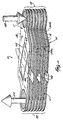
- Fig. 1 illustrates a core 10 for a recuperator used in a microturbine.
- the core 10 includes a plurality of stacked plate-fin cells 14 defining an inlet manifold 18 and an outlet manifold 22.
- each cell 14 includes top and bottom plates or sheets 24, 28, an internal or matrix finned member 32, inlet and outlet header finned members 34, 36 respectively, and external finned members 40.
- the top and bottom plates 24, 28 define manifold openings 42 that align to define the manifolds 18, 22.
- the manifold openings 42 are circular and the manifolds 18, 22 are cylindrical in the illustrated embodiment, but could have other configurations.
- the core 10 is characterized by a substantially isothermal and relatively cool portion C around the inlet manifold 18 and above and below the inlet header finned members 34.
- the flow of air enters the core 10 and the spent products of combustion exit the core 10 through the substantially isothermal cool portion C.
- the core 10 is also characterized by a substantially isothermal and relatively hot portion H around the outlet manifold 22 and above and below the outlet header finned members 36. The hot products of combustion enter the core 10 and the heated flow of air exits the core 10 through the substantially isothermal hot portion H.
- a matrix portion M (defined generally between the broken lines 54a and 54b in Fig. 1 ) of the core 10, is disposed between the hot and cool portions H, C of the core 10 and above and below the external finned members 40 and matrix finned members 32. Most of the heat transfer between the air and products of combustion takes place in the matrix portion M of the core 10.
- a hot fluid flow region is defined between the cells 14 and along the external finned members 40, and a cool fluid flow region is defined within the cells 14 and along the matrix finned members 32.
- a hot fluid flow region is defined between the cells 14 and along the external finned members 40, and a cool fluid flow region is defined within the cells 14 and along the matrix finned members 32.
- an end sheet or top sheet 56 is provided on top of the core 10.
- the uppermost hot fluid flow region is defined between the top sheet 56 and the cell 14 at the top of the core 10.
- the top sheet 56 includes first and second ends 57, 58, positioned over the substantially isothermal cool and hot portions C, H, respectively, and a middle portion 59 disposed between the first and second ends 57, 58.
- a window 60 ( Fig. 2 ) is cut into the middle portion 59 of the top sheet 56.
- a matrix cover 64 which is preferably the portion of the top sheet 56 cut out when the window 60 is created, is positioned within the window 60.
- Compliant strips or ligament portions 66 therefore run alongside the window 60 and interconnect the first and second ends 57,58 of the top sheet 56.
- the window 60 is positioned directly over the top external finned member 40.
- the window 60 is slightly smaller in at least one dimension (e. g., length and/or width) than the external finned member 40 so that the external finned member 40 does not extend through the window 60.
- a kerf 68 is created during formation of the window 60 and surrounds the matrix cover 64.
- the window 60 is preferably created with a laser cutting process, and the kerf 68 is therefore preferably about 0.03 inches (0.76mm) wide.
- the kerf 68 illustrated in the drawings is greatly exaggerated for the purposes of illustration and is not drawn to scale.
- a top frame plate 72 is positioned over the top sheet 56 and covers the kerf 68 to minimize leakage of products of combustion through the kerf 68.
- the top frame plate 72 is preferably fixed to a frame surrounding the core 10 such that the top frame plate 72 restricts vertical expansion of the core 10 during thermal cycles.
- the top frame plate 72 may be resiliently biased down onto the top sheet 56 by springs or other biasing members such that vertical thermal expansion of the core 10 is permitted while the top frame plate 72 is held firmly against the top sheet 56.
- the kerf 68 may not completely surround the matrix cover 64.
- bridges of material 76 are left intact between the matrix cover 64 and the top sheet 56. This embodiment may improve handling of the top sheet 56 and matrix cover 64 because they are interconnected and may be handled together. Additionally, this embodiment ensures that the matrix cover 64 is centered in the window 60. Also, once the heat exchanger is set up, it should not be a problem if the bridges 76 crack or break during thermal cycles because the matrix cover 64 is sandwiched between the top frame plate 72 and the top cell 14 of the core 10.
- the hot and cool portions H, C of the core 10 are subject to a substantially isothermal load, and the matrix portion M is exposed to the temperature gradient. Because the first and second ends 57, 58 of the top sheet 56 are connected only by the ligament portions 66, the middle portion 59 of the top sheet 56 is better able to accommodate the temperature gradient and the strain on and deflection of the first and second ends 57, 58 are reduced.
- the ligament portions 66 may therefore be referred to as compliant portions of the top sheet 56.
- ligament portions 66 are not necessarily drawn to scale in the drawings. It is preferably that the ligament portions 66 are longer (i. e., in the direction extending between the ends 57, 58) than wide to enhance their compliant nature. In practice the ligament portions 66 may be made longer and narrower than illustrated.
Landscapes
- Engineering & Computer Science (AREA)
- Physics & Mathematics (AREA)
- Thermal Sciences (AREA)
- Mechanical Engineering (AREA)
- General Engineering & Computer Science (AREA)
- Heat-Exchange Devices With Radiators And Conduit Assemblies (AREA)
- Bending Of Plates, Rods, And Pipes (AREA)
Claims (7)
- Wärmeaustauscher, der Folgendes umfasst: einen Kern (10), der eine gestapelte Anordnung von Blechrippenzellen (14) einschließt, wobei der Kern (10) dafür eingerichtet ist, Luft, die durch die Zellen (14) strömt, mit heißen Gasen, die zwischen den Zellen (14) strömen, zu erhitzen,
wobei der Kern (10) einen im Wesentlichen isothermischen kühlen Abschnitt (C), in dem der Luftstrom in die Zellen (14) eintritt und aus dem der Strom von heißen Gasen aus dem Kern (10) zwischen den Zellen (14) austritt, einen im Wesentlichen isothermischen heißen Abschnitt (H), in dem der Strom von heißen Gasen in den Kern (10) zwischen den Zellen (14) eintritt und aus dem der Luftstrom aus den Zellen (14) austritt, und einen Matrizenabschnitt (M) zwischen den im Wesentlichen isothermischen heißen und kühlen Abschnitten (H, C) einschließt,
wobei die Luft und die heißen Gase in einer Gegenstrombeziehung zueinander durch den Matrizenabschnitt (M) strömen, wobei die Luft durch die Zellen (14) strömt und die heißen Gase zwischen den Zellen (14) strömen, wobei der Großteil der Wärmeübertragung zwischen den Strömen von Luft und heißen Gasen innerhalb des Matrizenabschnitts (M) auftritt, um ein Temperaturgefälle über den Matrizenabschnitt (M) herzustellen,
eine obere Tafel (56), die über dem Kern (10) angeordnet ist und ein erstes und ein zweites Ende (57, 58) und einen Mittelabschnitt (59) zwischen dem ersten und dem zweiten Ende (57, 58) einschließt,
wobei das erste und das zweite Ende (57, 58) der oberen Tafel (56) über dem isothermischen kühlen bzw. heißen Abschnitt (C, H) des Kerns (10) angeordnet sind und der Mittelabschnitt (59) der oberen Tafel (56) über dem Matrizenabschnitt (M) des Kerns (10) angeordnet ist, dadurch gekennzeichnct, dass der Mittelabschnitt (59) ein Fenster (60) und nachgiebige Bandabschnitte (66), die sich längsseits des Fensters (60) erstrecken und das erste und das zweite Ende (57, 58) miteinander verbinden, einschließt,
wobei die nachgiebigen Bandabschnitte (66) der oberen Tafel (56) als Reaktion auf das Temperaturgefälle über den Matrizenabschnitt (M) des Kerns (10) abgelenkt werden können, um eine Beanspruchung an dem ersten und dem zweiten Ende (57, 58) der oberen Tafel (56) und eine Ablenkung derselben zu verringern, und
der ferner eine Matrizenabdeckung (64) umfasst, die innerhalb des Fensters angeordnet ist. - Wärmeaustauscher nach Anspruch 1, wobei eine Kerbe (68) zwischen der Matrizenabdeckung (64) und der oberen Tafel (56) definiert wird.
- Wärmeaustauscher nach Anspruch 2, der ferner eine obere Rahmenplatte (72) umfasst, die derart über der oberen Tafel (56) angeordnet ist, dass die obere Tafel (56) zwischen der oberen Rahmenplatte (72) und dem Kern (10) eingeschoben ist, um einem Fluidstrom durch die Kerbe (68) zu widerstehen.
- Wärmeaustauscher nach Anspruch 2 oder Anspruch 3, wobei die Kerbe (68) den gesamten Umfang der Matrizenabdeckung (64) umschließt, mit Ausnahme wenigstens einer Materialbrücke (76), welche die Matrizenabdeckung (64) mit wenigstens einem der Bandabschnitte (66) verbindet.
- Wärmeaustauscher nach einem der Ansprüche 1 bis 3, wobei die Matrizenabdeckung (64) einen Abschnitt der oberen Tafel (56) einschließt, der aus dem Mittelabschnitt (59) der oberen Tafel (56) geschnitten ist und vollständig von demselben entfernt werden kann.
- Wärmeaustauscher nach einem der vorhergehenden Ansprüche, wobei jede Zelle (14) ein äußeres mit Rippen versehenes Element (40) einschließt, das an einer Außenfläche der Zelle (14) befestigt ist,
wobei die obere Tafel (56) über dem äußeren mit Rippen versehenen Element (40) der oberen Zelle (14) des Kerns (10) angeordnet ist, um einen Heißfluid-Strömungsbereich zwischen denselben zu definieren, um den Strom von heißen Gasen aufzunehmen, und wobei das Fenster (60) über dem äußeren mit Rippen versehenen Element (40) angeordnet ist. - Wärmeaustauscher nach Anspruch 6, wobei das äußere mit Rippen versehene Element (40) in wenigstens einer Abmessung größer als das Fenster (60) ist, um zu verhindern, dass sich das äußere mit Rippen versehene Element (40) durch das Fenster (60) erstreckt.
Applications Claiming Priority (3)
| Application Number | Priority Date | Filing Date | Title |
|---|---|---|---|
| US904788 | 1992-06-26 | ||
| US09/904,788 US6427764B2 (en) | 1996-02-01 | 2001-07-13 | Heat exchanger having selectively compliant end sheet |
| PCT/US2002/022380 WO2003006907A2 (en) | 2001-07-13 | 2002-07-15 | Heat exchanger having selectively compliant end sheet |
Publications (3)
| Publication Number | Publication Date |
|---|---|
| EP1407210A2 EP1407210A2 (de) | 2004-04-14 |
| EP1407210A4 EP1407210A4 (de) | 2006-01-11 |
| EP1407210B1 true EP1407210B1 (de) | 2008-11-19 |
Family
ID=25419780
Family Applications (1)
| Application Number | Title | Priority Date | Filing Date |
|---|---|---|---|
| EP02756481A Expired - Lifetime EP1407210B1 (de) | 2001-07-13 | 2002-07-15 | Wärmetauscher mit gezielt nachgiebiger endplatte |
Country Status (6)
| Country | Link |
|---|---|
| US (1) | US6427764B2 (de) |
| EP (1) | EP1407210B1 (de) |
| AT (1) | ATE414880T1 (de) |
| DE (1) | DE60229946D1 (de) |
| ES (1) | ES2315381T3 (de) |
| WO (1) | WO2003006907A2 (de) |
Families Citing this family (8)
| Publication number | Priority date | Publication date | Assignee | Title |
|---|---|---|---|---|
| NL1020483C1 (nl) * | 2002-04-26 | 2003-10-28 | Oxycell Holding Bv | Warmtewisselaar en werkwijze voor het vervaardigen daarvan. |
| US20040164695A1 (en) * | 2003-02-26 | 2004-08-26 | William M. Hallidy | Electrodynamic machines and components therefor and methods of making and using same |
| US6991026B2 (en) * | 2004-06-21 | 2006-01-31 | Ingersoll-Rand Energy Systems | Heat exchanger with header tubes |
| DE102009050889A1 (de) * | 2009-10-27 | 2011-04-28 | Behr Gmbh & Co. Kg | Abgasverdampfer |
| FR2955928B1 (fr) * | 2010-01-29 | 2012-06-01 | Valeo Systemes Thermiques | Echangeur de chaleur |
| JP5545260B2 (ja) * | 2010-05-21 | 2014-07-09 | 株式会社デンソー | 熱交換器 |
| FR2980837B1 (fr) * | 2011-10-04 | 2015-06-26 | Valeo Systemes Thermiques | Echangeur de chaleur a plaques empilees. |
| WO2014064334A1 (en) * | 2012-10-22 | 2014-05-01 | Ekogen Oy | Method and apparatus for thermal energy conversion |
Family Cites Families (11)
| Publication number | Priority date | Publication date | Assignee | Title |
|---|---|---|---|---|
| US1099896A (en) | 1911-02-01 | 1914-06-09 | Detroit Can Company | Pouring-spout for paper or fibrous-material cans or receptacles. |
| GB975071A (en) * | 1962-03-30 | 1964-11-11 | Parsons C A & Co Ltd | Plate type heat exchangers |
| US3322189A (en) * | 1965-12-21 | 1967-05-30 | Ford Motor Co | Heat exchange assembly |
| CA996923A (en) * | 1973-04-16 | 1976-09-14 | Kenneth O. Parker | Formed plate heat exchanger and method of fabricating |
| US4291754A (en) * | 1978-10-26 | 1981-09-29 | The Garrett Corporation | Thermal management of heat exchanger structure |
| FR2625301A3 (fr) * | 1987-12-23 | 1989-06-30 | Valeo Chausson Thermique | Echangeur de chaleur a plaques, notamment pour vehicule automobile, et procede de fabrication permettant d'obtenir un tel echangeur |
| US5186239A (en) * | 1992-01-30 | 1993-02-16 | Ford Motor Company | Heat exchanger with thermal stress relieving zone |
| ES2127472T3 (es) * | 1994-04-12 | 1999-04-16 | Showa Aluminum Corp | Intercambiador de calor duplex de tipo apilado. |
| PL328065A1 (en) | 1996-02-01 | 1999-01-04 | Northern Res & Eng | Plate-and-ribs heat exchanger of unitary construction |
| FR2788116B1 (fr) * | 1998-12-30 | 2001-05-18 | Valeo Climatisation | Dispositif de chauffage, ventilation et/ou climatisation comportant une boucle thermique equipee d'un evaporateur |
| JP2000329493A (ja) * | 1999-05-20 | 2000-11-30 | Toyo Radiator Co Ltd | 積層型熱交換器 |
-
2001
- 2001-07-13 US US09/904,788 patent/US6427764B2/en not_active Expired - Fee Related
-
2002
- 2002-07-15 EP EP02756481A patent/EP1407210B1/de not_active Expired - Lifetime
- 2002-07-15 ES ES02756481T patent/ES2315381T3/es not_active Expired - Lifetime
- 2002-07-15 DE DE60229946T patent/DE60229946D1/de not_active Expired - Lifetime
- 2002-07-15 AT AT02756481T patent/ATE414880T1/de not_active IP Right Cessation
- 2002-07-15 WO PCT/US2002/022380 patent/WO2003006907A2/en not_active Ceased
Also Published As
| Publication number | Publication date |
|---|---|
| EP1407210A2 (de) | 2004-04-14 |
| EP1407210A4 (de) | 2006-01-11 |
| WO2003006907A2 (en) | 2003-01-23 |
| ATE414880T1 (de) | 2008-12-15 |
| ES2315381T3 (es) | 2009-04-01 |
| WO2003006907A3 (en) | 2003-04-10 |
| US20010040023A1 (en) | 2001-11-15 |
| US6427764B2 (en) | 2002-08-06 |
| DE60229946D1 (de) | 2009-01-02 |
Similar Documents
| Publication | Publication Date | Title |
|---|---|---|
| US6460613B2 (en) | Dual-density header fin for unit-cell plate-fin heat exchanger | |
| EP0530181B1 (de) | Kreisförmiger wärmetauscher | |
| US4301863A (en) | Heat exchanger closure bar construction | |
| US4229868A (en) | Apparatus for reinforcement of thin plate, high pressure fluid heat exchangers | |
| CA2245000C (en) | Unit construction plate-fin heat exchanger | |
| US8028410B2 (en) | Gas turbine regenerator apparatus and method of manufacture | |
| US4253520A (en) | Heat exchanger construction | |
| US8215378B2 (en) | Heat exchanger with pressure and thermal strain management | |
| EP0530188A1 (de) | Ringförmiger wärmetauscher mit gleichförmigem durchgangsquerschnitt. | |
| US6427764B2 (en) | Heat exchanger having selectively compliant end sheet | |
| EP1281921A2 (de) | Gegenstrom-Plattenwärmetauscher mit Rippen und Verteilungsrippe | |
| JPH02275292A (ja) | 熱交換器 | |
| JP2927367B2 (ja) | 環状熱交換器用の熱拘束装置 | |
| WO2004005829A1 (en) | Crossflow heat exchanger with cells formed by plates and fins forming u-shaped flow path | |
| WO2010082382A1 (ja) | 一次伝面型熱交換器 | |
| JPH09273886A (ja) | 積層型熱交換器 | |
| EP3077752B1 (de) | Wärmetauscher mit verbesserter festigkeit | |
| US5909767A (en) | Recuperative cross flow plate-type heat exchanger | |
| JP4352504B2 (ja) | プレート・フィン型熱交換器 | |
| US20030226655A1 (en) | Primary surface recuperator sheet | |
| US20060060335A1 (en) | Heat exchanger with compound plates | |
| US20250362090A1 (en) | Heat exchanger | |
| JPS6339581Y2 (de) | ||
| JPS6339582Y2 (de) |
Legal Events
| Date | Code | Title | Description |
|---|---|---|---|
| PUAI | Public reference made under article 153(3) epc to a published international application that has entered the european phase |
Free format text: ORIGINAL CODE: 0009012 |
|
| 17P | Request for examination filed |
Effective date: 20040203 |
|
| AK | Designated contracting states |
Kind code of ref document: A2 Designated state(s): AT BE BG CH CY CZ DE DK EE ES FI FR GB GR IE IT LI LU MC NL PT SE SK TR |
|
| RIN1 | Information on inventor provided before grant (corrected) |
Inventor name: NASH, JAMES, S. |
|
| A4 | Supplementary search report drawn up and despatched |
Effective date: 20051124 |
|
| RIC1 | Information provided on ipc code assigned before grant |
Ipc: F28D 1/03 19850101AFI20030124BHEP Ipc: F28F 9/00 19680901ALI20051119BHEP Ipc: F28D 9/00 19680901ALI20051119BHEP |
|
| GRAP | Despatch of communication of intention to grant a patent |
Free format text: ORIGINAL CODE: EPIDOSNIGR1 |
|
| GRAS | Grant fee paid |
Free format text: ORIGINAL CODE: EPIDOSNIGR3 |
|
| GRAA | (expected) grant |
Free format text: ORIGINAL CODE: 0009210 |
|
| AK | Designated contracting states |
Kind code of ref document: B1 Designated state(s): AT BE BG CH CY CZ DE DK EE ES FI FR GB GR IE IT LI LU MC NL PT SE SK TR |
|
| REG | Reference to a national code |
Ref country code: GB Ref legal event code: FG4D |
|
| REG | Reference to a national code |
Ref country code: CH Ref legal event code: EP |
|
| REG | Reference to a national code |
Ref country code: IE Ref legal event code: FG4D |
|
| REF | Corresponds to: |
Ref document number: 60229946 Country of ref document: DE Date of ref document: 20090102 Kind code of ref document: P |
|
| REG | Reference to a national code |
Ref country code: ES Ref legal event code: FG2A Ref document number: 2315381 Country of ref document: ES Kind code of ref document: T3 |
|
| PG25 | Lapsed in a contracting state [announced via postgrant information from national office to epo] |
Ref country code: AT Free format text: LAPSE BECAUSE OF FAILURE TO SUBMIT A TRANSLATION OF THE DESCRIPTION OR TO PAY THE FEE WITHIN THE PRESCRIBED TIME-LIMIT Effective date: 20081119 |
|
| NLV1 | Nl: lapsed or annulled due to failure to fulfill the requirements of art. 29p and 29m of the patents act | ||
| PG25 | Lapsed in a contracting state [announced via postgrant information from national office to epo] |
Ref country code: FI Free format text: LAPSE BECAUSE OF FAILURE TO SUBMIT A TRANSLATION OF THE DESCRIPTION OR TO PAY THE FEE WITHIN THE PRESCRIBED TIME-LIMIT Effective date: 20081119 Ref country code: NL Free format text: LAPSE BECAUSE OF FAILURE TO SUBMIT A TRANSLATION OF THE DESCRIPTION OR TO PAY THE FEE WITHIN THE PRESCRIBED TIME-LIMIT Effective date: 20081119 |
|
| PG25 | Lapsed in a contracting state [announced via postgrant information from national office to epo] |
Ref country code: BG Free format text: LAPSE BECAUSE OF FAILURE TO SUBMIT A TRANSLATION OF THE DESCRIPTION OR TO PAY THE FEE WITHIN THE PRESCRIBED TIME-LIMIT Effective date: 20090219 Ref country code: BE Free format text: LAPSE BECAUSE OF FAILURE TO SUBMIT A TRANSLATION OF THE DESCRIPTION OR TO PAY THE FEE WITHIN THE PRESCRIBED TIME-LIMIT Effective date: 20081119 Ref country code: EE Free format text: LAPSE BECAUSE OF FAILURE TO SUBMIT A TRANSLATION OF THE DESCRIPTION OR TO PAY THE FEE WITHIN THE PRESCRIBED TIME-LIMIT Effective date: 20081119 Ref country code: DK Free format text: LAPSE BECAUSE OF FAILURE TO SUBMIT A TRANSLATION OF THE DESCRIPTION OR TO PAY THE FEE WITHIN THE PRESCRIBED TIME-LIMIT Effective date: 20081119 |
|
| PG25 | Lapsed in a contracting state [announced via postgrant information from national office to epo] |
Ref country code: SE Free format text: LAPSE BECAUSE OF FAILURE TO SUBMIT A TRANSLATION OF THE DESCRIPTION OR TO PAY THE FEE WITHIN THE PRESCRIBED TIME-LIMIT Effective date: 20090219 Ref country code: PT Free format text: LAPSE BECAUSE OF FAILURE TO SUBMIT A TRANSLATION OF THE DESCRIPTION OR TO PAY THE FEE WITHIN THE PRESCRIBED TIME-LIMIT Effective date: 20090420 Ref country code: CZ Free format text: LAPSE BECAUSE OF FAILURE TO SUBMIT A TRANSLATION OF THE DESCRIPTION OR TO PAY THE FEE WITHIN THE PRESCRIBED TIME-LIMIT Effective date: 20081119 |
|
| PLBE | No opposition filed within time limit |
Free format text: ORIGINAL CODE: 0009261 |
|
| STAA | Information on the status of an ep patent application or granted ep patent |
Free format text: STATUS: NO OPPOSITION FILED WITHIN TIME LIMIT |
|
| PG25 | Lapsed in a contracting state [announced via postgrant information from national office to epo] |
Ref country code: SK Free format text: LAPSE BECAUSE OF FAILURE TO SUBMIT A TRANSLATION OF THE DESCRIPTION OR TO PAY THE FEE WITHIN THE PRESCRIBED TIME-LIMIT Effective date: 20081119 |
|
| 26N | No opposition filed |
Effective date: 20090820 |
|
| PG25 | Lapsed in a contracting state [announced via postgrant information from national office to epo] |
Ref country code: MC Free format text: LAPSE BECAUSE OF NON-PAYMENT OF DUE FEES Effective date: 20090731 |
|
| REG | Reference to a national code |
Ref country code: CH Ref legal event code: PL |
|
| REG | Reference to a national code |
Ref country code: IE Ref legal event code: MM4A |
|
| PG25 | Lapsed in a contracting state [announced via postgrant information from national office to epo] |
Ref country code: LI Free format text: LAPSE BECAUSE OF NON-PAYMENT OF DUE FEES Effective date: 20090731 Ref country code: CH Free format text: LAPSE BECAUSE OF NON-PAYMENT OF DUE FEES Effective date: 20090731 |
|
| PG25 | Lapsed in a contracting state [announced via postgrant information from national office to epo] |
Ref country code: IE Free format text: LAPSE BECAUSE OF NON-PAYMENT OF DUE FEES Effective date: 20090715 |
|
| PG25 | Lapsed in a contracting state [announced via postgrant information from national office to epo] |
Ref country code: GR Free format text: LAPSE BECAUSE OF FAILURE TO SUBMIT A TRANSLATION OF THE DESCRIPTION OR TO PAY THE FEE WITHIN THE PRESCRIBED TIME-LIMIT Effective date: 20090220 |
|
| PG25 | Lapsed in a contracting state [announced via postgrant information from national office to epo] |
Ref country code: LU Free format text: LAPSE BECAUSE OF NON-PAYMENT OF DUE FEES Effective date: 20090715 |
|
| REG | Reference to a national code |
Ref country code: GB Ref legal event code: 732E Free format text: REGISTERED BETWEEN 20110512 AND 20110518 |
|
| REG | Reference to a national code |
Ref country code: DE Ref legal event code: R082 Ref document number: 60229946 Country of ref document: DE Representative=s name: MARKS & CLERK (LUXEMBOURG) LLP, LU |
|
| PG25 | Lapsed in a contracting state [announced via postgrant information from national office to epo] |
Ref country code: TR Free format text: LAPSE BECAUSE OF FAILURE TO SUBMIT A TRANSLATION OF THE DESCRIPTION OR TO PAY THE FEE WITHIN THE PRESCRIBED TIME-LIMIT Effective date: 20081119 |
|
| REG | Reference to a national code |
Ref country code: DE Ref legal event code: R082 Ref document number: 60229946 Country of ref document: DE Representative=s name: MARKS & CLERK (LUXEMBOURG) LLP, LU Effective date: 20110707 Ref country code: DE Ref legal event code: R081 Ref document number: 60229946 Country of ref document: DE Owner name: FLEXENERGY ENERGY SYSTEMS, INC., US Free format text: FORMER OWNER: INGERSOLL-RAND ENERGY SYSTEMS CORP., PORTSMOUTH, N.H., US Effective date: 20110707 |
|
| PG25 | Lapsed in a contracting state [announced via postgrant information from national office to epo] |
Ref country code: CY Free format text: LAPSE BECAUSE OF FAILURE TO SUBMIT A TRANSLATION OF THE DESCRIPTION OR TO PAY THE FEE WITHIN THE PRESCRIBED TIME-LIMIT Effective date: 20081119 |
|
| REG | Reference to a national code |
Ref country code: FR Ref legal event code: TP Owner name: FLEXENERGY ENERGY SYSTEMS, INC., US Effective date: 20120423 |
|
| REG | Reference to a national code |
Ref country code: ES Ref legal event code: PC2A Owner name: FLEXENERGY ENERGY SYSTEMS, INC. Effective date: 20120521 |
|
| REG | Reference to a national code |
Ref country code: FR Ref legal event code: CA Effective date: 20121105 |
|
| PGFP | Annual fee paid to national office [announced via postgrant information from national office to epo] |
Ref country code: ES Payment date: 20130628 Year of fee payment: 12 Ref country code: DE Payment date: 20130711 Year of fee payment: 12 |
|
| PGFP | Annual fee paid to national office [announced via postgrant information from national office to epo] |
Ref country code: GB Payment date: 20130710 Year of fee payment: 12 Ref country code: FR Payment date: 20130724 Year of fee payment: 12 |
|
| PGFP | Annual fee paid to national office [announced via postgrant information from national office to epo] |
Ref country code: IT Payment date: 20130715 Year of fee payment: 12 |
|
| REG | Reference to a national code |
Ref country code: DE Ref legal event code: R119 Ref document number: 60229946 Country of ref document: DE |
|
| GBPC | Gb: european patent ceased through non-payment of renewal fee |
Effective date: 20140715 |
|
| REG | Reference to a national code |
Ref country code: FR Ref legal event code: ST Effective date: 20150331 |
|
| PG25 | Lapsed in a contracting state [announced via postgrant information from national office to epo] |
Ref country code: IT Free format text: LAPSE BECAUSE OF NON-PAYMENT OF DUE FEES Effective date: 20140715 Ref country code: DE Free format text: LAPSE BECAUSE OF NON-PAYMENT OF DUE FEES Effective date: 20150203 |
|
| REG | Reference to a national code |
Ref country code: DE Ref legal event code: R119 Ref document number: 60229946 Country of ref document: DE Effective date: 20150203 |
|
| PG25 | Lapsed in a contracting state [announced via postgrant information from national office to epo] |
Ref country code: FR Free format text: LAPSE BECAUSE OF NON-PAYMENT OF DUE FEES Effective date: 20140731 Ref country code: GB Free format text: LAPSE BECAUSE OF NON-PAYMENT OF DUE FEES Effective date: 20140715 |
|
| PG25 | Lapsed in a contracting state [announced via postgrant information from national office to epo] |
Ref country code: ES Free format text: LAPSE BECAUSE OF NON-PAYMENT OF DUE FEES Effective date: 20140716 |