EP1407246B1 - Dispositif de prelevement d'echantillons d'eaux usees avec un dispositif de filtration qui est nettoye electrolytiquement - Google Patents
Dispositif de prelevement d'echantillons d'eaux usees avec un dispositif de filtration qui est nettoye electrolytiquement Download PDFInfo
- Publication number
- EP1407246B1 EP1407246B1 EP02769131A EP02769131A EP1407246B1 EP 1407246 B1 EP1407246 B1 EP 1407246B1 EP 02769131 A EP02769131 A EP 02769131A EP 02769131 A EP02769131 A EP 02769131A EP 1407246 B1 EP1407246 B1 EP 1407246B1
- Authority
- EP
- European Patent Office
- Prior art keywords
- filter
- chamber
- filter mesh
- chamber housing
- cathode
- Prior art date
- Legal status (The legal status is an assumption and is not a legal conclusion. Google has not performed a legal analysis and makes no representation as to the accuracy of the status listed.)
- Expired - Lifetime
Links
- 239000002351 wastewater Substances 0.000 title claims abstract description 25
- 238000005375 photometry Methods 0.000 claims abstract description 7
- 239000012811 non-conductive material Substances 0.000 claims description 10
- 239000002184 metal Substances 0.000 claims description 7
- 239000000919 ceramic Substances 0.000 claims description 3
- 239000011248 coating agent Substances 0.000 claims description 3
- 238000000576 coating method Methods 0.000 claims description 3
- 239000004020 conductor Substances 0.000 claims description 2
- 230000003647 oxidation Effects 0.000 abstract description 10
- 238000007254 oxidation reaction Methods 0.000 abstract description 10
- 239000000706 filtrate Substances 0.000 abstract description 9
- 238000004140 cleaning Methods 0.000 description 18
- 238000000034 method Methods 0.000 description 11
- 238000005070 sampling Methods 0.000 description 8
- 238000004458 analytical method Methods 0.000 description 6
- 238000001914 filtration Methods 0.000 description 6
- 239000003153 chemical reaction reagent Substances 0.000 description 4
- 238000005868 electrolysis reaction Methods 0.000 description 4
- 239000007800 oxidant agent Substances 0.000 description 4
- 239000003792 electrolyte Substances 0.000 description 3
- 239000007787 solid Substances 0.000 description 3
- XLYOFNOQVPJJNP-UHFFFAOYSA-N water Substances O XLYOFNOQVPJJNP-UHFFFAOYSA-N 0.000 description 3
- 238000011065 in-situ storage Methods 0.000 description 2
- 239000000126 substance Substances 0.000 description 2
- 238000002048 anodisation reaction Methods 0.000 description 1
- 238000011001 backwashing Methods 0.000 description 1
- 244000052616 bacterial pathogen Species 0.000 description 1
- 230000015572 biosynthetic process Effects 0.000 description 1
- 239000012459 cleaning agent Substances 0.000 description 1
- 239000000470 constituent Substances 0.000 description 1
- 238000010276 construction Methods 0.000 description 1
- 230000000694 effects Effects 0.000 description 1
- 230000005684 electric field Effects 0.000 description 1
- 238000000605 extraction Methods 0.000 description 1
- 239000012530 fluid Substances 0.000 description 1
- 238000012423 maintenance Methods 0.000 description 1
- 238000005259 measurement Methods 0.000 description 1
- 230000003287 optical effect Effects 0.000 description 1
- 238000005457 optimization Methods 0.000 description 1
- 239000011148 porous material Substances 0.000 description 1
- 239000000047 product Substances 0.000 description 1
- 230000000717 retained effect Effects 0.000 description 1
- 238000007789 sealing Methods 0.000 description 1
- 125000006850 spacer group Chemical group 0.000 description 1
- 238000003860 storage Methods 0.000 description 1
Images

Classifications
-
- G—PHYSICS
- G01—MEASURING; TESTING
- G01N—INVESTIGATING OR ANALYSING MATERIALS BY DETERMINING THEIR CHEMICAL OR PHYSICAL PROPERTIES
- G01N1/00—Sampling; Preparing specimens for investigation
- G01N1/28—Preparing specimens for investigation including physical details of (bio-)chemical methods covered elsewhere, e.g. G01N33/50, C12Q
- G01N1/40—Concentrating samples
- G01N1/4077—Concentrating samples by other techniques involving separation of suspended solids
-
- G—PHYSICS
- G01—MEASURING; TESTING
- G01N—INVESTIGATING OR ANALYSING MATERIALS BY DETERMINING THEIR CHEMICAL OR PHYSICAL PROPERTIES
- G01N33/00—Investigating or analysing materials by specific methods not covered by groups G01N1/00 - G01N31/00
- G01N33/18—Water
- G01N33/1886—Water using probes, e.g. submersible probes, buoys
-
- G—PHYSICS
- G01—MEASURING; TESTING
- G01N—INVESTIGATING OR ANALYSING MATERIALS BY DETERMINING THEIR CHEMICAL OR PHYSICAL PROPERTIES
- G01N1/00—Sampling; Preparing specimens for investigation
- G01N1/02—Devices for withdrawing samples
- G01N1/10—Devices for withdrawing samples in the liquid or fluent state
- G01N2001/1031—Sampling from special places
- G01N2001/1043—Sampling from special places from sewers
Definitions
- the invention relates to a method for collecting wastewater samples, in particular for photometric analysis, wherein a Filtratmenge sucked through a filter mat and taken therefrom a sample amount and an analysis is supplied, wherein the filter mat is cleaned intermittently outside the sampling.
- the solid components of the wastewater In the analysis of wastewater samples, the solid components of the wastewater must be retained by filtration for sampling. In all analytical methods used, the solid components may clog the analyzer. In the photometric analysis, in which a color change is detected optically after addition of a color reagent, a turbidity caused by solid constituents of the wastewater sample would falsify the measurement result. Therefore, particularly effective filtration is required for the photometric analysis of wastewater samples.
- US Pat. No. 4,624,760 discloses a method for cleaning a porous, electrically conductive filter during use of the filter for filtering an aqueous process medium by setting up an electrochemical cell with the filter as the first electrode and a counter electrode and the process medium as the electrolyte, and operating the Cell under electrolysis of the electrolyte, whereby the filter produces a gaseous electrolysis product, with which the filter is cleaned.
- European Patent Application Publication No. 0686 420 A1 also discloses. Cleaning method for electrically conductive filters, wherein, as described above, the filter is used as an electrode of an electrochemical cell. To increase the cleaning efficiency, the polarity of the electrodes alternates between cleaning cycles.
- the object of the present invention is to provide an improved apparatus with an electrolytic cleaning method.
- the object is achieved by the device for taking water samples according to the independent claim. 1
- the device according to the invention for taking wastewater samples, in particular for photometric analysis, with a filter device has a filter chamber (2) closed by a filter mat (2), from which a sampling line is led out, the filter mat (5) at least superficially made of electrically conductive Material and is connected as an anode to a positive electrical voltage source and wherein at a distance from the filter mat (5) connected to a negative electric voltage source cathode (22, 34) is arranged, wherein the cathode of the filter mat is electrically insulated, wherein further Filter chamber (2) is formed in a chamber housing (3) made of electrically non-conductive material, which has one of the filter mat (5) spanned chamber opening (4), and the chamber housing (3) surrounding the chamber opening (4), electrically conductive Carrying ring (24) bears, against the edge of the filter mat (5) dur an electrically non-conductive clamping ring (25) is pressed, wherein the cathode is formed either as a filter mat surrounding the concentric annular electrode or as a spaced apart from the filter
- the filter mat is electrically conductive and is applied in an intermittently executed cleaning operations for performing anodic oxidation as an anode with a positive electrical potential, while a separate cathode is subjected to a negative electric potential.
- the filter mat is cleaned by an anodic oxidation.
- oxidants are formed by electrochemical means. The oxidants formed directly on the surface of the filter mat oxidize the biological growth and thus prevent the growth of the Filter openings.
- the sample water is subjected exclusively to a mechanical filtration, but not a chemical or electrochemical influence.
- this cleaning process can be used particularly advantageously in analysis devices that are immersed in the form of a buoy directly into the wastewater to be examined.
- the anodization can be carried out at relatively short intervals each in time so that a substantial increase in the flow resistance of the filter mat is prevented.
- the energy requirement is kept low. This is particularly advantageous for analysis devices that are immersed as a buoy in the wastewater to be examined (so-called in-situ analyzers).
- the amount of filtrate is sucked by generating a negative pressure through the filter mat into a filter chamber and that the negative pressure before and / or during the sampling of the filter chamber is largely reduced.
- the wastewater between the filter mat as the anode and the cathode used in the apparatus according to the invention as an electrolyte.
- the water that has been subjected to the electrolysis is discarded.
- the wastewater that is fed to the analysis has not been affected by an electrochemical process.
- the cathode is a ring electrode which concentrically surrounds the filter mat at a distance. This achieves a particularly simple and compact construction.
- the cathode is a spaced apart from the filter mat plate electrode.
- a particularly uniform electric field is formed between the filter mat as the anode and the cathode, so that the anodic oxidation is uniformly distributed in all areas of the filter mat.
- the filter mat is made of metal.
- Metal is electrically conductive and has a high mechanical strength.
- the filter mat can also consist of electrically non-conductive material, such as plastic or ceramic, which is provided with a metallic surface coating, which ensures the electrical conductivity at the surface of the filter mat.
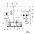
- the wastewater analyzer of the type of an in-situ analyzer shown schematically in FIG. 1 is designed as a buoy 1, which is immersed in the wastewater to be investigated.
- a filter chamber 2 is formed in a chamber housing 3 consisting of electrically non-conductive material.
- a chamber opening 4 of the filter chamber 2 is covered with a filter mat made of metal, wherein in FIG. 1, the inventive type of clamping the filter mat, not shown.
- a fill level sensor 6 projects into the filter chamber 2.
- a feed unit 7 serves to suck in a quantity of filtrate from the surrounding wastewater through the filter mat 5 into the filter chamber 2.
- An air line 8 is connected via a solenoid valve 9 and an electrically driven compressor 10 with a suction line 11 opening in the filter chamber 2.
- a sampling line 12 leads from the filter chamber via a solenoid valve 13 and a pump 14 to a photometric analyzer 15 having an optical sensor (not shown). From there, a drain line 16 leads out of the buoy 1.
- a storage container 17 for a color reagent is connected via a solenoid valve 18 and a pump 19 to the connecting line connected to the photometric analyzer 15 and is used to add a color reagent to be examined wastewater sample.
- the metal filter mat 5 is connected as an anode via an electrical line 20 to the positive output of an electrical DC voltage source 21.
- a ring electrode 22 surrounding the filter mat 5 is connected as a cathode via an electrical line 23 to the negative output of the electrical voltage source 21.
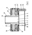
- the filter chamber 2 is formed in the chamber housing 3 made of electrically non-conductive material, the chamber opening 4 of which is spanned by the filter mat 5.
- the chamber housing 3 carries a surrounding the chamber opening 4, electrically conductive support ring 24 against which the edge of the filter mat 5 is pressed by a clamping ring 25 of electrically non-conductive material.
- the chamber housing 3 is interchangeably screwed to a housing bottom 27 by means of a centrally formed on the chamber housing 3, central screw 26.
- a device side arranged on the chamber housing 3 slip ring 28 is mechanically and electrically connected to the support ring 24 by a plurality of clamping screws 29.
- a concentric to the device side arranged on the chamber housing 3 slip ring 30 is also mechanically and electrically conductively connected via a plurality of axially parallel clamping screws 31 with the cathode forming ring electrode 22.
- the chamber housing 3 with the attached thereto Sharing is thus mounted as a unit easily replaceable on the bottom of the device 27.
- the two slip rings 28 and 30 are in each case in the device bottom 27 arranged electrical sliding contacts 32 and 33 into contact, which are guided through the existing electrically non-conductive material device bottom 27 and connected via the lines 20 and 23 to the electrical voltage source 21 are.
- the use of slip rings 28, 30 and sliding contacts 32, 33 ensures that, irrespective of the screwing position of the chamber housing 3 achieved in each case, an electrical connection between the filter mat 5 as anode and the ring electrode 22 as cathode with the electric DC voltage source 21 is provided.
- the filling of the filter chamber 2 is done in such a way that a negative pressure in the filter chamber 2 is first generated by the conveyor unit 7, so that a filtrate of the waste water to be examined is sucked through the filter mat 5 into the filter chamber 2.
- the solenoid valve 9 shown in Fig. 1 in its de-energized position is electrically applied.
- the compressor 10 is turned on. The compressor 10 sucks air through the suction line 11 and presses it through the air connection 8 to the outside. This process is continued until the level sensor 6 signals a sufficient filling of the filter chamber 2.
- the cleaning of the filter mat 5, in particular of biological growth, is carried out by an anodic oxidation.
- anodic oxidation By applying the electrically conductive filter mat 5 with a positive electrical potential by switching on the DC power source 21 and charging the cathode 22 with a negative electrical potential, oxidants are formed by electrolysis, wherein the oxidants formed on the filter mat as an anode oxidize the biological growth and thus the filter mat grows 5 prevent.
- This anodic oxidation cleaning operation is performed intermittently outside of the sampling, as often as necessary cyclically throughout the day.
- the conducted over the cathode and anode electrical power and / or the applied voltage is adapted to the respective cleaning requirements.
- the cleaning processes by anodic oxidation can be carried out parallel to the measuring operation in the analyzer 15 for time optimization.
- the filter mat 5 may be cleaned as required by supplying a separate chemical cleaning agent.
- Fig. 3 shows a comparison with the Fig. 2 modified embodiment of the cathode. While the cathode is designed in the embodiment of FIG. 2 as a filter mat 5 concentrically surrounding annular electrode 22, it is in the embodiment of FIG. 3 at a distance in front of the filter mat 5 arranged plate electrode 34, via a plurality of screws 35 and Spacer sleeves 36 is connected to a ring 22 ', which is equal to the ring electrode 22.
- the filter mat 5 made of metal, such as metal mesh, may also be provided, the filter mat 5 made of electrically non-conductive material, such as plastic or ceramic, and provided with a metallic surface coating to the required for anodic oxidation electrical conductivity to reach.
- electrically non-conductive material such as plastic or ceramic
- the edge of the filter mat 5 is pressed by the clamping ring 25 against a frustoconical surface 37 of the support ring 24 and is sealed by means of a sealing ring 38, for example an O-ring.
- the filter chamber 2 is a smooth continuous, for example, substantially cylindrical cavity.
- the chamber housing 3 or its screw socket 26 is sealed in the screwed-in state by means of a seal 39 relative to the housing bottom 27. This creates a simple mechanical cleaning option in the disassembled state.
- the suction line 11 opens into the filter chamber 2.
- the sampling line 12 and the level sensor 6 protrude from the area of the housing bottom 27 enclosed by the seal 39 into the filter chamber 2. This ensures that when the chamber housing 3 is replaced No connections for these lines 11, 12 and the level sensor 6 would have to be solved.
- the replacement of the filter mat 5 bearing chamber housing is thereby greatly facilitated and simplified, especially because of the electrical sliding contacts 23 and 32 and no electrical connection cables must be solved.
Landscapes
- Chemical & Material Sciences (AREA)
- Health & Medical Sciences (AREA)
- Life Sciences & Earth Sciences (AREA)
- Immunology (AREA)
- Analytical Chemistry (AREA)
- Biochemistry (AREA)
- General Health & Medical Sciences (AREA)
- General Physics & Mathematics (AREA)
- Physics & Mathematics (AREA)
- Pathology (AREA)
- Engineering & Computer Science (AREA)
- Food Science & Technology (AREA)
- Medicinal Chemistry (AREA)
- Sampling And Sample Adjustment (AREA)
- Electrostatic Separation (AREA)
- Electrical Discharge Machining, Electrochemical Machining, And Combined Machining (AREA)
- Investigating Or Analysing Materials By Optical Means (AREA)
- Water Treatment By Electricity Or Magnetism (AREA)
Claims (6)
- Dispositif destiné au prélèvement d'échantillons d'eaux usées, notamment pour analyse photométrique, équipé d'un dispositif de filtrage, qui comporte une chambre de filtrage (2) fermée par une toile filtrante (5), chambre depuis laquelle une conduite de prélèvement d'échantillons est sortie,
la toile filtrante (5) étant constituée au moins en surface d'une matière électroconductrice et étant raccordée en tant qu'anode à une source de tension électrique positive, et
une cathode (22, 34) raccordée à une source de tension électrique négative étant disposée à distance de la toile filtrante (5),
la cathode étant isolée électriquement de la toile filtrante, caractérisé en ce que
la chambre de filtrage (2) est formée dans un corps de chambre (3) constitué d'une matière non électroconductrice, corps qui présente une ouverture de chambre (4) recouverte par la toile filtrante (5), et en ce que
le corps de chambre (3) supporte une bague-support (24) électroconductrice enveloppant l'ouverture de chambre (4), bague-support contre laquelle le bord de la toile filtrante (5) est pressé par une bague de serrage (25) non électroconductrice,
la cathode étant
soit constituée d'une électrode annulaire enveloppant à distance la toile filtrante de façon concentrique
soit constituée d'une électrode à plaque disposée à distance devant la toile filtrante. - Dispositif selon la revendication 1, caractérisé en ce que la toile filtrante (5) est en métal.
- Dispositif selon la revendication 1, caractérisé en ce que la toile filtrante est constituée d'une matière non électroconductrice, par exemple en plastique ou en céramique, qui est pourvue d'un revêtement de surface métallique.
- Dispositif selon la revendication 1, caractérisé en ce que le corps de chambre (3) avec les pièces accolées est monté sur la partie inférieure de l'appareil (27) en tant qu'unité modulaire facilement interchangeable.
- Dispositif selon la revendication 4, caractérisé en ce que le corps de chambre (3) est vissé de façon interchangeable sur une partie inférieure de corps (27) au moyen d'un raccord fileté central (26), en ce qu'une bague glissante (28) reliée de façon électroconductrice avec la bague-support (24) et une bague glissante (30) reliée de façon électroconductrice avec la cathode (22 ou 34) sont disposées de façon concentrique côté appareil sur le corps de chambre (3) et sont chacune en contact avec des contacts électriques glissants (32 ou 33) disposés dans la partie inférieure d'appareil (27).
- Dispositif selon la revendication 4 ou 5, caractérisé en ce que la chambre de filtrage (2) est une cavité entièrement traversante, par exemple essentiellement cylindrique, et en ce que le corps de chambre (3) ou son raccord fileté (26) est rendu étanche à l'état vissé au moyen d'un joint d'étanchéité (39) par rapport à la partie inférieure de corps (27).
Applications Claiming Priority (3)
| Application Number | Priority Date | Filing Date | Title |
|---|---|---|---|
| DE10122801 | 2001-05-10 | ||
| DE10122801A DE10122801A1 (de) | 2001-05-10 | 2001-05-10 | Verfahren und Vorrichtung zur Entnahme von Abwasserproben |
| PCT/EP2002/004811 WO2002090937A2 (fr) | 2001-05-10 | 2002-05-02 | Procede et dispositif de prelevement d'echantillons d'eaux usees |
Publications (3)
| Publication Number | Publication Date |
|---|---|
| EP1407246A2 EP1407246A2 (fr) | 2004-04-14 |
| EP1407246B1 true EP1407246B1 (fr) | 2006-09-27 |
| EP1407246B8 EP1407246B8 (fr) | 2006-11-08 |
Family
ID=7684339
Family Applications (1)
| Application Number | Title | Priority Date | Filing Date |
|---|---|---|---|
| EP02769131A Expired - Lifetime EP1407246B8 (fr) | 2001-05-10 | 2002-05-02 | Dispositif de prelevement d'echantillons d'eaux usees avec un dispositif de filtration qui est nettoye electrolytiquement |
Country Status (8)
| Country | Link |
|---|---|
| US (1) | US20040232086A1 (fr) |
| EP (1) | EP1407246B8 (fr) |
| JP (1) | JP4072438B2 (fr) |
| AT (1) | ATE340992T1 (fr) |
| CA (1) | CA2446341A1 (fr) |
| DE (2) | DE10122801A1 (fr) |
| DK (1) | DK1407246T3 (fr) |
| WO (1) | WO2002090937A2 (fr) |
Families Citing this family (6)
| Publication number | Priority date | Publication date | Assignee | Title |
|---|---|---|---|---|
| US20120205301A1 (en) * | 2007-08-02 | 2012-08-16 | Mcguire Dennis | Apparatus for treating fluids |
| US8968577B2 (en) * | 2012-06-11 | 2015-03-03 | Ecosphere Technologies, Inc. | Process for treating fluids |
| US9266752B2 (en) | 2007-08-02 | 2016-02-23 | Ecosphere Technologies, Inc. | Apparatus for treating fluids |
| DE102011088235A1 (de) * | 2011-12-12 | 2013-06-13 | Endress + Hauser Conducta Gesellschaft für Mess- und Regeltechnik mbH + Co. KG | Probenvorbereitungseinrichtung für eine Analyseeinrichtung zur Bestimmung einer Messgröße einer flüssigen Probe |
| WO2018064761A1 (fr) * | 2016-10-03 | 2018-04-12 | 2134761 Ontario Ltd. | Système d'échantillonnage d'eau à haute teneur en solides |
| CN110174282A (zh) * | 2019-05-31 | 2019-08-27 | 新昌县以琳环保科技有限公司 | 污水处理过滤膜取样检测装置 |
Family Cites Families (16)
| Publication number | Priority date | Publication date | Assignee | Title |
|---|---|---|---|---|
| US4111768A (en) * | 1975-08-04 | 1978-09-05 | Ametek, Inc. | Method of separating solids from a fluid system |
| JPS5623287A (en) * | 1979-07-31 | 1981-03-05 | Asahi Chem Ind Co Ltd | Filter press type electrolytic cell |
| US4594138A (en) * | 1984-05-17 | 1986-06-10 | Thompson Donald E | Fluid filter |
| GB8415887D0 (en) * | 1984-06-21 | 1984-07-25 | Atomic Energy Authority Uk | Membrane cleaning |
| US4933080A (en) * | 1989-01-13 | 1990-06-12 | Associated Mills Inc. | Housing with replaceable filter cartridge for use with shower head |
| GB8901581D0 (en) * | 1989-01-25 | 1989-03-15 | Alcan Int Ltd | Filter cleaning |
| US5167802A (en) * | 1990-07-26 | 1992-12-01 | The United States Of America As Represented By The Secretary Of The Interior | Apparatus for sampling pesticide residues in run-off with control of sample pump and distributor valve |
| GB9019216D0 (en) * | 1990-08-31 | 1990-10-17 | Atomic Energy Authority Uk | Filter cleaning |
| US5126041A (en) * | 1991-01-18 | 1992-06-30 | Emerson Electric Co. | Faucet with removable filter for a water distiller |
| US5167804A (en) * | 1991-05-16 | 1992-12-01 | Tigg Corporation | Liquid treatment system |
| DE4301270A1 (de) * | 1992-07-17 | 1994-01-20 | P & P Geotechnik Gmbh | Verfahren und Einrichtung zur Beseitigung von Schadstoffen, insbesondere im Erdbodenbereich |
| DK0654015T3 (da) * | 1992-08-10 | 1997-06-23 | Protec Partner F R Umwelttechn | Fremgangsmåde og apparat til biologisk behandling af organisk belastet spildevand og organisk affald |
| JP3176175B2 (ja) * | 1993-03-04 | 2001-06-11 | キヤノン株式会社 | 画像記録方法 |
| GB9411580D0 (en) * | 1994-06-09 | 1994-08-03 | Atomic Energy Authority Uk | Filter cleaning |
| GB9525558D0 (en) * | 1995-12-14 | 1996-02-14 | Head Philip | A system for coiled tubing |
| GB9924588D0 (en) * | 1999-10-19 | 1999-12-22 | Snowball Malcolm R | Fluid sampling |
-
2001
- 2001-05-10 DE DE10122801A patent/DE10122801A1/de not_active Withdrawn
-
2002
- 2002-05-02 WO PCT/EP2002/004811 patent/WO2002090937A2/fr not_active Ceased
- 2002-05-02 AT AT02769131T patent/ATE340992T1/de not_active IP Right Cessation
- 2002-05-02 CA CA002446341A patent/CA2446341A1/fr not_active Abandoned
- 2002-05-02 EP EP02769131A patent/EP1407246B8/fr not_active Expired - Lifetime
- 2002-05-02 DE DE50208269T patent/DE50208269D1/de not_active Expired - Fee Related
- 2002-05-02 US US10/476,578 patent/US20040232086A1/en not_active Abandoned
- 2002-05-02 DK DK02769131T patent/DK1407246T3/da active
- 2002-05-02 JP JP2002588149A patent/JP4072438B2/ja not_active Expired - Fee Related
Also Published As
| Publication number | Publication date |
|---|---|
| US20040232086A1 (en) | 2004-11-25 |
| EP1407246A2 (fr) | 2004-04-14 |
| ATE340992T1 (de) | 2006-10-15 |
| DE50208269D1 (de) | 2006-11-09 |
| CA2446341A1 (fr) | 2002-11-14 |
| DE10122801A1 (de) | 2002-11-14 |
| JP4072438B2 (ja) | 2008-04-09 |
| JP2004531722A (ja) | 2004-10-14 |
| WO2002090937A2 (fr) | 2002-11-14 |
| WO2002090937A3 (fr) | 2003-04-17 |
| EP1407246B8 (fr) | 2006-11-08 |
| DK1407246T3 (da) | 2007-01-29 |
Similar Documents
| Publication | Publication Date | Title |
|---|---|---|
| DE2948579C2 (fr) | ||
| DE3739580C2 (fr) | ||
| DE69902769T2 (de) | Elektrochemisches verfahren | |
| DE2604371C2 (fr) | ||
| EP1407246B1 (fr) | Dispositif de prelevement d'echantillons d'eaux usees avec un dispositif de filtration qui est nettoye electrolytiquement | |
| DE10064298A1 (de) | Elektrofiltration von Biopolymeren | |
| DE29613308U1 (de) | Elektrolysezelle, insbesondere zur Erzeugung von Ozon für die Abwasserbehandlung | |
| DE69503321T2 (de) | Filterreinigung | |
| DE3838181A1 (de) | Verfahren und vorrichtung zur entfernung von stickstoffverbindungen aus waessrigen loesungen | |
| EP0989404A1 (fr) | Dispositif d'analyse d'eau et des eaux usées | |
| EP1961706B1 (fr) | Dispositif de traitement electrochimique de l'eau | |
| DE2543600B2 (de) | Vorrichtung zur elektrolytischen Rückgewinnung von Metallen aus wäßrigen Lösungen | |
| DE102013214392A1 (de) | Vorrichtung und Verfahren zur Erzeugung von Gasen in Elektrolyten und zur Erzeugung von Elektrolyten aus Gasen | |
| EP0074530B1 (fr) | Procédé et dispositif pour la séparation de matières polluantes de l'eau | |
| EP0245715A2 (fr) | Dispositif de traitement de liquides contenant des impuretés, résidus et/ou des produits de vieillissement | |
| DE102013112302A1 (de) | Vorrichtung zur Herstellung galvanischer Überzüge | |
| DE4235833C2 (de) | Vorrichtung und Verfahren zur Wasserreinigung | |
| DE3203877C2 (de) | Verfahren und Vorrichttung zur elektrochemischen Sauerstoffentfernung aus Wasser | |
| EP0678125B1 (fr) | Dispositif et procede de separation electrolytique de metaux au moyen d'un systeme de cathode rotative | |
| EP2372353B1 (fr) | Dispositif de mesure comprenant un résonateur pour des mesures acoustiques et électrochimiques | |
| EP1204786A1 (fr) | Dispositif permettant a un liquide de s'ecouler uniformement sur la surface d'un echantillon et utilisation de ce dispositif | |
| DE2421266A1 (de) | Apparat zur elektrolytischen abwasserbehandlung | |
| DE3433449A1 (de) | Anordnung zur erzeugung von flockungshilfsmitteln | |
| DE3014021C2 (de) | Verfahren zum elektrolytischen Rückgewinnen von Edelmetallen aus Edelmetallsalzlösungen und Vorrichtung zur Durchführung des Verfahrens | |
| CN223805156U (zh) | 一种电解铜生产用二次分离器 |
Legal Events
| Date | Code | Title | Description |
|---|---|---|---|
| PUAI | Public reference made under article 153(3) epc to a published international application that has entered the european phase |
Free format text: ORIGINAL CODE: 0009012 |
|
| 17P | Request for examination filed |
Effective date: 20031208 |
|
| AK | Designated contracting states |
Kind code of ref document: A2 Designated state(s): AT BE CH CY DE DK ES FI FR GB GR IE IT LI LU MC NL PT SE TR |
|
| AX | Request for extension of the european patent |
Extension state: AL LT LV MK RO SI |
|
| 17Q | First examination report despatched |
Effective date: 20050418 |
|
| GRAP | Despatch of communication of intention to grant a patent |
Free format text: ORIGINAL CODE: EPIDOSNIGR1 |
|
| RIC1 | Information provided on ipc code assigned before grant |
Ipc: B08B 11/00 20060101ALI20060223BHEP Ipc: G01N 1/28 20060101AFI20060223BHEP Ipc: G01N 33/18 20060101ALI20060223BHEP Ipc: B08B 17/00 20060101ALI20060223BHEP |
|
| RTI1 | Title (correction) |
Free format text: DEVICE FOR REMOVING WASTE WATER SAMPLES WITH A FILTER DEVICE WHICH IS ELECTROLYTICALLY CLEANED |
|
| GRAS | Grant fee paid |
Free format text: ORIGINAL CODE: EPIDOSNIGR3 |
|
| GRAA | (expected) grant |
Free format text: ORIGINAL CODE: 0009210 |
|
| AK | Designated contracting states |
Kind code of ref document: B1 Designated state(s): AT BE CH CY DE DK ES FI FR GB GR IE IT LI LU MC NL PT SE TR |
|
| PG25 | Lapsed in a contracting state [announced via postgrant information from national office to epo] |
Ref country code: IT Free format text: LAPSE BECAUSE OF FAILURE TO SUBMIT A TRANSLATION OF THE DESCRIPTION OR TO PAY THE FEE WITHIN THE PRESCRIBED TIME-LIMIT;WARNING: LAPSES OF ITALIAN PATENTS WITH EFFECTIVE DATE BEFORE 2007 MAY HAVE OCCURRED AT ANY TIME BEFORE 2007. THE CORRECT EFFECTIVE DATE MAY BE DIFFERENT FROM THE ONE RECORDED. Effective date: 20060927 Ref country code: FI Free format text: LAPSE BECAUSE OF FAILURE TO SUBMIT A TRANSLATION OF THE DESCRIPTION OR TO PAY THE FEE WITHIN THE PRESCRIBED TIME-LIMIT Effective date: 20060927 Ref country code: IE Free format text: LAPSE BECAUSE OF FAILURE TO SUBMIT A TRANSLATION OF THE DESCRIPTION OR TO PAY THE FEE WITHIN THE PRESCRIBED TIME-LIMIT Effective date: 20060927 Ref country code: NL Free format text: LAPSE BECAUSE OF FAILURE TO SUBMIT A TRANSLATION OF THE DESCRIPTION OR TO PAY THE FEE WITHIN THE PRESCRIBED TIME-LIMIT Effective date: 20060927 |
|
| REG | Reference to a national code |
Ref country code: GB Ref legal event code: FG4D Free format text: NOT ENGLISH |
|
| RAP2 | Party data changed (patent owner data changed or rights of a patent transferred) |
Owner name: ENDRESS+HAUSER CONDUCTA GESELLSCHAFT FUER MESS- UN |
|
| GBT | Gb: translation of ep patent filed (gb section 77(6)(a)/1977) |
Effective date: 20061003 |
|
| REG | Reference to a national code |
Ref country code: CH Ref legal event code: EP |
|
| REG | Reference to a national code |
Ref country code: IE Ref legal event code: FG4D Free format text: LANGUAGE OF EP DOCUMENT: GERMAN |
|
| REF | Corresponds to: |
Ref document number: 50208269 Country of ref document: DE Date of ref document: 20061109 Kind code of ref document: P |
|
| NLT2 | Nl: modifications (of names), taken from the european patent patent bulletin |
Owner name: ENDRESS+HAUSER CONDUCTA GESELLSCHAFT Effective date: 20061018 |
|
| PG25 | Lapsed in a contracting state [announced via postgrant information from national office to epo] |
Ref country code: SE Free format text: LAPSE BECAUSE OF FAILURE TO SUBMIT A TRANSLATION OF THE DESCRIPTION OR TO PAY THE FEE WITHIN THE PRESCRIBED TIME-LIMIT Effective date: 20061227 |
|
| PG25 | Lapsed in a contracting state [announced via postgrant information from national office to epo] |
Ref country code: ES Free format text: LAPSE BECAUSE OF FAILURE TO SUBMIT A TRANSLATION OF THE DESCRIPTION OR TO PAY THE FEE WITHIN THE PRESCRIBED TIME-LIMIT Effective date: 20070107 |
|
| REG | Reference to a national code |
Ref country code: DK Ref legal event code: T3 |
|
| NLV1 | Nl: lapsed or annulled due to failure to fulfill the requirements of art. 29p and 29m of the patents act | ||
| PG25 | Lapsed in a contracting state [announced via postgrant information from national office to epo] |
Ref country code: PT Free format text: LAPSE BECAUSE OF FAILURE TO SUBMIT A TRANSLATION OF THE DESCRIPTION OR TO PAY THE FEE WITHIN THE PRESCRIBED TIME-LIMIT Effective date: 20070313 |
|
| ET | Fr: translation filed | ||
| REG | Reference to a national code |
Ref country code: IE Ref legal event code: FD4D |
|
| PLBE | No opposition filed within time limit |
Free format text: ORIGINAL CODE: 0009261 |
|
| STAA | Information on the status of an ep patent application or granted ep patent |
Free format text: STATUS: NO OPPOSITION FILED WITHIN TIME LIMIT |
|
| 26N | No opposition filed |
Effective date: 20070628 |
|
| BERE | Be: lapsed |
Owner name: ISCO INC. Effective date: 20070531 |
|
| PG25 | Lapsed in a contracting state [announced via postgrant information from national office to epo] |
Ref country code: MC Free format text: LAPSE BECAUSE OF NON-PAYMENT OF DUE FEES Effective date: 20070531 |
|
| PG25 | Lapsed in a contracting state [announced via postgrant information from national office to epo] |
Ref country code: BE Free format text: LAPSE BECAUSE OF NON-PAYMENT OF DUE FEES Effective date: 20070531 |
|
| PG25 | Lapsed in a contracting state [announced via postgrant information from national office to epo] |
Ref country code: GR Free format text: LAPSE BECAUSE OF FAILURE TO SUBMIT A TRANSLATION OF THE DESCRIPTION OR TO PAY THE FEE WITHIN THE PRESCRIBED TIME-LIMIT Effective date: 20061228 |
|
| PGFP | Annual fee paid to national office [announced via postgrant information from national office to epo] |
Ref country code: CH Payment date: 20080515 Year of fee payment: 7 Ref country code: DE Payment date: 20080523 Year of fee payment: 7 Ref country code: DK Payment date: 20080509 Year of fee payment: 7 |
|
| PGFP | Annual fee paid to national office [announced via postgrant information from national office to epo] |
Ref country code: AT Payment date: 20080515 Year of fee payment: 7 |
|
| PGFP | Annual fee paid to national office [announced via postgrant information from national office to epo] |
Ref country code: IT Payment date: 20080523 Year of fee payment: 7 |
|
| PGFP | Annual fee paid to national office [announced via postgrant information from national office to epo] |
Ref country code: GB Payment date: 20080522 Year of fee payment: 7 |
|
| PG25 | Lapsed in a contracting state [announced via postgrant information from national office to epo] |
Ref country code: LU Free format text: LAPSE BECAUSE OF NON-PAYMENT OF DUE FEES Effective date: 20070502 Ref country code: CY Free format text: LAPSE BECAUSE OF FAILURE TO SUBMIT A TRANSLATION OF THE DESCRIPTION OR TO PAY THE FEE WITHIN THE PRESCRIBED TIME-LIMIT Effective date: 20060927 |
|
| PG25 | Lapsed in a contracting state [announced via postgrant information from national office to epo] |
Ref country code: TR Free format text: LAPSE BECAUSE OF FAILURE TO SUBMIT A TRANSLATION OF THE DESCRIPTION OR TO PAY THE FEE WITHIN THE PRESCRIBED TIME-LIMIT Effective date: 20060927 |
|
| REG | Reference to a national code |
Ref country code: CH Ref legal event code: PL |
|
| REG | Reference to a national code |
Ref country code: DK Ref legal event code: EBP |
|
| GBPC | Gb: european patent ceased through non-payment of renewal fee |
Effective date: 20090502 |
|
| PG25 | Lapsed in a contracting state [announced via postgrant information from national office to epo] |
Ref country code: AT Free format text: LAPSE BECAUSE OF NON-PAYMENT OF DUE FEES Effective date: 20090502 Ref country code: CH Free format text: LAPSE BECAUSE OF NON-PAYMENT OF DUE FEES Effective date: 20090531 Ref country code: LI Free format text: LAPSE BECAUSE OF NON-PAYMENT OF DUE FEES Effective date: 20090531 |
|
| REG | Reference to a national code |
Ref country code: FR Ref legal event code: ST Effective date: 20100129 |
|
| PG25 | Lapsed in a contracting state [announced via postgrant information from national office to epo] |
Ref country code: DK Free format text: LAPSE BECAUSE OF NON-PAYMENT OF DUE FEES Effective date: 20090531 Ref country code: FR Free format text: LAPSE BECAUSE OF NON-PAYMENT OF DUE FEES Effective date: 20090602 |
|
| PGFP | Annual fee paid to national office [announced via postgrant information from national office to epo] |
Ref country code: FR Payment date: 20080526 Year of fee payment: 7 |
|
| PG25 | Lapsed in a contracting state [announced via postgrant information from national office to epo] |
Ref country code: GB Free format text: LAPSE BECAUSE OF NON-PAYMENT OF DUE FEES Effective date: 20090502 |
|
| PG25 | Lapsed in a contracting state [announced via postgrant information from national office to epo] |
Ref country code: DE Free format text: LAPSE BECAUSE OF NON-PAYMENT OF DUE FEES Effective date: 20091201 |
|
| PG25 | Lapsed in a contracting state [announced via postgrant information from national office to epo] |
Ref country code: IT Free format text: LAPSE BECAUSE OF NON-PAYMENT OF DUE FEES Effective date: 20090502 |