EP1407668A2 - Système de cuisson ainsi que procédé de fabrication de produits de cuisson - Google Patents
Système de cuisson ainsi que procédé de fabrication de produits de cuisson Download PDFInfo
- Publication number
- EP1407668A2 EP1407668A2 EP20030020233 EP03020233A EP1407668A2 EP 1407668 A2 EP1407668 A2 EP 1407668A2 EP 20030020233 EP20030020233 EP 20030020233 EP 03020233 A EP03020233 A EP 03020233A EP 1407668 A2 EP1407668 A2 EP 1407668A2
- Authority
- EP
- European Patent Office
- Prior art keywords
- baking
- fermentation
- trays
- baked goods
- rack oven
- Prior art date
- Legal status (The legal status is an assumption and is not a legal conclusion. Google has not performed a legal analysis and makes no representation as to the accuracy of the status listed.)
- Withdrawn
Links
- 238000004519 manufacturing process Methods 0.000 title claims description 26
- 238000000034 method Methods 0.000 title description 17
- 235000015173 baked goods and baking mixes Nutrition 0.000 claims abstract description 54
- 238000002360 preparation method Methods 0.000 claims abstract description 5
- 238000000855 fermentation Methods 0.000 claims description 104
- 230000004151 fermentation Effects 0.000 claims description 104
- 238000012546 transfer Methods 0.000 claims description 35
- 238000009940 knitting Methods 0.000 claims description 14
- 238000007789 sealing Methods 0.000 claims description 6
- 238000004140 cleaning Methods 0.000 claims description 3
- 238000003860 storage Methods 0.000 claims description 3
- 238000001816 cooling Methods 0.000 claims description 2
- 238000002156 mixing Methods 0.000 claims description 2
- 230000008676 import Effects 0.000 description 28
- 230000032258 transport Effects 0.000 description 12
- 238000005192 partition Methods 0.000 description 11
- 238000010276 construction Methods 0.000 description 3
- 238000013461 design Methods 0.000 description 3
- 235000008429 bread Nutrition 0.000 description 2
- 238000006073 displacement reaction Methods 0.000 description 2
- 239000002184 metal Substances 0.000 description 2
- 238000012545 processing Methods 0.000 description 2
- 230000003213 activating effect Effects 0.000 description 1
- 235000012785 bread rolls Nutrition 0.000 description 1
- 230000009193 crawling Effects 0.000 description 1
- 230000000694 effects Effects 0.000 description 1
- 239000004744 fabric Substances 0.000 description 1
- 238000003780 insertion Methods 0.000 description 1
- 230000037431 insertion Effects 0.000 description 1
- 230000010354 integration Effects 0.000 description 1
- 238000004898 kneading Methods 0.000 description 1
- 238000004806 packaging method and process Methods 0.000 description 1
- 235000014594 pastries Nutrition 0.000 description 1
- 235000013550 pizza Nutrition 0.000 description 1
- 239000002985 plastic film Substances 0.000 description 1
- 239000000565 sealant Substances 0.000 description 1
- 239000000725 suspension Substances 0.000 description 1
- 238000005303 weighing Methods 0.000 description 1
Images



Classifications
-
- A—HUMAN NECESSITIES
- A21—BAKING; EDIBLE DOUGHS
- A21B—BAKERS' OVENS; MACHINES OR EQUIPMENT FOR BAKING
- A21B1/00—Bakers' ovens
- A21B1/42—Bakers' ovens characterised by the baking surfaces moving during the baking
- A21B1/44—Bakers' ovens characterised by the baking surfaces moving during the baking with surfaces rotating in a horizontal plane
-
- A—HUMAN NECESSITIES
- A21—BAKING; EDIBLE DOUGHS
- A21B—BAKERS' OVENS; MACHINES OR EQUIPMENT FOR BAKING
- A21B3/00—Parts or accessories of ovens
- A21B3/07—Charging or discharging ovens
-
- A—HUMAN NECESSITIES
- A21—BAKING; EDIBLE DOUGHS
- A21B—BAKERS' OVENS; MACHINES OR EQUIPMENT FOR BAKING
- A21B7/00—Baking plants
-
- A—HUMAN NECESSITIES
- A21—BAKING; EDIBLE DOUGHS
- A21C—MACHINES OR EQUIPMENT FOR MAKING OR PROCESSING DOUGHS; HANDLING BAKED ARTICLES MADE FROM DOUGH
- A21C13/00—Provers, i.e. apparatus permitting dough to rise
- A21C13/02—Provers, i.e. apparatus permitting dough to rise with endless conveyors, e.g. for moving the dough pieces progressively through the prover
Definitions
- the invention relates to a baking system and a manufacturing method for Bakery products.
- a tunnel rack oven is known from DE 195 39 856 A1, which several arranged one behind the other and lockable by means of doors Has partial baking rooms.
- a conveyor in The bottom area of the rack oven can be cycled from the partial baking chamber be transported to the partial baking chamber.
- a Baking trolley is a continuous baking operation of batches of baked goods possible. Integration of the rack oven of DE 195 39 856 A1 into one Manufacturing process comprising further manufacturing steps is not addressed.
- the baking system according to the invention and the manufacturing method according to the invention enable continuous processing of dough pieces and baked goods until the end of the baking process without the Dough pieces or the resulting baked goods are handled manually Need to become. They also use the baking system and the manufacturing process the advantages of the rack oven, d. H. good energy efficiency as well an even baking result.
- the baked goods can be processed with minimal personnel and be completed in a relatively short time.
- a fermentation device enables a fermentation process, whose throughput is adaptable to the throughput of the rack oven.
- Part baking rooms designed according to claim 5 can be easily separated from one another separate, in particular heat isolate from each other. Also one essentially airtight sealing of the partial baking areas against each other is possible.
- a rotatability of the partial baking spaces according to claim 6 is avoided intermediate doors arranged between them.
- Baking trolleys rotatably arranged within the partial baking compartments in accordance with Claim 7 ensure a uniform access of the air to Baked goods from a baking cart.
- Part baking chambers sealed against one another according to claim 8 lead in particular when the partial baking rooms are thermally insulated from each other, to the possibility of independent from each other in the individual partial baking rooms Control sub-processes.
- An access door according to claim 9 simplifies the automatic feeding of dough pieces in the rack oven.
- a stacking / unstacking device leads to one compact baking system. Depending on the requirements of the manufacturing process Individual sheets can be processed in the conveying step or stacks of sheets can be transported.
- a feedback device simplifies the logistics of the Baking systems and the manufacturing process.
- a discharge device according to claim 13 leads to similar advantages as addressed in the conveyor according to claim 9.
- Sealing devices according to claim 14 improve energy efficiency the rack oven.
- a cooling device enables simple Temporary storage of the baked goods.
- Another object of the invention is to provide a manufacturing method for Specify baked goods in which a continuous fermentation of dough pieces or batches of dough and then a continuous batch Baking of the baked goods resulting from the dough pieces takes place.
- the baked goods can either all baking positions according to claim 24 go through or several baking positions according to claim 25 can be used simultaneously in the rack oven.
- the last one, especially too cyclically executable manufacturing method increases the throughput in the manufacturing process.
- baking system 1 and 2 show overall views of a whole with the reference symbol 1 designated baking system for the production of not in detail baked goods shown.
- This can be, for example Bread rolls, bread, especially box bread, Danish pastries, cakes, Trade baguettes or pizzas.
- the baking system 1 is coordinated such that approximately 8500 dough pieces can be processed per hour.
- the space requirement of the baking system 1 according to FIGS. 1 to 17 is approximately 28 m x 8 m.
- dough pieces, from which the baked goods emerge, are prepared in a preparation facility, which is only partially shown for further processing in Prepared baking system 1.
- This preparation includes mixing and Kneading the dough, which is preferably done automatically.
- the kneaded Dough is fed to the baking system 1 via a lever tipper 2.
- This has a filling container 3, which in FIG.
- the dough is portioned into individual dough pieces. These are then knitted in a multi-stage knitting plant 10.
- the dough pieces pass through a meandering transport path, during which they have a conveyor belt on the top and bottom a frequently deflected endless conveyor belt 11 in operative connection stand. Knitting plants of the type of knitting plant 10 are known, for which reason the description of individual details can be dispensed with.
- One last Section of the endless conveyor belt 11 in the area of the exit of the Knitting plant 10 is referred to below with reference numeral 11 a.
- the knitted dough pieces After exiting the knitting unit 10, the knitted dough pieces arrive into an automatic proofing sheet stacking device 12. There the Dough pieces automatically on a large number of stacked proofing trays 13 filed as dough batches.
- the fermentation trays 13 can, for. B. be designed as trough boards, each dough piece then in a corresponding trough of the proofing sheet 13 comes to rest.
- Such fermentation sheets 13 are also called peel boards designated.
- Fermentation trays 13 can also be made with fabric, depending on the application be coated or provided as plastic sheets.
- the area of the individual Fermentation plate 13 and, if necessary, the number of wells one Trough boards are parameters that determine the capacity of the baking system 1, thus affect its throughput with baked goods.
- the fermentation trays 13 will carried by a stack housing 14 of the fermentation sheet stacking device 12.
- a so-called Pushers can be moved vertically.
- the proofing sheet stacking device 12 From the proofing sheet stacking device 12 the stack of proofing sheets 13 topped with the dough pieces on a proofing trolley 15 passed to a fermentation device 16.
- the proofing trolley 15 is one automatically driven import transfer arm 17 carried in a Stop recording engages in the lower area of the fermentation trolley 15.
- the import transfer arm 17 with the proofing trolley 15 a transfer-relocation movement resulting from a Lateral movement in which the fermentation trolley 15 in a corresponding Retracts opening of the stacking housing 14 of the fermentation sheet stacking device 12, and a lifting movement in which the in the proofing sheet stacking device 12 stacked fermentation trays 13 lifted from support seats in the stack housing 14 and on the corresponding supporting mounts of the proofing trolley 15 come to rest.
- the knitting plant 10, the fermentation sheet stacking device 12 and the import transfer arm 17 are part of a feed device 18 by means of which the Dough pieces are transported from the dough dividing machine 7 to the fermentation device 16 become.
- the fermentation trolley 15 becomes with the help of the import transfer arm 17 through an access opening 19 in a fermentation chamber 20 of the fermentation device 16 is inserted therein.
- the introduced The fermentation trolley 15 is then attached to a hanger one hanging vertically from a ceiling 21 of the fermentation chamber 20 Hanging rod 22 suspended. Instead of a hanging bar 22 can also Hanging rope are used.
- the access opening 19 automatically closed by a fermentation chamber access door 23.
- the fermentation device 16 has a plurality of fermentation hanging trolleys 15 assigned hanging rods 22, which are part of a driven Hanging device 24, which are comparable to a drag ski lift is working.
- the fermentation hanging trolleys 15 can be placed in the fermentation chamber 20 move horizontally along a closed path 25.
- the Drive of the hanger device 24 has z. B. known from ski lift drives Components, which is why he is not described here in detail is.
- During the transport of the fermentation trolleys 15 in the fermentation chamber 20 along the path 25 ferment those stored in the fermentation hanging trolleys 15 Dough.
- the fermentation process takes 30 to 60 minutes.
- By an appropriate Enlargement of the fermentation chamber 20 or by slowing down the transport in the fermentation chamber 20 along the path 25 can also be a The fermentation time can be extended up to four hours.
- the fermentation trolley 15 During fermentation, the fermentation trolley 15 becomes along the track 25 transported until it reaches a starting position in which it an outlet opening 26 of the fermentation chamber 20 is adjacent. As long as no fermentation trolley 15 is exported from the fermentation chamber 20, the outlet opening 26 is closed by a fermentation chamber exit door 26a. The latter, like the proofing chamber access door 23, is automatic actuated. In the starting position, the fermentation trolley 15 is also With the help of an export transfer arm 27 removed from the hanging bar 22. This is designed analogously to the import transfer arm 17. With The fermentation trolley 15 carries out the help of the export transfer arm 27 a surrender-relocation movement that matches the one above when imported into the Proofing chamber 20 described transfer-displacement movement corresponds.
- the fermentation trolley 15 enters this Stack housing 29 of the fermentation sheet stacking device 28 by a corresponding one Insertion.
- the fermentation trolley emptied in this way 15 is then from the export transfer arm 27 by the Exit opening 26 pulled back into the fermentation chamber 20 and on the hanging rod 22 associated with the fermentation trolley 15.
- the empty fermentation trolley 15 is placed in one of the access openings 19 transported to the adjacent position along the continuation of the path 25, where, in the context of a next import cycle, it is removed from the import transfer arm 17 is relocated to take over new fermentation trays 13, which in the meantime stacked in the proofing sheet stacking device 12 were.
- the proofing sheets 13 are moved one after the other, so unstacked, on an upper conveyor run 30 of a conveyor belt 31 a transfer device 32 in the course of a so-called crawling process to hand over. In the latter, the dough pieces from the proofing sheets 13 automatically removed, the fermentation trays 13 also turned can be. The empty fermentation trays 13 are then transferred to a digestate return conveyor belt 33. The fermentation trays 13 will cleaned during transport on the fermentation sheet return conveyor belt 33 and are at the end portion 11 a at the end of the transport route of Endless conveyor belt 11 passed to the knitting unit 10, where it again for Recording knitted dough pieces at the exit of the knitting unit 10 is available stand.
- the fermented dough pieces removed from the fermentation trays 13 are removed from transferred to the transfer device 32 on baking trays 34.
- the baking sheets 34 - like the fermentation trays 13 - have an area of 980 mm x 580 mm.
- the baking trays 34 are transferred from the transfer device 32 in a baking tray stacking device 35 stacked. This stacking process and the structure of the baking sheet stacking device 35 correspond to those the proofing sheet stacking device 12 Handover of the stacked baking trays filled with the fermented dough pieces 34 from the baking tray stacking device 35 to a baking hanging trolley 36. This is at the transfer of an import transfer arm 37 worn.
- the structure of the baking trolley 36 corresponds that of the proofing trolley 15.
- the proofing trolley 15 and the baking trolley 36 can z. B. twenty proofing sheets 13 or baking trays 34.
- the handover relocation movement the baking trolley 36 and the baking trays 34 corresponds to that the fermentation trolley 15 and the fermentation trays 13.
- the export transfer arm 27, the fermentation sheet stacking device 28, the Transfer device 32, the baking sheet stacking device 35 and the Import transfer arm 37 are part of a conveyor 38, which takes the dough pieces from the fermentation device 16 to a rack oven 39 transported.
- the rack oven 39 has a rectangular housing 40 and a baking chamber 41 with a cylindrical one Inner wall 42 and vertical axis 43.
- the baking chamber 41 is through vertically extending partitions 44 in four 90 ° sector-shaped and against each other heat-insulated partial baking rooms 45 to 48 divided. Also one other number of partial baking rooms, e.g. B. three, five or six partial baking rooms, is possible.
- An import partial baking space 45 which is in Fig. 4 in the 9 o'clock position is shown, via an access opening 49 in the inner wall 42 accessible.
- the import transfer arm transports through the access opening 49 37 the back-hanging trolley 36 during the transfer-relocation movement from the baking tray stacking device 35 in the Rack oven 39.
- Access opening 49 can be opened by means of two sliding leaves 50, 51 having sliding access door 52 automatically closed become. 4, the sliding access door 52 is shown open.
- the sliding sash 50, 51 are here with the help of not shown Actuators in sliding mounts 53 on both sides of the access opening 49 withdrawn.
- Fig. 4 counterclockwise close to the import partial baking space 45 two transit baking rooms 46, 47. These are shown in Fig. 4 in 6 o'clock or 3 o'clock position shown.
- To the second transit partial baking room 47 includes counterclockwise in Fig. 4 in 12 o'clock position shown export partial baking room 48.
- a sliding exit door 54 formed, which is constructed according to the sliding access door 52 and closes an outlet opening 54a of the rack oven 39.
- the sliding exit door 54 is shown closed in FIG. 4. The two come across Sliding sash 50, 51 sealingly against one another at the end face.
- the rack oven 39 has a known design, not shown Hot air source on.
- the hot air source can e.g. B. a burner, in particular a lint burner with a corresponding heat exchanger have to generate the hot air.
- the hot air generated passes through a central arranged coaxially to the longitudinal axis 43 cylindrical hot air supply duct 57 from the hot air source to the Partial baking rooms 45 to 48. 57 are in the wall of the hot air supply duct not shown between the contact surfaces of two partitions 44 Through openings are formed, which are opened and closed in a controlled manner can be. These through openings connect the hot air supply duct 57 with the partial baking rooms 45 to 48.
- the partial baking rooms 45 to 48 are furthermore each equipped with two hot air discharge channels 58, which the partial baking rooms 45 to 48 with the outside space around the Connect rack oven 39.
- the hot air discharge channels 58 can also be controlled opening and closing.
- the one equipped with fermented dough pieces arrives via the access opening 49 Baking trolley 36 in the import partial baking space 45 with the help of the import transfer arm 37.
- Analogous to the way the import transfer arm works 17 of the fermentation device 16 passes the import transfer arm 37 to the Baking trolley 36 on a hanging bar 59 with a hanging holder, suspended from a top wall 60 of the baking trolley 36 becomes.
- Details of a hanging device 61 comprising the hanging bar 59 3 and 5.
- the hanging rod 59 is in a bearing washer 62 rotatably mounted, which in turn in a thermally insulated false ceiling 63 of the rack oven 39 is set.
- the bearing plate 62 adjusts Axial / radial bearing, the hanging rod 59 through the bearing washer 62 is fixed in the axial direction.
- the hanging rod 59 has a driver connected to it 67 on.
- the drivers 67 of the four partial baking rooms 45 to 48 assigned hanging rods 59 are via a mechanical, not shown Connection connected to a central drive motor 68. This is from a ceiling wall arranged above the false ceiling 63 69 of the housing 40 of the rack oven 39 worn.
- a central Drive motor 68 rotates the false ceiling 63 together with the four Hanging rods 59 and the partitions fixed to the false ceiling 63 44 about the vertical axis 43, such as. B. in Fig. 4 by a boundary track 70 indicated.
- the false ceiling 63 is supported radially external axial / radial bearings 71 on the outer wall of the housing 40 of the rack oven 39.
- the assignment of the back hanging trolleys 36, the hanging bars 59 and the Partitions 44 to the partial baking spaces 45 to 48 is in this rotary movement not fixed, but is only determined by the respective angular position of the individual partial baking rooms 45 to 48 within the baking room 41 set. So is for example the one through the associated partitions 44 limited partial baking space, which in the course of the through the central Drive motor 68 driven rotation to lie in the 12 o'clock position comes, regardless of which two partitions 44 this partial baking space limit the export partial baking space 48.
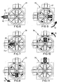
- the baking process in the rack oven 39 is described below with reference to FIG. 6 described to 17 which two alternative continuous baking processes represent for the baked goods batches in the baking trolley 36.
- 6 to 11 show a first such baking process.
- 6 and 7 show like a back-hanging trolley 36 from the import transfer arm 37 into the Partial import baking room 45 is passed. Then the sliding access door 52 closed.
- the associated drive motor 65 is activated so that, as shown in Fig. 7 by arrows 71 a, the baking trolley 36 rotates about its vertical axis in the import partial baking chamber 45.
- the baking trolley 36 in the import part baking room 45 with a predetermined amount of hot air flows around, so that the fermented Baked goods are baked on the baking trays 34.
- the baking trolley 36 While operating the central drive motor 68 the baking trolley 36 does not rotate about its own vertical axis. The Only then does the drive motor 65, which effects this vertical axis rotation, become switched on when the central drive motor 68 was deactivated again.
- the hanging device 61 is designed such that the partitions 44 and the baking trolley 36 synchronously with each other about the vertical axis 43 turn. After the baking process, the 18 to 24 Can take minutes, the sliding exit door 54 is up to this Time was closed, opened and the baking trolley 36 will by means of an export transfer arm 73 which corresponds to the import transfer arm 37 works, removed from the hanging bar 59 and through the outlet opening 54 a removed from the rack oven 39.
- Fig. 12 to 17 show a second baking process, which with the rack oven 39 is possible and with increasing the number of back cycles given the angular velocity of the partition walls 44 simultaneously Baked goods are baked in several baking trolleys 36 can.
- Figs. 12 and 13 correspond to what is the transportation of a first baking trolley 36 concerns, FIGS. 6 and 7. If the baked goods in the first Baking trolley 36 is baked in the import partial baking room 45 with the help of the import transfer arm 37, a second baking trolley 36 provided for import into the import partial baking space 45 and thus initiated another back clock, which partially with the first Back clock overlaps. If, as shown in Fig. 14, the first baking trolley 36 has reached the first transit partial baking space 46 the second baking trolley 36 is introduced into the import partial baking space 45 and the baked goods there are baked on.
- a third baking trolley 36 in the import part baking space 45th introduced as shown in Fig. 15.
- a fourth baking trolley 36 introduced into the import partial baking space 45. If that baked goods there are baked goods in rack oven 39 of a total of four baking trolleys 36 in the context of four each other overlapping backbeats baked at the same time. While the baked goods the first baking trolley 36 is baked, the baked goods of the second and third baking trolley 36 baked through and the baked goods of the fourth baking trolley 36 baked.
- Hot air discharge channels 58 in the partial baking rooms 45 to 48 take place Control of the air circulation around the baking trolleys 36 in such a way that for them different baking situations, i.e. baking, baking and baking, suitable baking conditions are available.
- suitable baking conditions i.e. baking, baking and baking, suitable baking conditions are available.
- the corresponding passage openings when baking only one Allow lower circulating air flow so that baking takes place more gently than the subsequent baking.
- a further baking tray stacking device 77 is provided in which the baking trays 34 must first be stacked before being stored individually back to the transfer device 32 for receiving new fermented Dough pieces are given.
- the baked goods are removed from the baking trays 34 and further Use packed. After packaging, the baked goods can be packed in one Cold room 78 a are stored. Run through the empty baking trays 34 then a cleaning station 78 indicated in FIG. 1, before them in the baking tray stacking device 77, which is of principle construction ago corresponds to the baking tray stacking devices 74 and 35, stacked become.
- the baking system 1 there are separate circuits for the fermentation trays 13 on the one hand and realized for the baking trays 34 on the other hand.
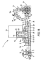
- FIGS. 1 to 17 shows an alternative baking system. Components to those correspond to those already described with reference to FIGS. 1 to 17 have been given the same reference numerals and will not be repeated explained in detail.
- the baking system 1 according to FIG. 18 is more compact than that of 1 to 17, but in principle has the same main components as this on. This greater compactness is such.
- B. achieved in that the Transport route of the knitting plant 10 partly parallel to the transport route in the fermentation device 16 takes place.
- the exit of the fermentation sheets from the knitting plant 10 takes place to the side in the baking system 1 according to FIG. 18 and not, as in the baking system 1 according to FIGS. 1 to 17, in the longitudinal direction of the knitting system 10.
- the fermentation trays 13 are returned after passing through the fermentation device 16 via the fermentation sheet return conveyor belt 33 on a path that is adjacent to the knitting system 10 in alignment with the latter Longitudinal direction takes place. In the baking system 1 according to FIGS. 1 to 17 this return of the fermentation sheets 13 to the knitting plant 10 from the side.
- the space requirement of the compact baking system 1 according to FIG. 18 is approx. 24 mx 8 m.
- Fig. 18 is an expanded fermentation chamber 79, with which an extension of the Proofing time on z. B. four hours is possible, shown in the floor plan.
Landscapes
- Life Sciences & Earth Sciences (AREA)
- Engineering & Computer Science (AREA)
- Food Science & Technology (AREA)
- Manufacturing And Processing Devices For Dough (AREA)
Applications Claiming Priority (2)
| Application Number | Priority Date | Filing Date | Title |
|---|---|---|---|
| DE2002147720 DE10247720A1 (de) | 2002-10-12 | 2002-10-12 | Backsystem sowie Herstellungsverfahren für Backwaren |
| DE10247720 | 2002-10-12 |
Publications (1)
| Publication Number | Publication Date |
|---|---|
| EP1407668A2 true EP1407668A2 (fr) | 2004-04-14 |
Family
ID=32010470
Family Applications (1)
| Application Number | Title | Priority Date | Filing Date |
|---|---|---|---|
| EP20030020233 Withdrawn EP1407668A2 (fr) | 2002-10-12 | 2003-09-06 | Système de cuisson ainsi que procédé de fabrication de produits de cuisson |
Country Status (2)
| Country | Link |
|---|---|
| EP (1) | EP1407668A2 (fr) |
| DE (1) | DE10247720A1 (fr) |
Cited By (2)
| Publication number | Priority date | Publication date | Assignee | Title |
|---|---|---|---|---|
| EP2399460A1 (fr) * | 2010-06-28 | 2011-12-28 | GSF Gesellschaft für System- und Fördertechnik mbH | Dispositif d'alimentation, dispositif de cuisson et procédé de cuisson |
| CN120203094A (zh) * | 2023-12-25 | 2025-06-27 | 胡月平 | 和面发酵一体机及食品自动生产线 |
Families Citing this family (3)
| Publication number | Priority date | Publication date | Assignee | Title |
|---|---|---|---|---|
| DE102009012186B3 (de) * | 2009-02-27 | 2010-09-23 | Wiesheu Gmbh | Vorrichtung und Verfahren zur automatischen Wärmebehandlung von stückförmigen Lebensmittelprodukten |
| DE102016201767B4 (de) * | 2016-02-05 | 2019-11-07 | Daub Backtechnik Gmbh | Modularer Durchlaufwagenofen |
| DE102022134710A1 (de) * | 2022-12-23 | 2024-07-04 | Wanzl GmbH & Co. KGaA | Verfahren, System und Systemkomponente zur Bewerkstelligung des Transfers von Backwaren und/oder Teiglingen |
Citations (1)
| Publication number | Priority date | Publication date | Assignee | Title |
|---|---|---|---|---|
| DE19539856A1 (de) | 1995-10-26 | 1997-04-30 | Poetzscher Carola | Dampfbackofen für Backwaren |
Family Cites Families (3)
| Publication number | Priority date | Publication date | Assignee | Title |
|---|---|---|---|---|
| GB1450336A (en) * | 1974-03-18 | 1976-09-22 | Denholm Ltd Andrew | Bakery oven |
| DE19820279A1 (de) * | 1998-05-07 | 1999-11-11 | Miwe Michael Wenz Gmbh | Vorrichtung zum Transport von Stikkenwagen |
| DE20003240U1 (de) * | 2000-02-22 | 2000-08-03 | Anneliese Mertes Gmbh, 52249 Eschweiler | System zum Wenden von Teiglingen |
-
2002
- 2002-10-12 DE DE2002147720 patent/DE10247720A1/de not_active Withdrawn
-
2003
- 2003-09-06 EP EP20030020233 patent/EP1407668A2/fr not_active Withdrawn
Patent Citations (1)
| Publication number | Priority date | Publication date | Assignee | Title |
|---|---|---|---|---|
| DE19539856A1 (de) | 1995-10-26 | 1997-04-30 | Poetzscher Carola | Dampfbackofen für Backwaren |
Cited By (2)
| Publication number | Priority date | Publication date | Assignee | Title |
|---|---|---|---|---|
| EP2399460A1 (fr) * | 2010-06-28 | 2011-12-28 | GSF Gesellschaft für System- und Fördertechnik mbH | Dispositif d'alimentation, dispositif de cuisson et procédé de cuisson |
| CN120203094A (zh) * | 2023-12-25 | 2025-06-27 | 胡月平 | 和面发酵一体机及食品自动生产线 |
Also Published As
| Publication number | Publication date |
|---|---|
| DE10247720A1 (de) | 2004-04-22 |
Similar Documents
| Publication | Publication Date | Title |
|---|---|---|
| DE69509613T2 (de) | Bäckereiofen zum kontinuierlichen Kochen von Back- oder Konditorwaren oder ähnlichen | |
| EP2706860B1 (fr) | Four muni d'un dispositif d'enlèvement de produit | |
| DE102009026619B4 (de) | Backautomat | |
| EP0445172B1 (fr) | Installation pour le traitement de produits de boulangerie | |
| EP1591011B1 (fr) | Four de cuisson | |
| EP1407668A2 (fr) | Système de cuisson ainsi que procédé de fabrication de produits de cuisson | |
| EP3035803B1 (fr) | Dispositif pour la cuisson de pâtons | |
| EP0827692B1 (fr) | Dispositif et procédé pour transporter une pluralité de plateaux à travers une chambre de fermentation ou four | |
| DE102009012186B3 (de) | Vorrichtung und Verfahren zur automatischen Wärmebehandlung von stückförmigen Lebensmittelprodukten | |
| EP0602352B1 (fr) | Appareil pour la congélation de produits alimentaires | |
| EP2399460A1 (fr) | Dispositif d'alimentation, dispositif de cuisson et procédé de cuisson | |
| DE2121577A1 (de) | Verfahren zum Gären von Backwaren und automatische Endgäranlage | |
| DE102004038879A1 (de) | Vorrichtung zur Wärmebehandlung von Lebensmitteln | |
| EP4118969B1 (fr) | Installation et procédé de fabrication continue de produits de boulangerie | |
| DE10228500A1 (de) | Vorrichtung zur automatischen Wärmebehandlung von stückförmigen Lebensmitteln sowie Ofen hierzu | |
| EP0430938B1 (fr) | Four de boulangerie | |
| AT376106B (de) | Backofen | |
| EP0813366B1 (fr) | Four de boulangerie | |
| EP4559315A2 (fr) | Dispositif de transfert pour charger et/ou décharger une unité de traitement d'aliments | |
| DE3225813A1 (de) | Backofen | |
| EP0814673B1 (fr) | Procede et dispositif de maturation de lots de denrees alimentaires | |
| DE4215146A1 (de) | Vorrichtung zum Garen von Teigportionen | |
| EP0948261B1 (fr) | Procede de traitement de produits a base d'amidon | |
| DE102017215202A1 (de) | Kühlsystem zur Kühlung von frisch gebackenen, abzukühlenden Gebäckstücken sowie Backanlage mit mindestens einem derartigen Kühlsystem | |
| EP0746983A2 (fr) | Chambre de repos avec un dispositif de transport des supports sans chaînes et méthode d'opération |
Legal Events
| Date | Code | Title | Description |
|---|---|---|---|
| PUAI | Public reference made under article 153(3) epc to a published international application that has entered the european phase |
Free format text: ORIGINAL CODE: 0009012 |
|
| AK | Designated contracting states |
Kind code of ref document: A2 Designated state(s): AT BE BG CH CY CZ DE DK EE ES FI FR GB GR HU IE IT LI LU MC NL PT RO SE SI SK TR |
|
| AX | Request for extension of the european patent |
Extension state: AL LT LV MK |
|
| STAA | Information on the status of an ep patent application or granted ep patent |
Free format text: STATUS: THE APPLICATION HAS BEEN WITHDRAWN |
|
| 18W | Application withdrawn |
Effective date: 20051010 |