EP1407696A2 - Regalsystem - Google Patents
Regalsystem Download PDFInfo
- Publication number
- EP1407696A2 EP1407696A2 EP03021902A EP03021902A EP1407696A2 EP 1407696 A2 EP1407696 A2 EP 1407696A2 EP 03021902 A EP03021902 A EP 03021902A EP 03021902 A EP03021902 A EP 03021902A EP 1407696 A2 EP1407696 A2 EP 1407696A2
- Authority
- EP
- European Patent Office
- Prior art keywords
- column
- foot member
- flaps
- slot
- foot
- Prior art date
- Legal status (The legal status is an assumption and is not a legal conclusion. Google has not performed a legal analysis and makes no representation as to the accuracy of the status listed.)
- Withdrawn
Links
- 238000003466 welding Methods 0.000 claims abstract description 8
- 238000005304 joining Methods 0.000 claims description 19
- 239000002184 metal Substances 0.000 claims description 6
- 239000000463 material Substances 0.000 claims description 4
- 238000003825 pressing Methods 0.000 claims description 3
- 230000009467 reduction Effects 0.000 claims description 3
- 238000006073 displacement reaction Methods 0.000 claims 1
- 238000004519 manufacturing process Methods 0.000 abstract description 2
- 210000002105 tongue Anatomy 0.000 description 27
- 230000008901 benefit Effects 0.000 description 2
- 230000000717 retained effect Effects 0.000 description 2
- 238000004873 anchoring Methods 0.000 description 1
- 230000008859 change Effects 0.000 description 1
- 238000010276 construction Methods 0.000 description 1
- 230000007246 mechanism Effects 0.000 description 1
- 230000007704 transition Effects 0.000 description 1
Images


Classifications
-
- A—HUMAN NECESSITIES
- A47—FURNITURE; DOMESTIC ARTICLES OR APPLIANCES; COFFEE MILLS; SPICE MILLS; SUCTION CLEANERS IN GENERAL
- A47B—TABLES; DESKS; OFFICE FURNITURE; CABINETS; DRAWERS; GENERAL DETAILS OF FURNITURE
- A47B91/00—Feet for furniture in general
- A47B91/16—Self-levelling legs
-
- A—HUMAN NECESSITIES
- A47—FURNITURE; DOMESTIC ARTICLES OR APPLIANCES; COFFEE MILLS; SPICE MILLS; SUCTION CLEANERS IN GENERAL
- A47F—SPECIAL FURNITURE, FITTINGS, OR ACCESSORIES FOR SHOPS, STOREHOUSES, BARS, RESTAURANTS OR THE LIKE; PAYING COUNTERS
- A47F5/00—Show stands, hangers, or shelves characterised by their constructional features
- A47F5/0018—Display racks with shelves or receptables
Definitions
- the present invention concerns a shelf system, preferably for displaying articles in shops, department stores, supermarkets and warehouses, of the kind including vertically upright tubular columns standing from a base, where at least one side, and preferably two opposite sides include first apertures extending in the longitudinal direction of the columns and running in parallel for mounting supports projecting from the columns and between which shelves are disposed, where the columns are supported by at least one releasably attached foot member projecting from the lower end of the column and at the same side of the column to which the shelf supports are projecting, including adjustable legs, and where one end side of the adjustable legs include at least one first upper projecting lock tongue and a second lower lock tongue interacting with a first upper and second lower aperture at the column side.
- a similar shelf system is known from EP 1 075 809 A1 in which is indicated a foot member for the shelf system on which on the central rail, fittings with adjustable legs may be mounted.
- the foot member is made of a plate and may be connected to the fitting with the adjustable leg.
- the foot is furthermore provided with an adjustable leg.
- EP A 1 106 119 describes a foot member for a pipe in a shelf system where in the centre axis of the pipe there is disposed an adjustable leg, and at the side of the pipe there is fitted a foot member.
- the foot member is made of a four-sided pipe section.
- the document also indicated different embodiments where the central pipe may be finished in different ways by ends/transition pieces at which foot members may be mounted at one or both sides of the pipe.
- a foot member for a shelf system with a central rail where the rail is provided with an adjustable rail leg.
- the rail is provided at both sides with a cutout in which a foot member is attached.
- the foot member is designed so that at one end it has one or more projections that engage the cutouts in the rail, and at the opposite end adjustable legs are provided.
- the said adjustable leg is adjustable as it is adapted for mounting with a pull arrangement incorporated in the plate section of the foot member.
- the foot member is made of a plate with edges so that it has an I-shaped cross-section.
- the said plate furthermore includes welded retainer flanges at the sides with the purpose of retaining the foot member in the rail.
- a foot member with significant strength properties as the two welded laterally reversed and identically profiled plate pieces together represent a not insignificant moment of resistance for absorbing the moment exerted on the columns in connection with the load on the shelves mounted on the column.
- the foot member is furthermore solidly secured to the column by using the U-shaped locking profile having its flaps inserted into the cavity of the column in such a way that these are accommodated in a slot in the lower part of a locking tongue that project from the side edge of the foot member facing the column.
- the flaps of the U-shaped locking member blocks against withdrawal of the locking tongue of the foot member, as the said flap is disposed between the locking tongue and the internal column wall.
- the construction is also adapted so that the same opposite flap of the U-shaped profile may lock a second foot member, the locking tongue of which being inserted into apertures adapted therefore at the opposite side of the column.
- the slot in the second lower locking tongue with at least one projection at one or at both sides, there is formed a minor reduction of the width of the slot, however allowing pressing in of one of the flaps of the U-shaped locking member in the slot to the bottom of the slot, there is achieved the advantage that the U-shaped locking member is retained in its engagement with the foot member, which means that one may move the columns at will without risking loss of the foot member.
- the U-shaped locking member is furthermore designed so that the bottom of the U-shaped locking member is wider than the flaps and has a width at least corresponding to the external width/diameter of the column. This implies that the locking member also serves as support for the column.
- the foot member of the shelf system is formed by two laterally reversed, identically profiled plate pieces extending in parallel that over a length have mutually facing sides in mutual contact, so that the plates in this area can be joined by e.g. spot weldings.
- the profiling of these plates implies that in conjunction these form an upper U-shaped profile over the joining area and a lower inverted U-shaped profile under the joining area.
- the upper profile is furthermore provided with a parallel offset. It is indicated that the first upper locking tongues are disposed in the ends of the flaps in the upper U-shaped profile, and the lower locking tongues are placed in the ends of the lower inverted U-profile under the joining area. It is furthermore noted that the lower locking tongues are considerably broader and stronger in their structure than the upper locking tongue. This is due to the fact that the moment and the pull in the foot member on this spot is considerable due to the moment from the column.
- the lower inverted U-shaped profile has furthermore cutouts or slots in the flaps close to the end edge of the foot member.
- This cutout is intended for receiving a piece, preferably of metal or similar suited material, in which is provided a threaded hole for receiving one end of a threaded spindle, the other end of which including an adjustable leg.
- the free end of the threaded spindle is furthermore formed with a non-circular recess for receiving a another part of a tool.
- adjustment of the adjustable leg may be performed by inserting tools from the front edge of the foot member between the flaps in the U-profile.
- the foot member may furthermore have a second slit-shaped aperture oriented transversely of the longitudinal axis of the foot member, the centre line of which coinciding with the centre of the first slit-shaped apertures and extending at least from the bottom of the upper, mainly U-shaped profile above the joining area between the plate pieces to the bottom of the lower, inverted U-shaped profile under the joining area.
- a second slit-shaped aperture oriented transversely of the longitudinal axis of the foot member, the centre line of which coinciding with the centre of the first slit-shaped apertures and extending at least from the bottom of the upper, mainly U-shaped profile above the joining area between the plate pieces to the bottom of the lower, inverted U-shaped profile under the joining area.
- the upward facing side edge of the foot member nearest the column may include a slot for arresting reception of downwards projecting parts of the shelf placed on the foot member.
- the upwards facing side edge of the foot member may include a recessed area in which parts projecting from the underside of the said shelves may be received.
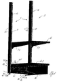
- Fig. 1 is shown an embodiment of a section for a shelf system 2 that include a tubular column standing vertically from a base 4, where at least one side 8 of the column include first apertures 12 extending in parallel oriented in longitudinal direction of the column for mounting these projecting supports 14, where between shelves 16 are provided.
- the columns 6 are supported by at least one releasably attached foot member projecting from the lower end of the column and the same side of the column 6 to which the supports 14 for shelves 16 project, where the foot member includes adjustable legs 22.
- One end side of the foot member includes at least one first upper projecting locking tongue 30 and a second lower locking tongue 32 interacting with a first upper aperture 12 and a second lower aperture 28 in the column side 8.
- Fig. 2 a perspective view of the column mounted with a foot member 20.
- Fig. 3 a side 8 including parallel rows of apertures 12 for mounting shelf supports 14. At the lower part 18 of the column is seen the mounting holes 26 for the first upper locking tongues 30 in the foot member 20 and under these, longer slots 28 for accommodating the other, lower locking tongues 32.
- Fig. 4 is a side view of a column
- Fig. 5 is showing a cross-section of an embodiment of the column as shown in Fig. 3.
- Fig. 6 a side view of an embodiment of a foot member 20.
- the foot member 20 consists of two laterally reversed, identical, profiled plate pieces 34, 34' (see Fig. 7) extending in parallel that in a joining area 38, where the mutually facing sides 36, 36' of the plates are in contact with each other, are preferably joined by spot welding.
- the profile curves of the plate pieces 34, 34' implies that an upper U-shaped section 58 is formed above the joining area 38, and a lower inverted U-shaped profile 60 is formed under the joining area 38.
- the plate pieces at the end opposite the locking tongues 30, 32 at the underside include an aperture 74 intended for receiving a metal piece 76, cf. Fig. 11, the metal piece having a threaded hole 78 for receiving a threaded spindle 80 in the end of which is provided an adjustable leg 82.
- the threaded spindle 80 includes an non-circular recess 84 at the upper end for receiving a tool so that it will be possible to turn the threaded spindle 80 and thereby perform a level adjustment of the front end of the foot member.
- a slit-shaped slot 86 the longitudinal axis 90 of which is oriented transversely of the longitudinal axis 88 of the foot member, cf. Fig. 10.
- the said slot 86 will facilitate the access to the non-circular recess 84 at the end of the threaded spindle 80 with a tool, whereby the tool, whereby the work with adjusting the said adjustable leg will be significantly eased, as this may be done either from the front edge of the foot member 20 or from the side of same.
- the foot member includes an upper locking tongue 30 and, compared with the latter tongue, a considerably stronger locking tongue 32 including a slit 43 having an aperture oriented towards the lower edge 97 of the foot member.
- the side 41 of the slot 43 facing the internal side 48 of the column 6 at the underside of the locking tongue 32 is disposed at a distance from side of the foot member 24 facing column 6, corresponding to at least the material thickness of the column, whereby space is made for accommodating the column wall between the underside of the foot member and the slot opening, as outlined in Fig. 12.
- a U-shaped locking member 40 belongs to the shelf, as shown in details in Fig. 13.
- the U-shaped locking member has a bottom 50 that include a threaded hole 52, and the bottom also include flaps 42, 44 standing up from it and having a width less than the width of the bottom 50.
- Figs. 8, 9, 10, 11 and 12 is seen how the U-shaped locking member is used in connection with fastening the foot member 20 to the columns 6.
- Fig. 8 is thus a side view of the column provided with the foot member
- Fig. 9 is a front view of the same
- Fig. 10 is a top view of the column shown in Fig. 8.
- the U-shaped locking member 40 for fastening the foot member to the column is shown in Fig. 11.
- the flaps 42, 44 are, as it particularly appears from Fig. 12, a detail of Fig. 11 made in the cavity 46 of the column, so that the flap 44 of the U-shaped locking member is inserted into the slot 43 at the underside of the locking tongue 32, and the said flap 44 is furthermore in contact with the internal column wall 48.
- the U-shaped locking member includes an adjustable leg 56 on a threaded spindle 54 which is inserted in the threaded hole 52 in the bottom 50 of the U-shaped locking member.
- the slot 43 has a projection 45 at one side 41, forming a minor reduction of the width of the slot, though allowing pressing in of one of the flaps 42, 44 of the U-shaped locking member 40 in the slot 43 to the bottom 49 of the slot, as it appears from Fig. 12.
- the U-shaped locking member is retained in its engagement with the foot member, irrespectively whether the column is lifted completely free of the base 4 on which it is placed.
- the foot member includes in the upwards facing side edge close to the column side 8 a slit-shaped slot 98 for receiving downwards projecting parts of a shelf 102 placed upon the foot member 20.
- the foot member is furthermore adapted for supporting wire shelves or wooden shelves, as the upper side 96 of the foot member 20 has a recessed area 104 for receiving parts projecting downwards from wooden shelves and wire shelves.
- Fig. 7 is a cross-sectional view of a foot member
- a profile curving of the plate parts 34, 34' has been made, so that the distance between the flaps 62, 62' of the U-profile 58 over the joining area 38 is wider than the distance between the flaps 64, 64' in the inverted U-profile under the joining area 38 of the plate parts 34, 34'.
- the flaps are, however, by a parallel offset 68, 68' brought in so that the free ends 66, 66' are disposed with mutual spacing corresponding to the distance between the flaps 64, 64' in the inverted U-section 60.
- the U-profile 58 there will achieved a significant increase of the moment of resistance that the foot member represents and can absorb.
- a shelf system with foot member according to the invention may assume other embodiments than those indicated and described above.
- the profiling of the plate pieces 34, 34' may be different with the purpose of attaining a further increased moment of resistance, but this does not change the inventive aspect constituted in that a fully usable foot member is made by joining two identically profiled but laterally reversed plates, as indicated in the claim, and are secured in the column member with a U-shaped locking member which is inserted between the locking tongue and the internal column wall.
Landscapes
- Assembled Shelves (AREA)
Applications Claiming Priority (2)
| Application Number | Priority Date | Filing Date | Title |
|---|---|---|---|
| DK200201499 | 2002-10-07 | ||
| DK200201499A DK174955B1 (da) | 2002-10-07 | 2002-10-07 | Reolsystem |
Publications (2)
| Publication Number | Publication Date |
|---|---|
| EP1407696A2 true EP1407696A2 (de) | 2004-04-14 |
| EP1407696A3 EP1407696A3 (de) | 2005-01-12 |
Family
ID=31984974
Family Applications (1)
| Application Number | Title | Priority Date | Filing Date |
|---|---|---|---|
| EP03021902A Withdrawn EP1407696A3 (de) | 2002-10-07 | 2003-09-29 | Regalsystem |
Country Status (2)
| Country | Link |
|---|---|
| EP (1) | EP1407696A3 (de) |
| DK (1) | DK174955B1 (de) |
Cited By (1)
| Publication number | Priority date | Publication date | Assignee | Title |
|---|---|---|---|---|
| US10231556B2 (en) | 2012-11-20 | 2019-03-19 | Ccl Label, Inc. | Wall mount organization system |
Citations (3)
| Publication number | Priority date | Publication date | Assignee | Title |
|---|---|---|---|---|
| US5433327A (en) | 1993-07-26 | 1995-07-18 | Knape & Vogt Canada, Inc. | Merchandise display rack with reinforced bases |
| EP1075809A1 (de) | 1999-08-10 | 2001-02-14 | Tegometall (International) AG | Regalständer |
| EP1106119A1 (de) | 1999-12-03 | 2001-06-13 | Tegometall (International) AG | Fussteil für Rundsäulen-Regalständer |
Family Cites Families (5)
| Publication number | Priority date | Publication date | Assignee | Title |
|---|---|---|---|---|
| AT299482B (de) * | 1970-02-21 | 1972-06-26 | Linde Ag | Fußstütze für Ladenmöbel |
| DE3028552A1 (de) * | 1980-07-28 | 1982-02-25 | Tegometall Rudolf Bohnacker, 7482 Krauchenwies | Winkelfoermige trageinheit fuer stehende regale |
| GB2223816B (en) * | 1988-10-04 | 1992-10-14 | Baxter Fell Northfleet Limited | Support means for use in a display system |
| GB9710079D0 (en) * | 1997-05-20 | 1997-07-09 | B Mat Limited | Shelving |
| DE20005408U1 (de) * | 2000-03-22 | 2000-05-18 | Nedcon Magazijninrichting B.V., Doetinchem | Verankerungssystem zur höhenjustierbaren Verankerung einer vertikalen Regalstütze im Untergrund |
-
2002
- 2002-10-07 DK DK200201499A patent/DK174955B1/da not_active IP Right Cessation
-
2003
- 2003-09-29 EP EP03021902A patent/EP1407696A3/de not_active Withdrawn
Patent Citations (3)
| Publication number | Priority date | Publication date | Assignee | Title |
|---|---|---|---|---|
| US5433327A (en) | 1993-07-26 | 1995-07-18 | Knape & Vogt Canada, Inc. | Merchandise display rack with reinforced bases |
| EP1075809A1 (de) | 1999-08-10 | 2001-02-14 | Tegometall (International) AG | Regalständer |
| EP1106119A1 (de) | 1999-12-03 | 2001-06-13 | Tegometall (International) AG | Fussteil für Rundsäulen-Regalständer |
Cited By (1)
| Publication number | Priority date | Publication date | Assignee | Title |
|---|---|---|---|---|
| US10231556B2 (en) | 2012-11-20 | 2019-03-19 | Ccl Label, Inc. | Wall mount organization system |
Also Published As
| Publication number | Publication date |
|---|---|
| DK174955B1 (da) | 2004-03-22 |
| EP1407696A3 (de) | 2005-01-12 |
Similar Documents
| Publication | Publication Date | Title |
|---|---|---|
| US4549665A (en) | Shelf assembly | |
| US11197543B2 (en) | Cantilever shelving system | |
| US20010019235A1 (en) | Pull-out guide for drawers | |
| US20120067838A1 (en) | Industrial frame rack support assembly | |
| EP3691494B1 (de) | Modularer aufbau für regale | |
| US20010004064A1 (en) | Display stand module | |
| EP3964671B1 (de) | Modulares plattformsystem und montageverfahren | |
| EP3700391A1 (de) | Wandmontiertes konfigurierbares speichersystem | |
| US12575676B2 (en) | Shelving unit tie bar | |
| US20040045921A1 (en) | Adjustable shelf storage system | |
| US4218789A (en) | Bed stand | |
| US4231298A (en) | Shelving system | |
| EP1407696A2 (de) | Regalsystem | |
| US6036034A (en) | Modular display stand assembly | |
| WO2001010269A1 (en) | Modular display stand assembly | |
| CA1187453A (en) | Storage systems | |
| US7407152B2 (en) | Fencing system and post insert for use therewith | |
| EP1672228B1 (de) | Vorrichtung zum Verbinden von Rahmenteilen | |
| US4226193A (en) | Shelf assembly | |
| EP1207766B1 (de) | Kragarmregal | |
| CZ297567B6 (cs) | Regál | |
| JP3485009B2 (ja) | 間口可変型流動棚 | |
| JPH0311A (ja) | ワゴン | |
| EP2664256B1 (de) | Verstärktes metallisches Regal für modulare Regalstruktur | |
| PL196137B1 (pl) | Stojak regałowy |
Legal Events
| Date | Code | Title | Description |
|---|---|---|---|
| PUAI | Public reference made under article 153(3) epc to a published international application that has entered the european phase |
Free format text: ORIGINAL CODE: 0009012 |
|
| AK | Designated contracting states |
Kind code of ref document: A2 Designated state(s): AT BE BG CH CY CZ DE DK EE ES FI FR GB GR HU IE IT LI LU MC NL PT RO SE SI SK TR |
|
| AX | Request for extension of the european patent |
Extension state: AL LT LV MK |
|
| PUAL | Search report despatched |
Free format text: ORIGINAL CODE: 0009013 |
|
| AK | Designated contracting states |
Kind code of ref document: A3 Designated state(s): AT BE BG CH CY CZ DE DK EE ES FI FR GB GR HU IE IT LI LU MC NL PT RO SE SI SK TR |
|
| AX | Request for extension of the european patent |
Extension state: AL LT LV MK |
|
| AKX | Designation fees paid | ||
| REG | Reference to a national code |
Ref country code: DE Ref legal event code: 8566 |
|
| STAA | Information on the status of an ep patent application or granted ep patent |
Free format text: STATUS: THE APPLICATION IS DEEMED TO BE WITHDRAWN |
|
| 18D | Application deemed to be withdrawn |
Effective date: 20050713 |