EP1407852A2 - Verfahren zum Bearbeiten von axialen Nuten für Schaufeln in Turbinenscheiben für Strahltriebwerke - Google Patents
Verfahren zum Bearbeiten von axialen Nuten für Schaufeln in Turbinenscheiben für Strahltriebwerke Download PDFInfo
- Publication number
- EP1407852A2 EP1407852A2 EP20030256289 EP03256289A EP1407852A2 EP 1407852 A2 EP1407852 A2 EP 1407852A2 EP 20030256289 EP20030256289 EP 20030256289 EP 03256289 A EP03256289 A EP 03256289A EP 1407852 A2 EP1407852 A2 EP 1407852A2
- Authority
- EP
- European Patent Office
- Prior art keywords
- slot
- finished
- machining
- process according
- quill
- Prior art date
- Legal status (The legal status is an assumption and is not a legal conclusion. Google has not performed a legal analysis and makes no representation as to the accuracy of the status listed.)
- Granted
Links
Images
Classifications
-
- B—PERFORMING OPERATIONS; TRANSPORTING
- B23—MACHINE TOOLS; METAL-WORKING NOT OTHERWISE PROVIDED FOR
- B23C—MILLING
- B23C3/00—Milling particular work; Special milling operations; Machines therefor
- B23C3/28—Grooving workpieces
- B23C3/30—Milling straight grooves, e.g. keyways
-
- B—PERFORMING OPERATIONS; TRANSPORTING
- B21—MECHANICAL METAL-WORKING WITHOUT ESSENTIALLY REMOVING MATERIAL; PUNCHING METAL
- B21D—WORKING OR PROCESSING OF SHEET METAL OR METAL TUBES, RODS OR PROFILES WITHOUT ESSENTIALLY REMOVING MATERIAL; PUNCHING METAL
- B21D28/00—Shaping by press-cutting; Perforating
- B21D28/24—Perforating, i.e. punching holes
- B21D28/28—Perforating, i.e. punching holes in tubes or other hollow bodies
-
- B—PERFORMING OPERATIONS; TRANSPORTING
- B23—MACHINE TOOLS; METAL-WORKING NOT OTHERWISE PROVIDED FOR
- B23P—METAL-WORKING NOT OTHERWISE PROVIDED FOR; COMBINED OPERATIONS; UNIVERSAL MACHINE TOOLS
- B23P13/00—Making metal objects by operations essentially involving machining but not covered by a single other subclass
- B23P13/02—Making metal objects by operations essentially involving machining but not covered by a single other subclass in which only the machining operations are important
-
- B—PERFORMING OPERATIONS; TRANSPORTING
- B23—MACHINE TOOLS; METAL-WORKING NOT OTHERWISE PROVIDED FOR
- B23P—METAL-WORKING NOT OTHERWISE PROVIDED FOR; COMBINED OPERATIONS; UNIVERSAL MACHINE TOOLS
- B23P15/00—Making specific metal objects by operations not covered by a single other subclass or a group in this subclass
- B23P15/006—Making specific metal objects by operations not covered by a single other subclass or a group in this subclass turbine wheels
-
- B—PERFORMING OPERATIONS; TRANSPORTING
- B24—GRINDING; POLISHING
- B24B—MACHINES, DEVICES, OR PROCESSES FOR GRINDING OR POLISHING; DRESSING OR CONDITIONING OF ABRADING SURFACES; FEEDING OF GRINDING, POLISHING, OR LAPPING AGENTS
- B24B1/00—Processes of grinding or polishing; Use of auxiliary equipment in connection with such processes
-
- B—PERFORMING OPERATIONS; TRANSPORTING
- B24—GRINDING; POLISHING
- B24B—MACHINES, DEVICES, OR PROCESSES FOR GRINDING OR POLISHING; DRESSING OR CONDITIONING OF ABRADING SURFACES; FEEDING OF GRINDING, POLISHING, OR LAPPING AGENTS
- B24B19/00—Single-purpose machines or devices for particular grinding operations not covered by any other main group
- B24B19/02—Single-purpose machines or devices for particular grinding operations not covered by any other main group for grinding grooves, e.g. on shafts, in casings, in tubes, homokinetic joint elements
-
- B—PERFORMING OPERATIONS; TRANSPORTING
- B24—GRINDING; POLISHING
- B24B—MACHINES, DEVICES, OR PROCESSES FOR GRINDING OR POLISHING; DRESSING OR CONDITIONING OF ABRADING SURFACES; FEEDING OF GRINDING, POLISHING, OR LAPPING AGENTS
- B24B19/00—Single-purpose machines or devices for particular grinding operations not covered by any other main group
- B24B19/14—Single-purpose machines or devices for particular grinding operations not covered by any other main group for grinding turbine blades, propeller blades or the like
-
- F—MECHANICAL ENGINEERING; LIGHTING; HEATING; WEAPONS; BLASTING
- F01—MACHINES OR ENGINES IN GENERAL; ENGINE PLANTS IN GENERAL; STEAM ENGINES
- F01D—NON-POSITIVE DISPLACEMENT MACHINES OR ENGINES, e.g. STEAM TURBINES
- F01D5/00—Blades; Blade-carrying members; Heating, heat-insulating, cooling or antivibration means on the blades or the members
- F01D5/30—Fixing blades to rotors; Blade roots ; Blade spacers
- F01D5/3007—Fixing blades to rotors; Blade roots ; Blade spacers of axial insertion type
-
- B—PERFORMING OPERATIONS; TRANSPORTING
- B23—MACHINE TOOLS; METAL-WORKING NOT OTHERWISE PROVIDED FOR
- B23C—MILLING
- B23C2220/00—Details of milling processes
- B23C2220/36—Production of grooves
- B23C2220/366—Turbine blade grooves
-
- F—MECHANICAL ENGINEERING; LIGHTING; HEATING; WEAPONS; BLASTING
- F05—INDEXING SCHEMES RELATING TO ENGINES OR PUMPS IN VARIOUS SUBCLASSES OF CLASSES F01-F04
- F05D—INDEXING SCHEME FOR ASPECTS RELATING TO NON-POSITIVE-DISPLACEMENT MACHINES OR ENGINES, GAS-TURBINES OR JET-PROPULSION PLANTS
- F05D2230/00—Manufacture
- F05D2230/10—Manufacture by removing material
-
- Y—GENERAL TAGGING OF NEW TECHNOLOGICAL DEVELOPMENTS; GENERAL TAGGING OF CROSS-SECTIONAL TECHNOLOGIES SPANNING OVER SEVERAL SECTIONS OF THE IPC; TECHNICAL SUBJECTS COVERED BY FORMER USPC CROSS-REFERENCE ART COLLECTIONS [XRACs] AND DIGESTS
- Y10—TECHNICAL SUBJECTS COVERED BY FORMER USPC
- Y10T—TECHNICAL SUBJECTS COVERED BY FORMER US CLASSIFICATION
- Y10T29/00—Metal working
- Y10T29/47—Burnishing
-
- Y—GENERAL TAGGING OF NEW TECHNOLOGICAL DEVELOPMENTS; GENERAL TAGGING OF CROSS-SECTIONAL TECHNOLOGIES SPANNING OVER SEVERAL SECTIONS OF THE IPC; TECHNICAL SUBJECTS COVERED BY FORMER USPC CROSS-REFERENCE ART COLLECTIONS [XRACs] AND DIGESTS
- Y10—TECHNICAL SUBJECTS COVERED BY FORMER USPC
- Y10T—TECHNICAL SUBJECTS COVERED BY FORMER US CLASSIFICATION
- Y10T29/00—Metal working
- Y10T29/49—Method of mechanical manufacture
- Y10T29/49316—Impeller making
- Y10T29/4932—Turbomachine making
- Y10T29/49321—Assembling individual fluid flow interacting members, e.g., blades, vanes, buckets, on rotary support member
-
- Y—GENERAL TAGGING OF NEW TECHNOLOGICAL DEVELOPMENTS; GENERAL TAGGING OF CROSS-SECTIONAL TECHNOLOGIES SPANNING OVER SEVERAL SECTIONS OF THE IPC; TECHNICAL SUBJECTS COVERED BY FORMER USPC CROSS-REFERENCE ART COLLECTIONS [XRACs] AND DIGESTS
- Y10—TECHNICAL SUBJECTS COVERED BY FORMER USPC
- Y10T—TECHNICAL SUBJECTS COVERED BY FORMER US CLASSIFICATION
- Y10T29/00—Metal working
- Y10T29/49—Method of mechanical manufacture
- Y10T29/49995—Shaping one-piece blank by removing material
- Y10T29/49996—Successive distinct removal operations
Definitions
- the present invention relates to a process for machining axial blade slots in turbine disks for jet engines.
- Retention slots are a design feature of turbine disks.
- the slots are used to hold or retain turbine blades around the periphery of the disk.
- Current practice in the aerospace industry is to machine these slots into the disk by use of a broaching machine, which is a linear cutting machine that drives successively larger cutters through the disk slot, with the final cutters having the fir tree or other appropriate shape of the finished slot.
- a broaching machine which is a linear cutting machine that drives successively larger cutters through the disk slot, with the final cutters having the fir tree or other appropriate shape of the finished slot.
- U.S. Patent No. 5,430,936 to Yadzik, Jr. et al. Broaching presents a number of issues, including costly cutter tools, very long tooling lead-time, very long tooling set-ups, and a very large single-purpose machine requiring a special concrete base and other infrastructure to support it.
- U.S. Patent No. 5,330,326 to Kuehne et al Another method for producing profiled parts is illustrated in U.S. Patent No. 5,330,326 to Kuehne et al.
- the method involves pre-shaping and finish grinding a blank in one chucking position with at least one profiled grinding wheel.
- the blank is translated and rotated relative to the at least one profiled grinding wheel during the pre-shaping step for giving the blank approximately a desired profile.
- the finished grinding step is performed at least partially after the pre-shaping step for smoothing surfaces and producing the final profile.
- the Kuehne et al. method may be used for external surfaces, such as the cutting of blades, and not internal surfaces. Thus, Kuehne et al.'s method is not applicable to the creation of internal slots.
- a process for machining axial blade slots in a turbine disk broadly comprises the steps of providing a turbine disk, forming a roughened slot having a plurality of joined rectangular areas in the turbine disk, and machining the roughened slot into a finished slot.
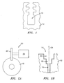
- the present invention relates to a process for machining axial blade slots, such as those designated by the reference numeral 10 in FIG. 1, in turbine disks 12 for use in jet engines.
- the process initially involves the step of providing a blank turbine disk 12.
- the blank turbine disk 12 may be formed from a nickel based superalloy, a titanium based superalloy, steel, or another suitable material.
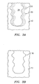
- the next step in the process is to form a series of roughened slots 14 in the blank disk 12.
- Each of the roughened slots 14 has a plurality of joined rectangular areas such as 2, 3, or 4 joined rectangular areas.
- FIG. 2B illustrates a roughened slot having three rectangular areas 16, 18, and 20.
- the rectangular areas 16, 18 and 20 may be formed using a grinding machine 22 such as that shown in FIG. 2A and a series of superabrasive grinding wheels 24 connected to a spindle 26.
- a superabrasive grinding wheel is a class of wheels where the abrasive material is diamond or cubic boron nitride.
- a first superabrasive grinding wheel 24 having a first thickness is used to form the rectangular area 20.
- a second superabrasive grinding wheel having a second thickness less than the first thickness is connected to the spindle 26 and used to form the rectangular area 18.
- a third superabrasive grinding wheel having a third thickness less than the second thickness is connected to the spindle 26 and used to form the rectangular area 16.
- Each of the grinding wheels preferably has a diameter in the range of six inches to twelve inches (152-304 mm), is formed from tool steel, and preferably has a single layer carbon boron nitride thereon to form the wheel grinding surfaces. The carbon boron nitride may be electroplated or brazed to the underlying tool steel.
- a coolant such as an oil coolant, may be used to reduce excessive heat.
- a finished slot 30 is formed.
- the finished slot 30 may be formed using one of two different processes.
- a first process the finished slot 30 is formed in two steps using two quills having a diameter less than a width W of the finished slot and a profile identical to the profile of the finished slot.
- a semi-finished slot 32 is formed using a first quill 36.
- the first quill is offset in a first direction relative to the centerline 34 of the roughened slot 14 and then offset in a second direction opposite to the first direction.
- the first quill is then removed and a second quill is used to form the finished slot 30.
- the second quill is also offset in one direction relative to the centerline 34 to finish a first side and then offset in a second direction, opposed to the first direction, to finish a second side.
- each of the quills has a diameter in the range of 0.020 to 0.030 inches (0.5-0.76 mm) less than the width of the finished slot. If desired, a single quill could be used to form the semi-finished and finished slots instead of two different quills.
- the finished slot 30 is formed using two quills.
- the first quill has a dimension slightly less than that of the finished slot 30.
- the second quill has the same dimension as the finished slot 30.
- the first quill is aligned with the centerline 34 of the roughened slot and used to form a semi-finish slot in a single pass and the second quill is aligned with the centerline of the semi-finished slot to form the finish cut in one pass, cutting both sides of the slot simultaneously.
- Each of the quills used to perform the cuts has a single layer of carbon boron nitride electroplated or brazed on a tool steel form.
- a coolant such as an oil coolant, may be used to avoid excessive heat.
- the finishing quill should have proper abrasive grit size and distribution to form slot walls with a roughness under 65 Ra.
- a semi-finishing quill will have a grit size in the range of 60 to 120, while the finishing quill will have a grit size in the range of 170 to 340.
Landscapes
- Engineering & Computer Science (AREA)
- Mechanical Engineering (AREA)
- General Engineering & Computer Science (AREA)
- Turbine Rotor Nozzle Sealing (AREA)
- Electrical Discharge Machining, Electrochemical Machining, And Combined Machining (AREA)
- Grinding And Polishing Of Tertiary Curved Surfaces And Surfaces With Complex Shapes (AREA)
Applications Claiming Priority (2)
| Application Number | Priority Date | Filing Date | Title |
|---|---|---|---|
| US266021 | 2002-10-07 | ||
| US10/266,021 US6883234B2 (en) | 2002-10-07 | 2002-10-07 | Process for machining axial blade slots in turbine disks for jet engines |
Publications (3)
| Publication Number | Publication Date |
|---|---|
| EP1407852A2 true EP1407852A2 (de) | 2004-04-14 |
| EP1407852A3 EP1407852A3 (de) | 2007-02-28 |
| EP1407852B1 EP1407852B1 (de) | 2010-12-22 |
Family
ID=32030338
Family Applications (1)
| Application Number | Title | Priority Date | Filing Date |
|---|---|---|---|
| EP03256289A Expired - Lifetime EP1407852B1 (de) | 2002-10-07 | 2003-10-06 | Verfahren zum Bearbeiten von axialen Nuten für Schaufeln in Turbinenscheiben für Strahltriebwerke |
Country Status (5)
| Country | Link |
|---|---|
| US (2) | US6883234B2 (de) |
| EP (1) | EP1407852B1 (de) |
| JP (1) | JP2004132375A (de) |
| KR (1) | KR100558797B1 (de) |
| DE (1) | DE60335437D1 (de) |
Cited By (7)
| Publication number | Priority date | Publication date | Assignee | Title |
|---|---|---|---|---|
| WO2007096295A1 (en) * | 2006-02-22 | 2007-08-30 | Siemens Aktiengesellschaft | Cup shaped grinding wheel, in particular for turbine root slot grinding |
| WO2009109422A1 (de) * | 2008-03-03 | 2009-09-11 | Alstom Technology Ltd. | Vorrichtung zur nachbearbeitung von befestigungsnuten zur aufnahme einer beschaufelung einer gas- und/oder dampfturbinenanlage |
| US7708619B2 (en) | 2006-05-23 | 2010-05-04 | Saint-Gobain Abrasives, Inc. | Method for grinding complex shapes |
| CN103273404A (zh) * | 2013-06-06 | 2013-09-04 | 萍乡市德博科技发展有限公司 | 一种涡轮增压器可变截面喷嘴环叶片的加工方法 |
| ITTO20120780A1 (it) * | 2012-09-10 | 2014-03-11 | Avio Spa | Procedimento di finitura per realizzare cave per palette in un disco rotore |
| CN106271975A (zh) * | 2015-05-25 | 2017-01-04 | 西安航空动力股份有限公司 | 一种航空涡轮导向叶片缘板磨削用砂轮及其磨削方法 |
| CN108994535A (zh) * | 2018-07-26 | 2018-12-14 | 沈阳透平机械股份有限公司 | 一种离心压缩机风筒法兰梯形环槽的加工方法 |
Families Citing this family (28)
| Publication number | Priority date | Publication date | Assignee | Title |
|---|---|---|---|---|
| US6883234B2 (en) * | 2002-10-07 | 2005-04-26 | United Technologies Corporation | Process for machining axial blade slots in turbine disks for jet engines |
| US7007382B2 (en) * | 2003-07-24 | 2006-03-07 | United Technologies Corporation | Slot machining |
| US7784182B2 (en) * | 2006-11-08 | 2010-08-31 | General Electric Company | System for manufacturing a rotor having an MMC ring component and a unitary airfoil component |
| US7658665B2 (en) * | 2007-10-09 | 2010-02-09 | Saint-Gobain Abrasives, Inc. | Techniques for cylindrical grinding |
| US7836594B2 (en) * | 2007-10-16 | 2010-11-23 | United Technologies Corporation | Method for restoring airfoil tip contour |
| US20090094831A1 (en) * | 2007-10-16 | 2009-04-16 | Schwartz Brian J | Method for restoring airfoil contour on integrally bladed rotors |
| US8973264B2 (en) * | 2007-12-11 | 2015-03-10 | United Technologies Corporation | Method of machining a turbine disk |
| US9662721B2 (en) * | 2008-02-26 | 2017-05-30 | United Technologies Corporation | Method of generating a curved blade retention slot in a turbine disk |
| US9174292B2 (en) * | 2008-04-16 | 2015-11-03 | United Technologies Corporation | Electro chemical grinding (ECG) quill and method to manufacture a rotor blade retention slot |
| US20090271983A1 (en) * | 2008-04-30 | 2009-11-05 | Rose William M | Method to weld repair blade outer air seals |
| US7736102B2 (en) * | 2008-08-06 | 2010-06-15 | United Technologies Corporation | Control of white-etched layer during machining |
| US7846010B2 (en) * | 2008-09-10 | 2010-12-07 | United Technologies Corporation | Notched grind wheel and method to manufacture a rotor blade retention slot |
| US8925201B2 (en) * | 2009-06-29 | 2015-01-06 | Pratt & Whitney Canada Corp. | Method and apparatus for providing rotor discs |
| US9539655B2 (en) * | 2010-01-25 | 2017-01-10 | United Technologies Corporation | Method of machining a turbine disk slot |
| US8887391B2 (en) * | 2010-01-25 | 2014-11-18 | United Technologies Corporation | Turbine disk slot bottom machining |
| FR2960461B1 (fr) * | 2010-05-27 | 2012-07-27 | Snecma | Procede d’usinage d’alveoles d’un disque de turbine d'une turbomachine |
| MX2012010763A (es) * | 2010-08-06 | 2012-10-15 | Saint Gobain Abrasives Inc | Herramienta abrasiva y metodo para acabar formas complejas en piezas de trabajo. |
| US8689441B2 (en) | 2011-12-07 | 2014-04-08 | United Technologies Corporation | Method for machining a slot in a turbine engine rotor disk |
| US9718154B2 (en) * | 2012-01-18 | 2017-08-01 | United Technologies Corporation | Slot machining |
| US9366145B2 (en) | 2012-08-24 | 2016-06-14 | United Technologies Corporation | Turbine engine rotor assembly |
| SG2013002183A (en) | 2013-01-10 | 2014-08-28 | Pratt & Whitney Services Pte Ltd | Turbine shroud milling with blade held in same fixture during milling of concave and convex parts |
| WO2014210567A1 (en) * | 2013-06-28 | 2014-12-31 | Saint-Gobain Abrasives, Inc. | Method for finishing complex shapes in workpieces |
| CN105562801A (zh) * | 2014-10-17 | 2016-05-11 | 基准精密工业(惠州)有限公司 | 铣刀 |
| CN107282986A (zh) * | 2016-04-11 | 2017-10-24 | 哈尔滨理工大学 | 一种用于涡轮盘拉削工艺实验的高强度钢试件 |
| CN106425330A (zh) * | 2016-12-09 | 2017-02-22 | 舟山市弘美机械制造有限公司 | 一种头枕杆开口槽的加工方法及其滚槽模具 |
| EP3703892A4 (de) * | 2017-11-01 | 2021-08-25 | Kyocera SGS Precision Tools, Inc. | Schlitzfrässequenz |
| CN110524040A (zh) * | 2019-07-26 | 2019-12-03 | 中国航空工业集团公司济南特种结构研究所 | 一种台阶槽的加工方法 |
| CN111230662B (zh) * | 2020-03-13 | 2021-01-26 | 浙江上风高科专风实业有限公司 | 一种减噪型弯掠组合轴流叶片生产加工设备 |
Family Cites Families (22)
| Publication number | Priority date | Publication date | Assignee | Title |
|---|---|---|---|---|
| DE2704812C2 (de) * | 1977-02-05 | 1982-10-14 | MTU Motoren- und Turbinen-Union München GmbH, 8000 München | Verfahren zur Herstellung einer Reihe von benachbarten Profilnuten in der Umfangsfläche eines Drehkörpers und Vorrichtung zur Durchführung des Verfahrens |
| JPS58217233A (ja) | 1982-06-07 | 1983-12-17 | Hitachi Ltd | タ−ピンブレ−ドの加工装置 |
| FR2544855B1 (fr) * | 1983-04-20 | 1986-02-21 | Snecma | Procede et dispositif de mesure de precision de la hauteur des aubes d'un rotor |
| US4505075A (en) * | 1983-05-16 | 1985-03-19 | General Electric Company | Fixturing device |
| US4512115A (en) * | 1983-06-07 | 1985-04-23 | United Technologies Corporation | Method for cylindrical grinding turbine engine rotor assemblies |
| JPS63106538A (ja) | 1986-10-23 | 1988-05-11 | Mitsubishi Heavy Ind Ltd | タ−ビンロ−タ翼溝肩部の余寿命評価システム |
| DE3862891D1 (de) | 1987-05-04 | 1991-06-27 | Siemens Ag | Verfahren zum herstellen von profilteilen durch schleifen und entsprechend hergestellte turbomaschinenschaufel. |
| US4924637A (en) * | 1987-10-21 | 1990-05-15 | Ngk Insulators, Ltd. | Method of machining ceramic rotor for pressure wave type supercharger |
| US5176480A (en) * | 1990-06-11 | 1993-01-05 | Carboloy Inc. | Broaching apparatus and methods |
| US5152669A (en) * | 1990-06-26 | 1992-10-06 | Westinghouse Electric Corp. | Turbomachine blade fastening |
| DE4114409A1 (de) * | 1991-05-03 | 1992-10-29 | Heller Geb Gmbh Maschf | Pinolenwerkzeugtraeger |
| DE4120640A1 (de) * | 1991-06-21 | 1992-12-24 | Kolbenschmidt Ag | Verwendung einer drehmaschine |
| JPH0531629A (ja) * | 1991-07-26 | 1993-02-09 | Fanuc Ltd | 放電加工装置 |
| US5430936A (en) | 1993-12-27 | 1995-07-11 | United Technologies Corporation | Method for making gas turbine engine blade attachment slots |
| DE4431841C2 (de) * | 1994-09-07 | 1997-10-23 | Walter Ag | Verfahren und Verwendung eines Scheibenträgers zum Herstellen tiefer Nuten in Generator- und Turbinenmotoren |
| US5916013A (en) * | 1996-01-29 | 1999-06-29 | Constant Velocity Systems, Inc. | Inner race grinding machine |
| DE19611276C1 (de) | 1996-03-22 | 1997-03-20 | Walter Ag | Zerspanungswerkzeug und Verfahren zur Herstellung von hinterschnittenen Nuten |
| JP3750348B2 (ja) | 1997-06-09 | 2006-03-01 | 株式会社デンソー | 金型の製造方法 |
| US20030138301A1 (en) * | 2000-06-13 | 2003-07-24 | Hubertus Kuerzel | Method for milling fishbone-type notches |
| US6558086B1 (en) * | 2000-07-14 | 2003-05-06 | Kennametal Inc. | Broach for use in performing machining operations |
| GB2382317B (en) * | 2001-11-22 | 2004-05-12 | Quill Internat Ind Plc | Abrasive blasting apparatus |
| US6883234B2 (en) * | 2002-10-07 | 2005-04-26 | United Technologies Corporation | Process for machining axial blade slots in turbine disks for jet engines |
-
2002
- 2002-10-07 US US10/266,021 patent/US6883234B2/en not_active Expired - Lifetime
-
2003
- 2003-10-06 DE DE60335437T patent/DE60335437D1/de not_active Expired - Lifetime
- 2003-10-06 EP EP03256289A patent/EP1407852B1/de not_active Expired - Lifetime
- 2003-10-07 JP JP2003348269A patent/JP2004132375A/ja active Pending
- 2003-10-07 KR KR1020030069405A patent/KR100558797B1/ko not_active Expired - Fee Related
-
2004
- 2004-07-26 US US10/899,886 patent/US7761992B2/en not_active Expired - Fee Related
Non-Patent Citations (1)
| Title |
|---|
| None |
Cited By (10)
| Publication number | Priority date | Publication date | Assignee | Title |
|---|---|---|---|---|
| WO2007096295A1 (en) * | 2006-02-22 | 2007-08-30 | Siemens Aktiengesellschaft | Cup shaped grinding wheel, in particular for turbine root slot grinding |
| US7708619B2 (en) | 2006-05-23 | 2010-05-04 | Saint-Gobain Abrasives, Inc. | Method for grinding complex shapes |
| WO2009109422A1 (de) * | 2008-03-03 | 2009-09-11 | Alstom Technology Ltd. | Vorrichtung zur nachbearbeitung von befestigungsnuten zur aufnahme einer beschaufelung einer gas- und/oder dampfturbinenanlage |
| ITTO20120780A1 (it) * | 2012-09-10 | 2014-03-11 | Avio Spa | Procedimento di finitura per realizzare cave per palette in un disco rotore |
| EP2705926A1 (de) * | 2012-09-10 | 2014-03-12 | Ge Avio S.r.l. | Feinbearbeitungsprozess für die Herstellung von Nuten für Rotorblätter in einer Rotorscheibe |
| CN103273404A (zh) * | 2013-06-06 | 2013-09-04 | 萍乡市德博科技发展有限公司 | 一种涡轮增压器可变截面喷嘴环叶片的加工方法 |
| CN103273404B (zh) * | 2013-06-06 | 2015-02-11 | 萍乡市德博科技发展有限公司 | 一种涡轮增压器可变截面喷嘴环叶片的加工方法 |
| CN106271975A (zh) * | 2015-05-25 | 2017-01-04 | 西安航空动力股份有限公司 | 一种航空涡轮导向叶片缘板磨削用砂轮及其磨削方法 |
| CN106271975B (zh) * | 2015-05-25 | 2018-08-24 | 西安航空动力股份有限公司 | 一种航空涡轮导向叶片缘板磨削用砂轮及其磨削方法 |
| CN108994535A (zh) * | 2018-07-26 | 2018-12-14 | 沈阳透平机械股份有限公司 | 一种离心压缩机风筒法兰梯形环槽的加工方法 |
Also Published As
| Publication number | Publication date |
|---|---|
| US7761992B2 (en) | 2010-07-27 |
| US20040064944A1 (en) | 2004-04-08 |
| KR100558797B1 (ko) | 2006-03-14 |
| US6883234B2 (en) | 2005-04-26 |
| DE60335437D1 (de) | 2011-02-03 |
| KR20040031657A (ko) | 2004-04-13 |
| EP1407852A3 (de) | 2007-02-28 |
| US20050086804A1 (en) | 2005-04-28 |
| EP1407852B1 (de) | 2010-12-22 |
| JP2004132375A (ja) | 2004-04-30 |
Similar Documents
| Publication | Publication Date | Title |
|---|---|---|
| US6883234B2 (en) | Process for machining axial blade slots in turbine disks for jet engines | |
| EP2601015B1 (de) | Schleifwerkzeug und verfahren zur endbearbeitung komplexer formen an werkstücken | |
| US5430936A (en) | Method for making gas turbine engine blade attachment slots | |
| US7637010B2 (en) | Methods for machining turbine engine components | |
| US8286348B2 (en) | Method of manufacturing and refinishing integrally bladed rotors | |
| EP2804717B1 (de) | Spaltbearbeitung | |
| EP2050927B1 (de) | Verfahren zum Wiederherstellen der Schaufelpitzenkontur | |
| EP2564962B1 (de) | Profilbearbeitungsverfahren | |
| US7144307B2 (en) | Point superabrasive machining of nickel alloys | |
| CN114043169B (zh) | 一种航空发动机涡轮盘榫槽的微应力复合加工方法 | |
| JP2010029947A (ja) | 複合エンドミル及び複合エンドミルを用いた加工方法 | |
| Wilk et al. | Modern technology of the turbine blades removal machining | |
| CN115815992B (zh) | 一种航空涡轮发动机传动零件轴转子加工方法 | |
| JPH06249317A (ja) | ボールねじのねじ溝加工方法 | |
| CN109604688A (zh) | 一种铣削喷嘴汽道的方法 | |
| JP3209495B2 (ja) | R付けカッタおよびr付け加工方法 | |
| JPH10328998A (ja) | 内燃機関のシリンダボア及びシリンダライナ内面の溝加工装置 | |
| Wade et al. | DE124929: Machining Processes for High-Temperature Aerospace Alloys | |
| JP2003200315A (ja) | 内面加工用ブローチ | |
| JP2002166321A (ja) | 内面加工用ブローチ |
Legal Events
| Date | Code | Title | Description |
|---|---|---|---|
| PUAI | Public reference made under article 153(3) epc to a published international application that has entered the european phase |
Free format text: ORIGINAL CODE: 0009012 |
|
| AK | Designated contracting states |
Kind code of ref document: A2 Designated state(s): AT BE BG CH CY CZ DE DK EE ES FI FR GB GR HU IE IT LI LU MC NL PT RO SE SI SK TR |
|
| AX | Request for extension of the european patent |
Extension state: AL LT LV MK |
|
| PUAL | Search report despatched |
Free format text: ORIGINAL CODE: 0009013 |
|
| AK | Designated contracting states |
Kind code of ref document: A3 Designated state(s): AT BE BG CH CY CZ DE DK EE ES FI FR GB GR HU IE IT LI LU MC NL PT RO SE SI SK TR |
|
| AX | Request for extension of the european patent |
Extension state: AL LT LV MK |
|
| 17P | Request for examination filed |
Effective date: 20070618 |
|
| AKX | Designation fees paid |
Designated state(s): DE GB |
|
| 17Q | First examination report despatched |
Effective date: 20091202 |
|
| GRAP | Despatch of communication of intention to grant a patent |
Free format text: ORIGINAL CODE: EPIDOSNIGR1 |
|
| GRAS | Grant fee paid |
Free format text: ORIGINAL CODE: EPIDOSNIGR3 |
|
| GRAA | (expected) grant |
Free format text: ORIGINAL CODE: 0009210 |
|
| AK | Designated contracting states |
Kind code of ref document: B1 Designated state(s): DE GB |
|
| REG | Reference to a national code |
Ref country code: GB Ref legal event code: FG4D |
|
| REF | Corresponds to: |
Ref document number: 60335437 Country of ref document: DE Date of ref document: 20110203 Kind code of ref document: P |
|
| REG | Reference to a national code |
Ref country code: DE Ref legal event code: R096 Ref document number: 60335437 Country of ref document: DE Effective date: 20110203 |
|
| PLBE | No opposition filed within time limit |
Free format text: ORIGINAL CODE: 0009261 |
|
| STAA | Information on the status of an ep patent application or granted ep patent |
Free format text: STATUS: NO OPPOSITION FILED WITHIN TIME LIMIT |
|
| 26N | No opposition filed |
Effective date: 20110923 |
|
| REG | Reference to a national code |
Ref country code: DE Ref legal event code: R097 Ref document number: 60335437 Country of ref document: DE Effective date: 20110923 |
|
| PGFP | Annual fee paid to national office [announced via postgrant information from national office to epo] |
Ref country code: GB Payment date: 20150924 Year of fee payment: 13 |
|
| PGFP | Annual fee paid to national office [announced via postgrant information from national office to epo] |
Ref country code: DE Payment date: 20150922 Year of fee payment: 13 |
|
| REG | Reference to a national code |
Ref country code: DE Ref legal event code: R119 Ref document number: 60335437 Country of ref document: DE |
|
| GBPC | Gb: european patent ceased through non-payment of renewal fee |
Effective date: 20161006 |
|
| PG25 | Lapsed in a contracting state [announced via postgrant information from national office to epo] |
Ref country code: DE Free format text: LAPSE BECAUSE OF NON-PAYMENT OF DUE FEES Effective date: 20170503 Ref country code: GB Free format text: LAPSE BECAUSE OF NON-PAYMENT OF DUE FEES Effective date: 20161006 |