EP1407942B1 - Airbag pour un système de retenue de passager d'un véhicule et son procédé de fabrication - Google Patents
Airbag pour un système de retenue de passager d'un véhicule et son procédé de fabrication Download PDFInfo
- Publication number
- EP1407942B1 EP1407942B1 EP20030021675 EP03021675A EP1407942B1 EP 1407942 B1 EP1407942 B1 EP 1407942B1 EP 20030021675 EP20030021675 EP 20030021675 EP 03021675 A EP03021675 A EP 03021675A EP 1407942 B1 EP1407942 B1 EP 1407942B1
- Authority
- EP
- European Patent Office
- Prior art keywords
- blank
- margin section
- section
- blanks
- margin
- Prior art date
- Legal status (The legal status is an assumption and is not a legal conclusion. Google has not performed a legal analysis and makes no representation as to the accuracy of the status listed.)
- Expired - Lifetime
Links
Images



Classifications
-
- B—PERFORMING OPERATIONS; TRANSPORTING
- B60—VEHICLES IN GENERAL
- B60R—VEHICLES, VEHICLE FITTINGS, OR VEHICLE PARTS, NOT OTHERWISE PROVIDED FOR
- B60R21/00—Arrangements or fittings on vehicles for protecting or preventing injuries to occupants or pedestrians in case of accidents or other traffic risks
- B60R21/02—Occupant safety arrangements or fittings, e.g. crash pads
- B60R21/16—Inflatable occupant restraints or confinements designed to inflate upon impact or impending impact, e.g. air bags
- B60R21/23—Inflatable members
- B60R21/235—Inflatable members characterised by their material
-
- B—PERFORMING OPERATIONS; TRANSPORTING
- B60—VEHICLES IN GENERAL
- B60R—VEHICLES, VEHICLE FITTINGS, OR VEHICLE PARTS, NOT OTHERWISE PROVIDED FOR
- B60R21/00—Arrangements or fittings on vehicles for protecting or preventing injuries to occupants or pedestrians in case of accidents or other traffic risks
- B60R21/02—Occupant safety arrangements or fittings, e.g. crash pads
- B60R21/16—Inflatable occupant restraints or confinements designed to inflate upon impact or impending impact, e.g. air bags
- B60R21/23—Inflatable members
- B60R21/235—Inflatable members characterised by their material
- B60R2021/23571—Inflatable members characterised by their material characterised by connections between panels
- B60R2021/23576—Sewing
Definitions
- the invention relates to an assembly comprising a side airbag for a vehicle occupant restraint system and a vehicle side structure, wherein the side airbag unfolds between a vehicle side structure and a vehicle occupant and is made of two textile blanks.
- the currently popular side airbags usually consist of two congruent textile sheath layers, which are stacked together and connected by a circumferential circumferential seam.
- the gas bag layout In order to increase the gas bag expansion between occupant and vehicle side structure in a restraint system with such a gas bag, the gas bag layout must be greatly expanded in the direction of travel. As a result, however, the gas bag volume is disproportionately increased, resulting in long filling times and increased space requirements in the gas bag module.
- the inflating behavior of such pillow-like constructed gas bags in particular the extent in the direction perpendicular to the planes of the jacket layers, can be influenced by tethers and darts.
- the circumferential seam is mainly loaded on train, the incoming hot gas usually strikes directly on the loaded circumferential seam.
- a front gas bag for a passenger which is made of two textile blanks (22, 32), wherein each blank connects a first edge portion, a second edge portion opposite thereto, and a third edge portion and a fourth edge portion and the second edge portion, wherein the third edge portion and the fourth edge portion are each subdivided into two sub-sections separated by an imaginary center line and symmetrical to the center line, at least the first edge portion of the one blank is sewn to the first edge portion of the other blank to form at least a first seam, the sections of the third edge section of the one blank are sewn together and the sections of the third edge section of the other blank are sewn together, the sections of the fourth edge section of the one blank are sewn together and the sections of the fourth edge section of the other blank are sewn together, and the first edge portion of one blank and the first edge portion of the other blank are not symmetrical about the second edge portion of the one blank and the second edge portion of the other blank with each half of the blank
- the invention provides an assembly with a side airbag which is easy to manufacture, which exhibits improved inflation behavior and is less heavily loaded in the seam areas.
- a side gas bag constructed in this way has a three-dimensional shape superior to a pillow-like gas bag during inflation.
- the space between the vehicle side structure and the vehicle occupant can therefore already be filled with the side airbag at the beginning of a lateral intrusion.
- the forces of the unfolding side airbag are distributed over several seams, so that the load of each seam is reduced.
- the load on the seam areas of the side gas bag of the assembly according to the invention can be further reduced by forming an injection opening in one blank relative to a non-sewn area of the other blank.
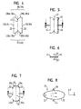
- FIGS. 1 to 3 A conventional method for producing an airbag 10, which can be used as a side airbag in a corresponding vehicle occupant restraint system, is shown with reference to FIGS. 1 to 3.
- a half 14a is folded around the center line 12, so that it comes to lie congruently on the other half 14b.
- the two superimposed layers are sewn together at their outer edges to form a seam 16 circumferentially.
- An injection opening 18 is provided in the region of the center line 12 (see FIG. 2).
- the gas bag 10 is inflated with a gas generator, at least part of the seam 16 lies in the direct flow path of the hot compressed gas (see FIG. 3).
- FIGS. 4 to 8 describe, by way of example, the production of a side airbag 20 not according to the invention.
- Two textile blanks 22, 32 shaped as shown in FIG. 4 and symmetrical with respect to a center line 42 are stacked on one plane (only the overhead blank 22 can be seen in FIG ).
- the blanks 22, 32 each have two with respect to the center line 42 opposite longitudinal edge portions 24, 26 and 34, 36 and two the longitudinal edge portions 24, 26 and 34, 36 connecting edge portions 28, 30 and 38, 40, respectively in two Subsections 28a, 28b and 30a, 30b and 38a, 38b and 40a, 40b are divided.
- the two blanks 22, 32 are first sewn together along their longitudinal edge portions 24, 26 and 34, 36 to form the seams 44, 46 (see Figure 5).
- the two blanks 22, 32 are pulled apart at the center line 42 according to the arrows in Figure 6 in opposite directions, so that the two seams 44, 46 come to rest on each other, as can be seen from the view of Figure 7, compared to the view of Figure 5 is rotated by 90 ° about the center line 42.
- the seam 48 connects the two sections 28a and 28b of the one blank 22 with each other and the two sections 38a and 38b of the other blank 32, while the seam 50, the two sections 30a and 30b of a blank 22 with each other and the two sections 40a and 40b the other blank 32 connects to each other.
- An injection opening 52 is provided similar to the conventional gas bag 10 in the region of the center line 42 in the upper blank 22.
- the side airbag 20 constructed in this way unfolds more quickly in the Y direction than the conventional airbag 10.
- none of the seams 44, 46, 48, 50 lie in the direct flow path of the hot compressed gas. The forces acting on the blanks 22, 32 during deployment are distributed over several seams, so that the load on the individual seams is reduced.
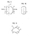
- FIGS. 9 to 11 An example of the production of a side gas bag for an assembly according to the invention is shown in FIGS. 9 to 11.
- the shape of the two textile blanks 22, 32 is not symmetrical with respect to the center line 42.
- one half 22a or 32a has a belly-like extent compared to the other half 22b or 32b .
- the airbag 20 'produced from these blanks 22, 32 has, in the inflated state, the shape shown in FIG. 11 with a flat shape Section 54 and a vehicle occupant facing the bulbous portion 56th
- FIGS. 12 to 14 for producing a side gas bag for an assembly according to the invention differs from the previously described methods, in particular in that the two textile blanks 22, 32 are not separate but are in one piece (see FIG. 12).
- the blank 32 provided with a plurality of reinforcing plies around the inflation opening 52 and nearly symmetrical with respect to a center line 58 to the blank 22 is folded rearwardly around the center line 58 as shown in FIG. 12, so that it can be seen on FIG Rear of the blank 22 comes to rest.
- the further manufacturing method corresponds to that of the previous embodiment.
- FIGS 15 to 18 In the production of a side airbag for an assembly according to the invention according to FIGS 15 to 18, two separate textile blanks 22, 32 ( Figures 15 and 16) are used, which are not completely congruent due to the desired final shape of the side airbag.
- the special course of the edge portions 24 and 34 and 26 and 36 provides later for a vehicle-occupant-facing bulbous portion and adapted to the vehicle side structure shape of the opposite portion of the side airbag.
- the illustrated embodiment e.g. the area 60 of an armrest recessed.
- the textile blank 22 shown in FIG. 15 is placed on the textile blank 32 shown in FIG.
- the further manufacturing method corresponds to that of the previous embodiments.
- the outer seams 44, 46 and 48 or 50 of the side gas bag can be routed by everting the gas bag to the inside. This can be done after formation of the seam 48 or after formation of the seam 50, before finally the seam 50 or 48 is formed.
Landscapes
- Engineering & Computer Science (AREA)
- Mechanical Engineering (AREA)
- Air Bags (AREA)
Claims (6)
- Ensemble comprenant un coussin à gaz latéral (10) pour un système de retenue de passager de véhicule et une structure latérale de véhicule, dans lequel le coussin à gaz latéral (10) se déploie entre la structure latérale de véhicule et un passager du véhicule et est réalisé à partir de deux découpes de tissu (22, 32) et dans lequel
chaque découpe (22, 32) présente respectivement un premier tronçon de bord (24, 34), un deuxième tronçon de bord (26, 36) opposé à celui-ci ainsi qu'un troisième tronçon de bord (28, 38) et un quatrième tronçon de bord (30, 40) qui relient le premier tronçon de bord (24, 34) au deuxième tronçon de bord (26, 36), le troisième tronçon de bord (28, 38) et le quatrième tronçon de bord (30, 40) sont chacun subdivisés en deux tronçon partiels (28a, 28b ; 38a, 38b) séparés par une ligne médiane (42) imaginaire et symétriques par rapport à la ligne médiane,
au moins le premier tronçon de bord (24) de ladite une découpe (22) est cousu avec le premier tronçon de bord (34) de l'autre découpe (32) en formant au moins une première couture (44),
les tronçons partiels (28a, 28b) du troisième tronçon de bord (28) de ladite une découpe (22) sont cousus les uns aux autres et les tronçons partiels (38a, 38b) du troisième tronçon de bord (38) de l'autre découpe (32) sont cousus les uns aux autres,
les tronçons partiels (30a, 30b) du quatrième tronçon de bord (30) de ladite une découpe (22) sont cousus les uns aux autres et les tronçons partiels (40a, 40b) du quatrième tronçon de bord (40) de l'autre découpe (32) sont cousus les uns aux autres, et
le premier tronçon de bord (24) de ladite une découpe (22) et le premier tronçon de bord (34) de l'autre découpe (32) ne sont pas symétriques au deuxième tronçon de bord (26) de ladite une découpe (22) et au deuxième tronçon de bord (36) de l'autre découpe (32), par rapport à la ligne médiane (42), une moitié (22a, 32a) de chaque découpe (22, 32) ayant une extension ventrue en comparaison à l'autre moitié (22b, 32b), de sorte que le coussin à gaz latéral (20') à l'état gonflé a un tronçon plat (54) et un tronçon ventru (56) tourné vers le passager du véhicule, et la couture (44) qui relie les deux découpes (22, 32) s'étend à la verticale. - Ensemble selon la revendication précédente, caractérisé en ce que les découpes textiles (22, 32) coïncident sensiblement l'une à l'autre.
- Ensemble selon l'une des revendications précédentes, caractérisé en ce que les tronçon partiels (28a, 28b ; 38a, 38b) du troisième tronçon de bord (28, 38) et/ou les tronçons partiels (30a, 30b ; 40a, 40b) du quatrième tronçon de bord (30, 40) sont symétriques par rapport à la ligne médiane (42).
- Ensemble selon l'une des revendications précédentes, caractérisé en ce que le deuxième tronçon de bord (26) aussi de ladite une découpe (22) est cousu avec le deuxième tronçon de bord (36) de l'autre découpe (32).
- Ensemble selon l'une des revendications précédentes, caractérisé en ce qu'un orifice de soufflage (52) est formé dans une découpe à l'opposé d'une zone non cousue de l'autre découpe.
- Ensemble selon l'une des revendications précédentes, caractérisé en ce que les découpes textiles (22, 32) sont réalisées d'un seul tenant l'une avec l'autre.
Applications Claiming Priority (2)
| Application Number | Priority Date | Filing Date | Title |
|---|---|---|---|
| DE2002146768 DE10246768A1 (de) | 2002-10-07 | 2002-10-07 | Gassack für ein Fahrzeuginsassen-Rückhaltesystem und Verfahren zu dessen Herstellung |
| DE10246768 | 2002-10-07 |
Publications (3)
| Publication Number | Publication Date |
|---|---|
| EP1407942A2 EP1407942A2 (fr) | 2004-04-14 |
| EP1407942A3 EP1407942A3 (fr) | 2004-11-03 |
| EP1407942B1 true EP1407942B1 (fr) | 2007-01-31 |
Family
ID=32010365
Family Applications (1)
| Application Number | Title | Priority Date | Filing Date |
|---|---|---|---|
| EP20030021675 Expired - Lifetime EP1407942B1 (fr) | 2002-10-07 | 2003-09-29 | Airbag pour un système de retenue de passager d'un véhicule et son procédé de fabrication |
Country Status (2)
| Country | Link |
|---|---|
| EP (1) | EP1407942B1 (fr) |
| DE (2) | DE10246768A1 (fr) |
Families Citing this family (3)
| Publication number | Priority date | Publication date | Assignee | Title |
|---|---|---|---|---|
| DE102005024113A1 (de) * | 2005-01-21 | 2006-08-10 | Trw Automotive Safety Systems Gmbh & Co. Kg | Gassackmodul |
| US7661708B2 (en) | 2005-01-21 | 2010-02-16 | Trw Automotive Safety Systems Gmbh | Gas bag module |
| DE102009019766A1 (de) * | 2009-04-28 | 2010-01-28 | Takata-Petri Ag | Gassack für ein Fahrzeuginsassen-Rückhaltesystem und Verfahren zum Herstellen eines Fahrzeuginsassen-Rückhaltesystems |
Family Cites Families (2)
| Publication number | Priority date | Publication date | Assignee | Title |
|---|---|---|---|---|
| JP3340354B2 (ja) * | 1997-08-04 | 2002-11-05 | 日本プラスト株式会社 | エアバッグ |
| JP2002160559A (ja) * | 2000-11-28 | 2002-06-04 | T S Tec Kk | 車両用シート |
-
2002
- 2002-10-07 DE DE2002146768 patent/DE10246768A1/de not_active Withdrawn
-
2003
- 2003-09-29 DE DE50306431T patent/DE50306431D1/de not_active Expired - Lifetime
- 2003-09-29 EP EP20030021675 patent/EP1407942B1/fr not_active Expired - Lifetime
Also Published As
| Publication number | Publication date |
|---|---|
| DE10246768A1 (de) | 2004-04-29 |
| DE50306431D1 (de) | 2007-03-22 |
| EP1407942A2 (fr) | 2004-04-14 |
| EP1407942A3 (fr) | 2004-11-03 |
Similar Documents
| Publication | Publication Date | Title |
|---|---|---|
| DE102008030188B4 (de) | Mehrkammer-Seitenairbag | |
| DE102020108400B3 (de) | OPW-Luftsack | |
| DE202014003584U1 (de) | Aufblasbarer Gassack zum Schutz einer Person, Gassackmodul, Fahrzeugteile und Fahrzeuginsassenrückhaltesystem mit einem solchen Gassack | |
| DE102010042943A1 (de) | Knieairbagmodul | |
| WO2010057607A1 (fr) | Coussin gonflable | |
| DE102007016038A1 (de) | Airbag mit Gasdiffusor | |
| DE102020124148A1 (de) | Gassack zur Reduzierung einer schlagartigen Seitwärtsbewegung eines Insassen | |
| DE102010018180A1 (de) | Gassack mit einer ersten Seitenwand und einer zweiten Seitenwand und wenigstens einem Fangband | |
| EP2424752B1 (fr) | Sac à gaz pour système de retenue d'occupants d'un véhicule et procédé de production d'un système de retenue d'occupants d'un véhicule | |
| DE10122838B4 (de) | Luftsack für ein Curtain-Airbag Modul | |
| EP3107767B1 (fr) | Coussin d'air latéral pour véhicule | |
| WO2017140521A1 (fr) | Coussin gonflable pour genou | |
| WO1998022311A1 (fr) | Sac a gaz pour un module airbag, et procede et dispositif de pliage d'un sac a gaz | |
| EP1407942B1 (fr) | Airbag pour un système de retenue de passager d'un véhicule et son procédé de fabrication | |
| DE10046604A1 (de) | Kissen zum Schutz des Kopfs eines Fahrzeuginsassen, entsprechende Schutzvorrichtung und entsprechendes Fahrzeug | |
| DE102021202717B4 (de) | Gassack für ein Fahrzeuginsassen-Rückhaltesystem eines Kraftfahrzeugs und Verfahren zum Herstellen eines Gassacks | |
| DE10246769A1 (de) | Seitenaufprall-Schutzvorrichtung | |
| DE102020134796B4 (de) | Airbagkissen für ein Fahrzeug | |
| DE102023132907A1 (de) | Luftsack, vorzugsweise OPW-Luftsack, für ein Fahrzeug | |
| WO2015173116A1 (fr) | Coussin gonflable pour genoux, module de coussin gonflable pour genoux et agencement d'un module de coussin gonflable pour genoux dans un véhicule automobile | |
| DE202022105043U1 (de) | Airbag | |
| DE202022103214U1 (de) | Gassack für eine Airbaganordnung, sowie eine Airbaganordnung mit einem solchen Gassack | |
| EP1810891B1 (fr) | Module de coussin de sécurité pour véhicules | |
| DE2525440A1 (de) | Verfahren zur herstellung eines aufblasbaren luftkissens | |
| DE102015000737B4 (de) | Gassack für ein Personen-Rückhaltesystem eines Fahrzeugs sowie Verfahren zur Herstellung des Gassackes |
Legal Events
| Date | Code | Title | Description |
|---|---|---|---|
| PUAI | Public reference made under article 153(3) epc to a published international application that has entered the european phase |
Free format text: ORIGINAL CODE: 0009012 |
|
| AK | Designated contracting states |
Kind code of ref document: A2 Designated state(s): AT BE BG CH CY CZ DE DK EE ES FI FR GB GR HU IE IT LI LU MC NL PT RO SE SI SK TR |
|
| AX | Request for extension of the european patent |
Extension state: AL LT LV MK |
|
| PUAL | Search report despatched |
Free format text: ORIGINAL CODE: 0009013 |
|
| AK | Designated contracting states |
Kind code of ref document: A3 Designated state(s): AT BE BG CH CY CZ DE DK EE ES FI FR GB GR HU IE IT LI LU MC NL PT RO SE SI SK TR |
|
| AX | Request for extension of the european patent |
Extension state: AL LT LV MK |
|
| 17P | Request for examination filed |
Effective date: 20050420 |
|
| AKX | Designation fees paid |
Designated state(s): DE ES FR IT |
|
| GRAP | Despatch of communication of intention to grant a patent |
Free format text: ORIGINAL CODE: EPIDOSNIGR1 |
|
| GRAS | Grant fee paid |
Free format text: ORIGINAL CODE: EPIDOSNIGR3 |
|
| GRAA | (expected) grant |
Free format text: ORIGINAL CODE: 0009210 |
|
| REG | Reference to a national code |
Ref country code: DE Ref legal event code: R081 Ref document number: 50306431 Country of ref document: DE Owner name: TRW AUTOMOTIVE GMBH, DE Free format text: FORMER OWNER: TRW OCCUPANT RESTRAINT SYSTEMS GMBH & CO. KG, 73553 ALFDORF, DE |
|
| RAP1 | Party data changed (applicant data changed or rights of an application transferred) |
Owner name: TRW AUTOMOTIVE GMBH |
|
| AK | Designated contracting states |
Kind code of ref document: B1 Designated state(s): DE ES FR IT |
|
| REF | Corresponds to: |
Ref document number: 50306431 Country of ref document: DE Date of ref document: 20070322 Kind code of ref document: P |
|
| REG | Reference to a national code |
Ref country code: DE Ref legal event code: R096 Ref document number: 50306431 Country of ref document: DE Effective date: 20070322 |
|
| PG25 | Lapsed in a contracting state [announced via postgrant information from national office to epo] |
Ref country code: ES Free format text: LAPSE BECAUSE OF FAILURE TO SUBMIT A TRANSLATION OF THE DESCRIPTION OR TO PAY THE FEE WITHIN THE PRESCRIBED TIME-LIMIT Effective date: 20070512 |
|
| ET | Fr: translation filed | ||
| PLBE | No opposition filed within time limit |
Free format text: ORIGINAL CODE: 0009261 |
|
| STAA | Information on the status of an ep patent application or granted ep patent |
Free format text: STATUS: NO OPPOSITION FILED WITHIN TIME LIMIT |
|
| 26N | No opposition filed |
Effective date: 20071101 |
|
| REG | Reference to a national code |
Ref country code: DE Ref legal event code: R097 Ref document number: 50306431 Country of ref document: DE Effective date: 20071101 |
|
| PG25 | Lapsed in a contracting state [announced via postgrant information from national office to epo] |
Ref country code: IT Free format text: LAPSE BECAUSE OF FAILURE TO SUBMIT A TRANSLATION OF THE DESCRIPTION OR TO PAY THE FEE WITHIN THE PRESCRIBED TIME-LIMIT Effective date: 20070131 |
|
| REG | Reference to a national code |
Ref country code: FR Ref legal event code: PLFP Year of fee payment: 14 |
|
| REG | Reference to a national code |
Ref country code: FR Ref legal event code: PLFP Year of fee payment: 15 |
|
| REG | Reference to a national code |
Ref country code: FR Ref legal event code: PLFP Year of fee payment: 16 |
|
| PGFP | Annual fee paid to national office [announced via postgrant information from national office to epo] |
Ref country code: DE Payment date: 20190930 Year of fee payment: 17 |
|
| REG | Reference to a national code |
Ref country code: DE Ref legal event code: R119 Ref document number: 50306431 Country of ref document: DE |
|
| PG25 | Lapsed in a contracting state [announced via postgrant information from national office to epo] |
Ref country code: DE Free format text: LAPSE BECAUSE OF NON-PAYMENT OF DUE FEES Effective date: 20210401 |
|
| PGFP | Annual fee paid to national office [announced via postgrant information from national office to epo] |
Ref country code: FR Payment date: 20220808 Year of fee payment: 20 |
|
| P01 | Opt-out of the competence of the unified patent court (upc) registered |
Effective date: 20230628 |