EP1407971A2 - Kunststoffflasche - Google Patents
Kunststoffflasche Download PDFInfo
- Publication number
- EP1407971A2 EP1407971A2 EP03022378A EP03022378A EP1407971A2 EP 1407971 A2 EP1407971 A2 EP 1407971A2 EP 03022378 A EP03022378 A EP 03022378A EP 03022378 A EP03022378 A EP 03022378A EP 1407971 A2 EP1407971 A2 EP 1407971A2
- Authority
- EP
- European Patent Office
- Prior art keywords
- outer shell
- plastic bottle
- inner container
- connection
- webs
- Prior art date
- Legal status (The legal status is an assumption and is not a legal conclusion. Google has not performed a legal analysis and makes no representation as to the accuracy of the status listed.)
- Withdrawn
Links
Images


Classifications
-
- B—PERFORMING OPERATIONS; TRANSPORTING
- B65—CONVEYING; PACKING; STORING; HANDLING THIN OR FILAMENTARY MATERIAL
- B65D—CONTAINERS FOR STORAGE OR TRANSPORT OF ARTICLES OR MATERIALS, e.g. BAGS, BARRELS, BOTTLES, BOXES, CANS, CARTONS, CRATES, DRUMS, JARS, TANKS, HOPPERS, FORWARDING CONTAINERS; ACCESSORIES, CLOSURES, OR FITTINGS THEREFOR; PACKAGING ELEMENTS; PACKAGES
- B65D23/00—Details of bottles or jars not otherwise provided for
- B65D23/08—Coverings or external coatings
- B65D23/0885—Rigid shells for receiving the bottle or part of it
Definitions
- the invention relates to a plastic bottle for packaging food, in particular of beverages, a method for producing such a plastic bottle and a Method for providing chilled food, in particular chilled beverages, as described in the preambles of claims 1, 27 and 33.
- Containers made of plastic materials for packaging food or beverages known for some time.
- they are particularly thin-walled bottles made of thermoplastic polyester, such as polyethylene terephthalate (PET) So-called “PET bottles” or “PET light bottles” both as disposable and as Reusable bottles in use.
- PET polyethylene terephthalate
- Such plastic bottles are preferred with special thin wall or material thicknesses.
- Stretch blow molding is a common method for manufacturing single-walled PET bottles as well as the injection molding process. Both methods are state of the art and should not be described further here.
- preforms are made -
- a process step - bottles are "blown" into the corresponding molded parts.
- At the Injection molding process is carried out using extruder PET granulate under the influence of heat Molded parts injected under high pressure.
- the object of the invention is to provide a plastic bottle with improved mechanical and to create thermal properties with the food and especially drinks can be provided inexpensively and in an energy-saving manner even in the cooled state.
- the object of the invention is achieved by a plastic bottle for packaging food, in particular of drinks, solved according to claim 1, wherein the container wall an inner container and an outer shell is formed and the outer shell at least in regions spaced from an outer surface of the inner container by a normal distance is and an upper end portion of the outer shell and an upper end portion of the inner container is connected to the shoulder part.
- the advantage of this plastic bottle is that that this can be manufactured inexpensively with little material and therefore also suitable as a single-use product, but at the same time also good dimensional stability when filled Condition and a much larger compared to single-walled plastic bottles Has thermal insulation.
- the formation of the plastic bottle, after which the mouth part and the shoulder part and the Inner containers are formed in one piece offers the advantage of being easy to manufacture.
- the best case is to produce the plastic bottle only two parts, namely the Outer shell and that formed from the mouth part, the shoulder part and the inner container Unit required.
- plastic bottle in which the mouth part is also advantageous is also advantageous a thread for connection to a sealing cap is formed, as a result of which Plastic bottle is resealable in a simple manner and therefore also multiple times can be used or provided as a reusable bottle for refilling can be.
- the formation of the plastic bottle in between the outer surface of the inner container and an inner side of the outer shell spacer elements are provided the advantage of improved dimensional stability. Because the outer shell as well as the inner container preferably with very thin wall thicknesses, the weight alone can of the food or drink filled into the interior of the plastic bottle is sufficient, to deform the inner container so far that its outer surface the inside touches the outer shell, which affects the heat insulating effect of the container wall would.
- the spacer elements between the outer Surface of the inner container and the inside of the outer shell can advantageously the relative spatial position of the outer shell with respect to the spatial position of the inner container largely unchanged.
- the plastic bottle in which the spacing elements formed by first webs formed on the inside in a base region of the outer shell are, wherein the first webs are plate-shaped and parallel and at least approximately are aligned radially to the longitudinal central axis, as this means that the outer shell and the Inner containers can be centered relative to each other.
- the outer shell and the Inner containers can be centered relative to each other.
- Spacer elements a point of increased thermal conductivity between the Given the outer shell and the inner container, through the plate-shaped design of the webs and their parallel or radial alignment with respect to the longitudinal central axis of the plastic bottle, However, these webs are only with their narrow sides with the outer shell or the inner container in contact, making the heat transfer in these areas very low can be held.
- the advantage is achieved that the plate-shaped or flat webs thereby have greater rigidity. This is particularly advantageous if the webs are both on the inside of the outer shell are also attached to the outer surface of the inner container, since then the container wall increased rigidity against torsional stress, such as when opening or closure of a threaded cap can occur, having.
- the advantage is achieved that the outer shell and the inner container are secured against undesired relative rotation.
- the plastic bottle or the connection point between the outer shell and the shoulder part of the plastic bottle with a circular cross section are formed and the connection area between the outer shell and the Shoulder area of the plastic bottle itself is not secured against rotation.
- the connection between the outer container and the shoulder area the plastic bottle does not allow twisting, through which in the recesses of the Bottom region of the inner container protruding webs of the outer shell, the torsional rigidity of the Overall container wall increased.
- the plastic bottle By forming the plastic bottle, after which the outer shell is formed in two parts is and the outer shell transversely or perpendicular to the longitudinal central axis in an outer shell upper part and an outer shell lower part is divided, offers the advantage of greater variability of the possible shapes of the container wall for the plastic bottle, since it also means other than cylindrical container walls can be produced.
- the contact edge of the outer shell upper part of the mouth part of the Plastic bottle is turned away, while the corresponding contact edge of the shoulder area faces the mouth part. It is therefore necessary that during assembly of the inner container into the outer shell of the outer shell top of which the mouth part corresponding end area of the plastic bottle coming over the inner container is, while the outer shell lower part of the opposite of the mouth part End region of the plastic bottle is placed over the inner container. This has the Advantage that after establishing the connection between the outer shell and the Outer shell lower part of the inner container is positively attached in the outer shell.
- the outer shell and the inner container with one circular cross section are formed because of the circular cross section Outer shell or the inner container overall the mechanical stability of the container wall is improved and on the other hand, the connections between the outer shell top and the Outer shell lower part and between the outer shell upper part or the outer shell and the Shoulder part of the plastic bottle can be formed by screw connections.
- the training of the plastic bottle after which the connection of the outer shell top with the outer shell lower part by a screw connection or a snap connection is formed, has the advantage that the outer shell upper part and the outer shell lower part are reversibly or releasably connected to one another.
- a further development of the plastic bottle provides that the connections between outer shell and inner container as well as between outer shell upper part and outer shell lower part are gastight.
- the space formed in the container wall between the inner container and the outer shell is therefore gas-tight towards the outside completed.
- this has the advantage that the container wall is improved has mechanical stability or improved rigidity and on the other hand the Thermal insulation of the container wall is also improved by preventing the gas exchange and the convective heat exchange is prevented.
- plastic bottle using the materials, such as polyethylene terephthalate (PET), polycarbonate (PC), polyethylene (PE), polypropylene (PP) or polyamide (PA) as this is used to manufacture the individual components of the plastic bottle known plastic processing methods, such as blow molding or stretch blow molding or injection molding.
- PET polyethylene terephthalate
- PC polycarbonate
- PE polyethylene
- PP polypropylene
- PA polyamide
- the connection of the Outer shell with the inner container or with the shoulder part by a screw connection is formed. This has the advantage of an even better or more stable connection between the individual parts of the plastic bottle.
- plastic bottle according to which there is an intermediate space between there is an object in the inner container and the outer casing, e.g. a toy, a toy part or a document, such as a prospectus, will take advantage of one increased buying incentives among consumers.
- an object in the inner container and the outer casing e.g. a toy, a toy part or a document, such as a prospectus
- connection zone between Outer shell upper part and outer shell lower part opposite end areas of the guide webs on an outside facing away from the longitudinal central axis and / or one of the longitudinal central axis facing inside bevels are formed, because thereby bringing together or connecting the outer shell upper part and the outer shell lower part is additionally facilitated.
- the object of the invention is also independent by a method for producing a Plastic bottle for packaging food, especially drinks, accordingly solved the features of claim 27.
- the advantage of this method is that it does Plastic bottles can be manufactured that are single-walled compared to conventional ones Plastic bottles have a much greater heat effect, but at the same time require only a small amount of material and are also suitable as a disposable product.
- the object of the invention is also independent by a method for providing of chilled food according to the features of claim 33 solved.
- Advantageous is that it is a cost-effective and safe transport or storage especially of perishable food or beverages.
- FIG. 1 shows a plastic bottle 1, shown in vertical section, and FIG. 2 shows one Top view of the plastic bottle 1.
- the plastic bottle 1 comprises at least one Mouth part 2, a shoulder part 3 and an interior 4 of the plastic bottle 1 enclosing container wall 5.
- This container wall 5 is at least in two parts or two shells formed and consists of an inner container 6 and an outer shell 7.
- This Outer shell 7 at least partially encloses the inner container 6 and is at least in areas from an outer surface 8 of the inner container 6 by a normal distance 9 distanced, whereby a space is formed.
- An upper end portion 10 of the The outer shell 7 and an upper end region 11 of the inner container 6 are with the shoulder part 3 connected.
- the mouth part 2, the shoulder part 3 and the inner container 6 are preferably formed in one piece, so that the plastic bottle 1 according to this embodiment consists of only two parts.
- the inner container 6 and the outer shell 7 are at least in this embodiment formed approximately cylindrical, so that the plastic bottle 1 by inserting the Inner container 6 in the outer shell 7 or sliding the outer shell 7 over the inner container 6 can be produced.
- a flange connection 12 is provided for fastening the outer shell 7 to the inner container 6 or the shoulder part 3. Through training the flange connection 12 can be ensured that the outer shell 7 or the inner container 6 are aligned concentrically to each other.
- the plastic bottle 1 thus points a common longitudinal central axis 13 for the outer shell 7 and the inner container 6.
- the Connection between the outer shell 7 and the inner container 6 can be made by any other type of connection, e.g. Snap or snap connection.
- At the mouth part 2 is a thread for making a connection or a screw connection formed with a cap.
- the Interior 4 has a capacity or a volume of 330ml.
- FIG. 3 shows a second embodiment of the plastic bottle 1, cut vertically 4, and FIG. 4 is a top view of the plastic bottle 1. To avoid unnecessary repetitions To avoid the same component names and reference numerals for the same parts used and referred to the detailed description in FIGS. 1 and 2 or referred.
- the interior 4 of the plastic bottle 1 is initially enclosed by the inner container 6, that in its upper end region 10 with a shoulder part 3 and subsequently with one Mouth part 2 is connected.
- the outer surface 8 of the inner container 6 is of the Surround outer shell 7, the outer surface 8 of the inner container 6 at least in some areas is spaced from the outer shell 7 by the normal distance 9 and thus between a space 14 is formed on the outer surface 8 and the outer shell 7. With its upper end region 10 is the outer shell 7 in the transition region between the Shoulder part 3 and the mouth part 2 connected to the shoulder part 3.
- the plastic bottle 1 is in a multi-stage process first the inner container 6 manufactured and then the outer shell 7 with the inner container 6 fixed and permanently connected.
- the outer shell 7 consists of two parts.
- the outer shell 7 can, for example, by injection molding two vertical divisions of the outer shell 7 corresponding halves can be produced.
- the two halves of the outer shell 7 are then enclosing the inner container 6 together, the connection zones can be sealed airtight or gastight.
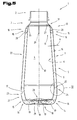
- Fig. 5 shows a third embodiment of the plastic bottle 1, cut vertically shown.
- the container wall 5 of the plastic bottle 1 according to this embodiment is also formed by an inner container 6 and an outer shell 7. Mouth part 2, Shoulder part 2 and inner container 6 form a unit and are preferably in one piece educated.
- a plurality of spacing elements 15 are arranged in the space 14 between the outer shell 7 and the outer surface 8 of the inner container 6, .
- These will here formed by plate-shaped webs 16, which are preferably on an inside 17 are usually attached by molding in the same manufacturing process.
- the spatial Alignment of the plate-shaped webs 16 is provided so that the webs 16 both parallel to the longitudinal central axis 13 and radially to this longitudinal central axis 13 are directed.
- a bottom region 18 of the outer casing 7 there are first ones on the inside Ridges 19 arranged, e.g. molded on, while in the upper end region 10 of the outer shell 7 arranged on the inside 17 second webs 20, e.g. are molded.
- the first webs 19 of the bottom region 18 of the outer shell 7 extend between the Inner side 17 of a side wall region 21 and the inner side 17 of the bottom region 18 of the Outer shell 7.
- the webs 19 arranged in this way give the bottom region 18 of the outer shell 7 greater rigidity. At the same time, this also supports the inner container 6 created with formation of a predetermined distance. Beyond that it is but it is also still possible for individual webs or ribs to be arranged in the intermediate space 14 are and proceed from the bottom area 18 to the end area 10. These bridges or ribs can run continuously or only in regions over the longitudinal extent be arranged, these on the inside 17 of the outer shell 7 and / or on the outer Surface 8 of the inner container 8 can be molded.
- the number as well as the arrangement the same can be done arbitrarily over the circumference, with a parallel as well as radial alignment to the longitudinal central axis 13 is preferred. Through these ribs or webs an improved stability of the entire plastic bottle 1 during its intended use Use achieved.
- the outer shell 7 in two parts, namely from an outer shell upper part 22 and an outer shell lower part 23 is formed.
- the outer shell 7 is perpendicular to the plane
- the longitudinal central axis 13 of the plastic bottle 1 is divided, i.e. between the outer shell top 22 and the outer shell lower part 23, a connection 24 is provided, with one Connection zone 25 between the outer shell upper part 22 and the outer shell lower part 23 extends transversely to the longitudinal central axis 13 of the plastic bottle 1.
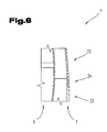
- the formation of the connection 24 is described in more detail below with reference to FIG. 6.
- a flange 12 is formed for connecting the outer shell 7 or the outer shell upper part 22 to the shoulder part 3 or the inner container 6, a flange 12 is formed. There is a flange system side 26 facing away from the mouth part 2 of the plastic bottle 1, while a flange contact side 27 of the shoulder part 3 faces the mouth part 2.
- the outer shell 7 on the inner container 6 or the shoulder part 3 is thus the outer shell upper part 22 coming from the mouth portion 2 facing end region of the plastic bottle 1 to put over the inner container 6 until the flange side 26 of the outer shell upper part 22 abuts the flange contact side 27 of the shoulder part 3.
- the one in the outer shell top 22 provided webs 20 facilitate centering and assembly as well if necessary, locking the parts. All that remains for complete assembly is the Outer shell lower part 23 of the opposite end region of the mouth part 2 Plastic bottle 1 coming to slip on and the outer shell top 22 and To secure the outer shell lower part 23 to one another by establishing the connection 24.
- a bottom area 28 of the inner container facing the bottom area 18 of the outer casing 7 6 is designed such that the outer surface is aligned radially to the longitudinal central axis 13 Elevations 29 and depressions 30 forms.
- the elevations 29 and depressions 30 are distributed with respect to the longitudinal center axis 13 in such a way that the webs 19 of the outer shell lower part 23 when assembled with the inner container 6 or the outer shell upper part 22 protrude into the recesses 30 of the bottom region 28 of the inner container 6.
- the flange 12 between the shoulder part 3 and the outer shell 7 and / or in the connection 24 of the outer shell upper part 22 with the outer shell lower part 23 is preferred provided that these are gas-tight.
- This will increase both the stiffness or mechanical stability of the plastic bottle 1 improved overall and on the other hand achieved the thermal insulation effect of the entire double-shell container wall 5 is increased because the convective heat exchange is almost completely but also entirely is prevented.
- the rigidity or mechanical stability of the plastic bottle 1 is in particular also increased by the fact that the inner container 6 and the outer casing 7 are preferably formed with a circular cross section.
- FIG. 6 shows a detail of the plastic bottle 1 according to FIG. 5.
- the connection 24 between the outer shell upper part 22 and the outer shell lower part 23 is according to this embodiment formed by a snap connection. In the case of one with one Circular cross-section formed outer shell 7, the connection 24 can also be formed by a screw connection.
- connection points of the individual components of the plastic bottle 1 can additionally also by gluing or welding or similar connection methods in one cannot be removed again. This can make the connection points gas-tight be ensured. Furthermore, it is also possible to use the space in between 14 before gluing or welding to one against the outside air pressure lowering the pressure or evacuating it completely.
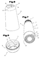
- FIGS. 5 and 6 show the individual components for forming the plastic bottle 1 as one corresponding structural unit according to the embodiment according to FIGS. 5 and 6 shown in perspective in the non-assembled state.
- the unit formed from the mouth part 2, the shoulder part 3 and the inner container 6 is shown seen obliquely from below, while the outer shell 22 and the Outer shell lower part 23 are shown viewed obliquely from above.
- On the inside 17 of the upper end region 10 of the outer shell upper part 22 is one of the webs 20 see.
- two of the webs are in the bottom region 18 of the outer shell lower part 23 19, which are integrally formed on the inside 17 of the outer shell lower part 23.
- the elevations are on the bottom area 28 of the inner container 6 facing the viewer 29 and depressions 30, which are distributed around the circumference of the base region 28, can be seen.
- the webs 20 of the outer shell upper part 22 are supported from the outer surface 8 on the upper end region 11 of the inner container 6 (FIG. 5).
- the webs 19 of the outer shell lower part 23 protrude into the depressions 30 in the base region 18 of the inner container 6. This also ensures that the inner container 6 and the outer shell lower part 23 are secured against relative rotation.
- FIG. 10 shows a further exemplary embodiment of a plastic bottle 1, cut vertically shown.
- the container wall 5 of the plastic bottle 1 is double-walled, a first Part of the container wall 5 through the outer shell 7 and a second part of the container wall 5 is formed by the inner container 6.
- the outer shell 7 is formed at least in two parts and includes the outer shell top 22 and the outer shell bottom 23.
- the outer shell upper part 22 in turn consists of two parts which are connected by a connection running perpendicular to the longitudinal central axis 13 41 are attached to each other.
- the spacing elements 15, which are designed as webs 16 are provided to fix the relative position of the inner container 6 opposite the outer shell 7 .
- the first webs 19 are formed in the bottom area 18 in the outer shell lower part 23. Next these are arranged in the outer shell lower part 23 on the inside 17 guide webs 42, by an additional support of the inner container 6 in relation to the outer shell 7 in lateral direction is reached.
- the first webs 19 and the guide webs 42 are each formed contiguously.
- the guide webs 42 are plate-shaped and parallel or radial aligned with the longitudinal central axis 13. Through the coherent training of the first Crosspieces 19 with the respective guide crosspieces 42 have a higher mechanical overall Stability.
- the guide webs 42 are parallel in the direction extend to the longitudinal center axis 13 into the area of the outer shell upper part 22. that is, that the guide webs 22 via the connection zone 25 or the connection 24 between protrude the outer shell upper part 22 and the outer shell lower part 23 or this connection zone 25 tower above.
- Upper end regions 43 of the guide webs 42 are thus in the assembled state in the space 14 in the area between the inner container 6 and the outer shell upper part 22.
- the end regions 43 of the guide webs 42 are also rounded or bevels 44 provided.
- the roundings or bevels 44 on the End zone 43 of the guide web 42 facing away from the connecting zone 25 are on one of the Outer side 45 facing away from longitudinal center axis 13 and / or on one of longitudinal longitudinal axis 13 facing inside 46 of the guide web 42 is formed.
- guide webs 42 in the outer shell lower part 23 it is also possible for guide webs on the inside 17 of the outer shell upper part 22 or on the To provide surface 8 of the inner container 6.
- the second webs 20 on the inside 17 of the outer shell upper part 22 provided with roundings or bevels 44.
- the connection of the Outer shell upper part 22 with the inner container 6 in the upper end region 10 or on the shoulder part 3 of the plastic bottle 1 is realized in that the outer shell upper part 22 a downward-facing contact edge 47 and the shoulder part 3 of the inner container 6 with an upward facing edge 48 corresponding to the shape of the facing edge 47 are formed.
- the contact edges 47, 48 are thereby by a transition area, which each consisting of a cylindrical area and an adjoining flange contact side 26 or 27 composed, formed.
- the cylindrical regions of the contact edges 47, 48 are designed with corresponding diameters.
- the investment margin 47 and the Flange contact side 26 of the outer shell upper part 22 faces away from the mouth part 2, during the contact edge 48 the flange contact side 27 of the shoulder part 3 the mouth part 2 faces and in the assembled state these contact edges 47, 48 to one another issue.
- the contact edges 47, 48 and the connection 24 between the outer shell upper part 22 and the outer shell lower part 23 can additionally be glued to one another, so that the Gap 14 of the container wall 5 of the plastic bottle 1 is sealed gas-tight.
- the connection points between the inner container 6 and the outer shell upper part 22 in the region of the shoulder part 3 as well as the connection 24 can be sealed tightly by welding.
- Fig. 11 shows a third embodiment of the plastic bottle 1, cut vertically shown.
- connection between the inner container 6 takes place and the outer shell upper part 22 in the region of the shoulder part 3 of the inner container 6 a screw connection 49 in which on the outer shell upper part 22 or on the inner container 6 corresponding threads are formed.
- space 14 between the inner container 6 and the outer shell upper part 22 are as further spacing elements 15 in Area between the connection zone 25 and the upper end area 10 of the outer shell upper part 22 further webs 50 are arranged.
- the Crosspieces 20 and the crosspieces 50 are designed contiguously and extend over the entire Extend the longitudinal region of the outer shell upper part in the direction of the longitudinal central axis 13.
- the first Crosspieces 19 and the guide crosspieces 42 each independently on the inside 17 or are formed in the bottom region 18 of the outer shell lower part 23.
- connection 24 designed as a snap connection (see FIG. 6) between the outer shell upper part 22 and the outer shell lower part 23 is sealed gas-tight by gluing.
- a further exemplary embodiment of the plastic bottle 1 is cut vertically in FIG. 12 shown.
- the outer shell upper part 22 lies with its contact edge 47, which faces away from the mouth part is, i.e. points downwards, on the contact edge 48 of the shoulder part 3 of the inner container 6 on.
- the first webs 19 are supported in the bottom area of the outer shell lower part 23 in the recesses 30 of the inner container 6.
- the outer shell top 22 and the Outer shell lower part 23 are formed by the connection 24 designed as a snap connection attached to each other and are thus fixed to the inner container 6. According to this embodiment it is provided that in the space 14 between the inner container 6 and the Outer shell 7 an object 51 is included.
- Item 21 may e.g.
- an additional product like a promotional item, a toy or toy part, but also a folded one Be a document with information about a competition. Because that as a snap connection trained connection 24 opened and closed again , it is possible that the item 51 by the consumer or buyer of the Plastic bottle 1 can be removed, whereupon the plastic bottle 1 is put back together can be.
- the plastic bottle 1 according to the invention thus serves at the same time not only the transport of a food or drink located in the interior 4 but also an object 51 in the form of an additional product.
- Thermoplastic materials are preferably used to produce the plastic bottle 1 according to the invention.
- Materials from the group of polyethylene terephthalate (PET), polycarbonate (PC), polyethylene (PE), polypropylene (PP) or polyamide (PA) are used. These materials can advantageously by known plastic processing methods such as blow molding or stretch blow molding or injection molding.
- the individual components of the plastic bottle 1, i.e. the inner container 6 with the shoulder part 3 and the mouth part 2 on the one hand and the parts of the outer shell 7, i.e. the outer shell top 22 and the outer shell lower part 23, on the other hand, are preferably made of two different plastics.
- Polyethylene terephthalate is preferred for the inner container 6 (PET) and 7 polypropylene (PP) are used for the outer shell.
- PET polyethylene terephthalate
- PP polypropylene
- the inner container 6 is thereby formed by stretch blow molding or by a stretch blow molding process, whereas the outer shell upper part 22 and the outer shell lower part 23 of the outer shell 7 be produced by injection molding or an injection molding process. Due to the double-walled Formation of the plastic bottle 1, it is now also possible, the inner container 6 compared to single-wall PET bottles with a particularly thin wall form, because the plastic bottle 1 due to the double wall increased stability having.
- the inner container is first used 6 produced by a stretch blow molding process from polyethylene terephthalate (PET), with the other Shoulder part 3 a contact edge extending perpendicularly with respect to the longitudinal central axis 13 48, which faces the mouth part. Then the outer shell top 22 and the outer shell lower part 23 of the outer shell 7 by injection molding Polypropylene (PP) made, at least in the bottom region 18 of the outer shell lower part 23 webs 19 are arranged and in the upper end region 10 of the outer shell upper part 22 an abutment edge 47, which faces away from the mouth part 2, is formed. The outer shell top 22 is then placed over the inner container 6 and with its contact edge 47 applied to the contact edge 48 of the outer shell upper part 22.
- PET polyethylene terephthalate
- PP Polypropylene
- outer shell lower part 23 is then from the opposite direction, i.e. from below over the inner container 6 and with the first webs 19 of the inner container 6 or its underside.
- Outer shell shell 22 and outer shell lower part 23 are made simultaneously by forming the connection 24 attached to each other.
- an object 51 can be inserted.
- the plastic bottle 1 With the plastic bottle 1 according to the invention, several needs of consumers can now or customers of the food retail trade are satisfied. So far there has been one relatively rapid heating of products that are in a cooled state, e.g. in refrigerated display cases are offered for sale, the plastic bottle 1 this reheating can be prevented for a much longer period. simultaneously the plastic bottle 1 has an improved dimensional stability and does not occur as with the usual thin-walled plastic bottles to deform the container walls solely due to the weight of the contents, if the bottle e.g. for pouring the content is held in a drinking glass in the hand and is inclined at an angle.
- this unit is also available as a disposable bottle well suited, since their components are easy to recycle without them in their Individual components must be separated before disposal.
- plastic bottle 1 With the plastic bottle 1 according to the invention it is also possible to provide a method of chilled foods or chilled beverages.
- This method initially comprises the assembly of the individual parts of the plastic bottle 1 the outer shell 7 and through the inner container 6, the shoulder part 3 and the mouth part 2 unit formed.
- the plastic bottle is then filled 1 with the food or drink and closing the plastic bottle 1 with a cap.
- the advantage is that it is there not to reheat the filled food or drink by ingestion of heat coming from the container wall, as is usually the case when a chilled beverage or food is placed in a thermos.
- the method of providing chilled food, especially chilled food Beverages thus includes at least the following process steps. First, one plastic bottle 1 according to the invention produced as described above, and then filled by the manufacturer of the food or by the filler with the food and then the filled plastic bottle 1 cooled. The filled plastic bottle 1 is then transported to the dealer or middleman. The food can be in the be filled in an uncooled or pre-cooled state. This method proves to be particularly useful for heat-sensitive foods or beverages, e.g. Milk or yogurt products that go all the way from the manufacturer to the consumer should be kept in a cooled state as advantageous. After transportation the filled plastic bottle 1 to the dealer or middleman is preferred stored in a refrigerator or in a refrigerated display case or made available for sale. In addition to the protection of perishable food that is achieved during delivery is also by the use of the plastic bottle 1 of the invention Advantage of lower energy consumption achieved by the dealer or intermediary, because the customer receives the products already delivered in a pre-cooled condition.
- Advantage of lower energy consumption achieved by the dealer or intermediary because
- the object of this invention is in particular the production of a double-walled PET bottle, has the corresponding thermal insulation function.
- the technical task consists in the development of this disposable PET bottle based on the existing ones mentioned above Process (the goal is a "disposable thermos" made of PET).
- the invention of a double-walled disposable PET bottle is basically by means of both Technical process described above can be produced. Both methods provide a double wall Disposable PET bottle with identical properties with regard to its thermal insulation capacity.
- Stretch blow molding process according to FIG. 1 The stretch blow molding process is a multi-stage process to go out: production of an "inner bottle”, production of an “outer bottle” and airtight connection of both bottles (thread closure, clip closure).
- Injection molding process as shown in Fig. 2 This process is in a one-step Process through appropriately designed molded parts a double-walled disposable PET bottle manufactured.
- the double-walled disposable PET bottle produced in this way is characterized by the fact that it has a thermal insulation effect. A warming, respectively cooling of the products filled in it takes place only with a considerable time delay compared to existing disposable PET bottles.
- the double-walled disposable PET bottle for packaging food is further characterized in that an insulation layer exists between the vessel walls and that the bottle is either in a multi-stage Process (Fig. 1, "bottle in bottle principle", this is a correspondingly airtight Connection between the bottles necessary) or in a process this isolation cavity is produced (Fig. 3).
- FIGS. 1, 2; 3, 4; 5, 6, 7, 8, 9; 10; 11 and 12 Embodiments form the subject of independent solutions according to the invention.
- the relevant tasks and solutions according to the invention are the detailed descriptions these figures.
Landscapes
- Engineering & Computer Science (AREA)
- Mechanical Engineering (AREA)
- Containers Having Bodies Formed In One Piece (AREA)
Abstract
Description
- Fig. 1
- eine erfindungsgemäße Kunststoffflasche, vertikal geschnitten und vereinfachter schematischer Darstellung;
- Fig. 2
- die Kunststoffflasche nach Fig. 1 in Draufsicht;
- Fig. 3
- ein zweites Ausführungsbeispiel einer erfindungsgemäßen Kunststoffflasche, vertikal geschnitten und vereinfachter schematischer Darstellung;
- Fig. 4
- die Kunststoffflasche nach Fig. 3 in Draufsicht;
- Fig. 5
- ein drittes Ausführungsbeispiel einer erfindungsgemäßen Kunststoffflasche, vertikal geschnitten und vereinfachter schematischer Darstellung;
- Fig. 6
- ein Detail der Kunststoffflasche gemäß Fig. 5;
- Fig. 7
- den Innenbehälter zur Bildung der Kunststoffflasche entsprechend dem Ausführungsbeispiel gemäß den Fig. 5 und 6 im nicht zusammengebauten Zustand, in perspektivisch vereinfachter Darstellung;
- Fig. 8
- einen Teil der Außenhülle zur Bildung der Kunststoffflasche entsprechend dem Ausführungsbeispiel gemäß den Fig. 5 und 6 im nicht zusammengebauten Zustand, in perspektivisch vereinfachter Darstellung;
- Fig. 9
- einen weiteren Teil der Außenhülle zur Bildung der Kunststoffflasche entsprechend dem Ausführungsbeispiel gemäß den Fig. 5 und 6 im nicht zusammengebauten Zustand, in perspektivisch vereinfachter Darstellung;
- Fig. 10
- ein zweites Ausführungsbeispiel einer Kunststoffflasche, vertikal geschnitten dargestellt;
- Fig. 11
- ein drittes Ausführungsbeispiel der Kunststoffflasche, vertikal geschnitten dargestellt;
- Fig. 12
- ein viertes Ausführungsbeispiel der Kunststoffflasche, vertikal geschnitten dargestellt.
- 1
- Kunststoffflasche
- 2
- Mündungsteil
- 3
- Schulterteil
- 4
- Innenraum
- 5
- Behälterwand
- 6
- Innenbehälter
- 7
- Außenhülle
- 8
- Oberfläche
- 9
- Normalabstand
- 10
- Endbereich
- 11
- Endbereich
- 12
- Flanschverbindung
- 13
- Längsmittelachse
- 14
- Zwischenraum
- 15
- Distanzierungselement
- 16
- Steg
- 17
- Innenseite
- 18
- Bodenbereich
- 19
- Steg
- 20
- Steg
- 21
- Seitenwandbereich
- 22
- Außenhüllenoberteil
- 23
- Außenhüllenunterteil
- 24
- Verbindung
- 25
- Verbindungszone
- 26
- Flanschanlageseite
- 27
- Flanschanlageseite
- 28
- Bodenbereich
- 29
- Erhebung
- 30
- Vertiefung
- 41
- Verbindung
- 42
- Führungssteg
- 43
- Endbereich
- 44
- Abschrägung
- 45
- Außenseite
- 46
- Innenseite
- 47
- Anlagerand
- 48
- Anlagerand
- 49
- Schraubverbindung
- 50
- Steg
- 51
- Gegenstand
Claims (34)
- Kunststoffflasche (1) zur Verpackung von Lebensmitteln, insbesondere von Getränken, mit einem Mündungsteil (2), einem Schulterteil (3) und einer Behälterwand (5), wobei die Behälterwand (5) aus einem Innenbehälter (6) und einer Außenhülle (7) gebildet ist, und die Außenhülle (7) zumindest bereichsweise von einer äußeren Oberfläche (8) des Innenbehälters (6) um einen Normalabstand (9) distanziert ist und ein oberer Endbereich (10) der Außenhülle (7) und ein oberer Endbereich (11) des Innenbehälters (6) an dem Schulterteil (3) aneinander liegen, dadurch gekennzeichnet, dass die Behälterwand (5) zumindest zweiteilig ausgebildet ist, wobei ein erster Teil der Behälterwand (5) durch die Außenhülle (7) und ein zweiter Teil der Behälterwand (5) durch den Innenbehälter (6) gebildet sind und wobei der Mündungsteil (2), der Schulterteil (3) und der Innenbehälter (6) einteilig ausgebildet sind und die Außenhülle (7) zumindest zweiteilig ausgebildet ist und einen Außenhüllenoberteil (22) und einen Außenhüllenunterteil (23) umfasst, wobei sich eine Verbindungszone (25) einer Verbindung (24) zwischen dem Außenhüllenoberteil (22) und dem Außenhüllenunterteil (23) quer zur Längsmittelachse (13) erstreckt und zwischen der äußeren Oberfläche (8) des Innenbehälters (6) und einer Innenseite (17) der Außenhülle (7) Distanzierungselemente (15) angeordnet sind und die Distanzierungselemente (15) durch an der Innenseite (17) in einem Bodenbereich (18) der Außenhülle (7) angeformte erste Stege (19) gebildet sind.
- Kunststoffflasche (1) nach Anspruch 1, dadurch gekennzeichnet, dass die ersten Stege (19) plattenförmig ausgebildet und parallel und zumindest annähernd radial zur Längsmittelachse (13) ausgerichtet sind.
- Kunststoffflasche (1) nach Anspruch 1 oder 2, dadurch gekennzeichnet, dass die Verbindung der Außenhülle (7) mit dem Innenbehälter (6) bzw. mit dem Schulterteil (3) durch einen sich senkrecht bezüglich der Längsmittelachse (13) erstreckenden Anlagerand (47) des Außenhüllenoberteils (22) und einen Anlagerand (48) des Schulterteils (3) ausgebildet ist, wobei der Anlagerand (47) des Außenhüllenoberteils (22) dem Mündungsteil (2) abgewandt ist und der Anlagerand (48) des Schulterteils (3) dem Mündungsteil (2) zugewandt ist und die Anlageränder (47, 48) aneinander liegen.
- Kunststoffflasche (1) nach Anspruch 1 oder 2, dadurch gekennzeichnet, dass die Verbindung der Außenhülle (7) mit dem Innenbehälter (6) bzw. mit dem Schulterteil (3) durch eine Schraubverbindung (49) gebildet ist.
- Kunststoffflasche (1) nach einem der vorhergehenden Ansprüche, dadurch gekennzeichnet, dass die äußere Oberfläche (8) des Innenbehälters (6) in dem Bodenbereich (28) des Innenbehälters (6) durch radial zur Längsmittelachse (13) ausgerichtete Erhebungen (29) und Vertiefungen (30) gebildet ist.
- Kunststoffflasche (1) nach einem der vorhergehenden Ansprüche, dadurch gekennzeichnet, dass die ersten Stege (19) der Außenhülle (7) in die Vertiefungen (30) des Bodenbereichs (28) des Innenbehälters (6) eingreifen.
- Kunststoffflasche (1) nach einem der vorhergehenden Ansprüche, dadurch gekennzeichnet, dass sich die ersten Stege (19) zwischen einer Innenseite (17) eines Seitenwandbereichs (21) der Außenhülle (7) und der Innenseite (17) des Bodenbereichs (18) der Außenhülle (7) erstrecken.
- Kunststoffflasche (1) nach einem der vorhergehenden Ansprüche, dadurch gekennzeichnet, dass die Verbindung (24) des Außenhüllenoberteils (22) mit dem Außenhüllenunterteil (23) durch eine Schnappverbindung gebildet ist.
- Kunststoffflasche (1) nach einem der Ansprüche 1 bis 7, dadurch gekennzeichnet, dass die Verbindung (24) durch eine Schraubverbindung gebildet ist.
- Kunststoffflasche (1) nach einem der vorhergehenden Ansprüche, dadurch gekennzeichnet, dass sich in einem Zwischenraum (14) zwischen dem Innenbehälter (6) und der Außenhülle (7) ein Gegenstand (51) befindet.
- Kunststoffflasche (1) nach einem der vorhergehenden Ansprüche, dadurch gekennzeichnet, dass der Gegenstand (51) herausnehmbar ist.
- Kunststoffflasche (1) nach einem der vorhergehenden Ansprüche, dadurch gekennzeichnet, dass der Gegenstand (51) durch ein Schriftstück und/oder ein Spielzeug bzw. ein Spielzeugteil gebildet ist.
- Kunststoffflasche (1) nach einem der vorhergehenden Ansprüche, dadurch gekennzeichnet, dass die Verbindung (24) durch Verkleben oder Verschweißen gebildet ist.
- Kunststoffflasche (1) nach einem der vorhergehenden Ansprüche, dadurch gekennzeichnet, dass die Verbindung der Außenhülle (7) mit dem Innenbehälter (6) und die Verbindung (24) des Außenhüllenoberteils (22) mit dem Außenhüllenunterteil (23) gasdicht ausgebildet ist.
- Kunststoffflasche (1) nach einem der vorhergehenden Ansprüche, dadurch gekennzeichnet, dass weitere Distanzierungselemente (15) durch an der Innenseite (17) in dem oberen Endbereich (10) der Außenhülle (7) angeformte zweite Stege (20) gebildet sind.
- Kunststoffflasche (1) nach einem der vorhergehenden Ansprüche, dadurch gekennzeichnet, dass die zweiten Stege (20) plattenförmig ausgebildet und parallel und zumindest annähernd radial zur Längsmittelachse (13) ausgerichtet sind.
- Kunststoffflasche (1) nach einem der vorhergehenden Ansprüche, dadurch gekennzeichnet, dass Stege (19, 20) oder Rippen im Zwischenraum (14) ausgehend vom Bodenbereich (18) hin zum Endbereich (10) verlaufen.
- Kunststoffflasche (1) nach einem der vorhergehenden Ansprüche, dadurch gekennzeichnet, dass in dem Außenhüllenoberteil (22) und/oder in dem Außenhüllenunterteil (23) als Distanzierungselemente (15) Führungsstege (42) ausgebildet sind, wobei die Führungsstege (42) die Verbindungszone (25) zwischen dem Außenhüllenoberteil (22) und dem Außenhüllenunterteil (23) bezüglich einer zur Längsmittelachse (13) parallelen Richtung überragen.
- Kunststoffflasche (1) nach einem der vorhergehenden Ansprüche, dadurch gekennzeichnet, dass die Führungsstege (42) in einem der Verbindungszone (25) abgewandten Endbereich (43) an einer der Längsmittelachse (13) abgewandten Außenseite (45) und/oder an einer der Längsmittelachse (13) zugewandten Innenseite (46) mit einer Abschrägung (44) oder Abrundung ausgebildet sind.
- Kunststoffflasche (1) nach einem der vorhergehenden Ansprüche, dadurch gekennzeichnet, dass der Mündungsteil (2) mit einem Gewinde zur Verbindung mit einer Verschlusskappe ausgebildet ist.
- Kunststoffflasche (1) nach einem der vorhergehenden Ansprüche, dadurch gekennzeichnet, dass die Außenhülle (7) und der Innenbehälter (6) mit einem kreisförmigen Querschnitt ausgebildet sind.
- Kunststoffflasche (1) nach einem der vorhergehenden Ansprüche, dadurch gekennzeichnet, dass der Werkstoff zur Bildung derselben aus einem thermoplastischen Material aus der Gruppe von Polyethylenterephthalat (PET), Polycarbonat (PC), Polyethylen (PE), Polypropylen (PP), Polyamid (PA), ausgewählt ist.
- Kunststoffflasche (1) nach einem der vorhergehenden Ansprüche, dadurch gekennzeichnet, dass der Innenbehälter (6) aus Polyethylenterephthalat (PET) hergestellt ist.
- Kunststoffflasche (1) nach einem der vorhergehenden Ansprüche, dadurch gekennzeichnet, dass die Außenhülle (7) aus Polypropylen (PP) hergestellt ist.
- Kunststoffflasche (1) nach einem der vorhergehenden Ansprüche, dadurch gekennzeichnet, dass der Innenbehälter (6) durch ein Streckblasverfahren hergestellt ist.
- Kunststoffflasche (1) nach einem der vorhergehenden Ansprüche, dadurch gekennzeichnet, dass die Außenhülle (7) durch ein Spritzgießverfahren hergestellt ist.
- Verfahren zur Herstellung einer Kunststoffflasche (1) zur Verpackung von Lebensmitteln, insbesondere von Getränken, wobei die Kunststoffflasche (1) einen Mündungsteil (2), einen Schulterteil (3) und eine Behälterwand (5) umfasst und die Behälterwand (5) aus einem Innenbehälter (6) und einer Außenhülle (7) gebildet ist und wobei die Außenhülle (7) zumindest bereichsweise von einer äußeren Oberfläche (8) des Innenbehälters (6) um einen Normalabstand (9) distanziert ist und ein oberer Endbereich (10) der Außenhülle (7) und ein oberer Endbereich (11) des Innenbehälters (6) an dem Schulterteil (3) aneinander liegen, dadurch gekennzeichnet, dassder Innenbehälter (6) durch ein Streckblasverfahren aus Polyethylenterephthalat (PET) hergestellt wird, wobei an dem Schulterteil (3) ein sich senkrecht bezüglich einer Längsmittelachse (13) erstreckender Anlagerand (48), der dem Mündungsteil (2) zugewandt ist, ausgeformt wird unddie Außenhülle (7) aus einem Außenhüllenoberteil (22) und einen Außenhüllenunterteil (23) hergestellt wird, wobei der Außenhüllenoberteil (22) und/oder der Außenhüllenunterteil (23) durch ein Spritzgießverfahren aus Polypropylen (PP) hergestellt wird und zumindest in einem Bodenbereich (18) an einer Innenseite (17) der Außenhülle (7) erste Stege (19) angeordnet werden und in einem oberen Endbereich (10) des Außenhüllenoberteils (22) ein Anlagerand (47), der dem Mündungsteil (2) abgewandt ist, ausgeformt wird undder Außenhüllenoberteil (22) über den Innenbehälter (6) gestülpt und mit seinem Anlagerand (47) an den Anlagerand (48) des Innenbehälters (6) angelegt wird undder Außenhüllenunterteil (23) über den Innenbehälter (6) gestülpt wird und mit den ersten Stegen (19) an den Innenbehälter (6) angelegt wird und der Außenhüllenunterteil (23) und der Außenhüllenoberteil (22) durch eine Verbindung (24) aneinander befestigt werden.
- Verfahren nach Anspruch 27, dadurch gekennzeichnet, dass in einen Zwischenraum (14) zwischen dem Innenbehälter (6) und der Außenhülle (7) ein Gegenstand (51) eingelegt wird.
- Verfahren nach Anspruch 27 oder 28, dadurch gekennzeichnet, dass der Anlagerand (47) des Innenbehälters (6) und der Anlagerand (48) des Außenhüllenoberteils (22) gasdicht miteinander verbunden werden.
- Verfahren nach einem der Ansprüche 27 bis 29, dadurch gekennzeichnet, dass die Verbindung (24) gasdicht ausgeführt wird.
- Verfahren nach einem der Ansprüche 27 bis 30, dadurch gekennzeichnet, dass die Verbindung (24) durch Kleben oder Schweißen hergestellt wird.
- Verfahren nach einem der Ansprüche 27 bis 31, dadurch gekennzeichnet, dass der Anlagerand (48) des Innenbehälters (6) und der Anlagerand (47) des Außenhüllenoberteils (22) durch Kleben oder Schweißen miteinander verbunden werden.
- Verfahren zum Bereitstellen von gekühlten Lebensmitteln, insbesondere von gekühlten Getränken, dadurch gekennzeichnet, dasseine Kunststoffflasche (1) gemäß einem Verfahren nach einem der Ansprüche 27 bis 32 hergestellt wird unddie Kunststoffflasche (1) bei einem Hersteller bzw. Befüller des Lebensmittels mit dem Lebensmittel befüllt wird unddie befüllte Kunststoffflasche (1) gekühlt und anschließend zu einem Händler bzw. Zwischenhändler transportiert wird oderdie befüllte Kunststoffflasche (1) zu einem Händler bzw. Zwischenhändler transportiert und anschließend gekühlt wird.
- Verfahren nach Anspruch 33, dadurch gekennzeichnet, dass die befüllte Kunststoffflasche (1) bei dem Händler bzw. Zwischenhändler in einem Kühlgerät bzw. einer Kühlvitrine gelagert wird.
Applications Claiming Priority (5)
| Application Number | Priority Date | Filing Date | Title |
|---|---|---|---|
| AT6722002 | 2002-10-09 | ||
| AT6722002U | 2002-10-09 | ||
| AT6722002 | 2002-10-09 | ||
| AT6702003 | 2003-05-05 | ||
| AT6702003 | 2003-05-05 |
Publications (3)
| Publication Number | Publication Date |
|---|---|
| EP1407971A2 true EP1407971A2 (de) | 2004-04-14 |
| EP1407971A8 EP1407971A8 (de) | 2004-09-29 |
| EP1407971A3 EP1407971A3 (de) | 2005-02-02 |
Family
ID=32031279
Family Applications (1)
| Application Number | Title | Priority Date | Filing Date |
|---|---|---|---|
| EP20030022378 Withdrawn EP1407971A3 (de) | 2002-10-09 | 2003-10-06 | Kunststoffflasche |
Country Status (1)
| Country | Link |
|---|---|
| EP (1) | EP1407971A3 (de) |
Family Cites Families (3)
| Publication number | Priority date | Publication date | Assignee | Title |
|---|---|---|---|---|
| CA1251744A (en) * | 1983-04-22 | 1989-03-28 | Jerry Bartolo | Insulating jacket for liquid-containing bottle |
| US4746017A (en) * | 1987-08-18 | 1988-05-24 | Bristol-Myers Company | Safety container for glass vials |
| EP0911270A1 (de) * | 1997-10-22 | 1999-04-28 | Firma Benno Fell | Getränkeflasche, Verfahren zur Herstellung einer Getränkeflasche, Verwendung einer Getränkeflasche sowie Getränkezubereitungssystem |
-
2003
- 2003-10-06 EP EP20030022378 patent/EP1407971A3/de not_active Withdrawn
Also Published As
| Publication number | Publication date |
|---|---|
| EP1407971A8 (de) | 2004-09-29 |
| EP1407971A3 (de) | 2005-02-02 |
Similar Documents
| Publication | Publication Date | Title |
|---|---|---|
| EP2258625B1 (de) | Gebinde aus mindestens zwei gleichartigen Körpern, insbesondere Flaschen | |
| DE69216727T2 (de) | Verfahren zum formen eines vorformlings mit innenwänden und kunstharzbehälter mit innenwänden | |
| DE2950794A1 (de) | Flaschentraeger | |
| DE102019007143A1 (de) | Verschluss für einen Behälter, Behälter, Spritzgusswerkzeugsatz und Verfahren | |
| US6371823B1 (en) | Wrapping means for converting a food article carton or box into a toy device | |
| DE2152110A1 (de) | Kunststoff-Behaelter,insbesondere fuer Flaschen u.dgl. | |
| DE102009026125A1 (de) | Getränkebehälter, Verbund mehrerer Getränkebehälter und Verfahren zum Herstellen der Getränkebehälter und des Verbundes | |
| EP1407971A2 (de) | Kunststoffflasche | |
| DE69714826T2 (de) | Kunststoffflasche und Verfahren zu ihrer Herstellung und Verpackung | |
| DE2902505A1 (de) | Temperaturhaltende transporttasche | |
| DE2848374A1 (de) | Flaschenverpackung | |
| AT6627U2 (de) | Kunststoffflasche | |
| DE102019128120A1 (de) | Food container | |
| DE69905308T2 (de) | Vorrichtung zum Transportieren von Flaschen | |
| DE202007003649U1 (de) | Getränkekistenisolierung | |
| EP1427316B1 (de) | Teller aus kunststoffmaterial und verfahren zur herstellung eines tellers | |
| DE6940251U (de) | Verpackungsbehaeltnis | |
| DE68904534T2 (de) | Verpackungselement sowie verpackung mit einem solchen element und verpackungsverfahren. | |
| DE29510488U1 (de) | Mehrkammer-Kühlbox | |
| DE1586657A1 (de) | Verpackung fuer Eier | |
| DE1963479A1 (de) | Verpackung fuer eine Anzahl von separaten Behaeltern | |
| DE68905340T2 (de) | Kunststoffflasche oder aehnlicher behaelter. | |
| DE20121919U1 (de) | Formteil sowie daraus gebildeter Hohlkörper | |
| CH563916A5 (en) | Plastic crate for bottles in bottle carriers - has star shaped spacers projecting from bottom of crate through holes in bottom of bottle carrier | |
| DE3145140A1 (de) | "flaschentransportbehaelter" |
Legal Events
| Date | Code | Title | Description |
|---|---|---|---|
| PUAI | Public reference made under article 153(3) epc to a published international application that has entered the european phase |
Free format text: ORIGINAL CODE: 0009012 |
|
| AK | Designated contracting states |
Kind code of ref document: A2 Designated state(s): AT BE BG CH CY CZ DE DK EE ES FI FR GB GR HU IE IT LI LU MC NL PT RO SE SI SK TR |
|
| AX | Request for extension of the european patent |
Extension state: AL LT LV MK |
|
| PUAL | Search report despatched |
Free format text: ORIGINAL CODE: 0009013 |
|
| AK | Designated contracting states |
Kind code of ref document: A3 Designated state(s): AT BE BG CH CY CZ DE DK EE ES FI FR GB GR HU IE IT LI LU MC NL PT RO SE SI SK TR |
|
| AX | Request for extension of the european patent |
Extension state: AL LT LV MK |
|
| RIC1 | Information provided on ipc code assigned before grant |
Ipc: 7B 65D 23/08 B Ipc: 7B 65D 1/02 A |
|
| AKX | Designation fees paid | ||
| REG | Reference to a national code |
Ref country code: DE Ref legal event code: 8566 |
|
| STAA | Information on the status of an ep patent application or granted ep patent |
Free format text: STATUS: THE APPLICATION IS DEEMED TO BE WITHDRAWN |
|
| 18D | Application deemed to be withdrawn |
Effective date: 20050803 |