EP1407984A2 - Regallager mit Ziehregalen - Google Patents
Regallager mit Ziehregalen Download PDFInfo
- Publication number
- EP1407984A2 EP1407984A2 EP03022344A EP03022344A EP1407984A2 EP 1407984 A2 EP1407984 A2 EP 1407984A2 EP 03022344 A EP03022344 A EP 03022344A EP 03022344 A EP03022344 A EP 03022344A EP 1407984 A2 EP1407984 A2 EP 1407984A2
- Authority
- EP
- European Patent Office
- Prior art keywords
- shelf
- goods
- aisle
- manipulator
- vertical slide
- Prior art date
- Legal status (The legal status is an assumption and is not a legal conclusion. Google has not performed a legal analysis and makes no representation as to the accuracy of the status listed.)
- Granted
Links
Images

Classifications
-
- B—PERFORMING OPERATIONS; TRANSPORTING
- B65—CONVEYING; PACKING; STORING; HANDLING THIN OR FILAMENTARY MATERIAL
- B65G—TRANSPORT OR STORAGE DEVICES, e.g. CONVEYORS FOR LOADING OR TIPPING, SHOP CONVEYOR SYSTEMS OR PNEUMATIC TUBE CONVEYORS
- B65G47/00—Article or material-handling devices associated with conveyors; Methods employing such devices
- B65G47/74—Feeding, transfer, or discharging devices of particular kinds or types
- B65G47/90—Devices for picking-up and depositing articles or materials
- B65G47/91—Devices for picking-up and depositing articles or materials incorporating pneumatic, e.g. suction, grippers
- B65G47/917—Devices for picking-up and depositing articles or materials incorporating pneumatic, e.g. suction, grippers control arrangements
-
- B—PERFORMING OPERATIONS; TRANSPORTING
- B65—CONVEYING; PACKING; STORING; HANDLING THIN OR FILAMENTARY MATERIAL
- B65G—TRANSPORT OR STORAGE DEVICES, e.g. CONVEYORS FOR LOADING OR TIPPING, SHOP CONVEYOR SYSTEMS OR PNEUMATIC TUBE CONVEYORS
- B65G1/00—Storing articles, individually or in orderly arrangement, in warehouses or magazines
- B65G1/02—Storage devices
- B65G1/04—Storage devices mechanical
- B65G1/0407—Storage devices mechanical using stacker cranes
- B65G1/0435—Storage devices mechanical using stacker cranes with pulling or pushing means on either stacking crane or stacking area
-
- B—PERFORMING OPERATIONS; TRANSPORTING
- B65—CONVEYING; PACKING; STORING; HANDLING THIN OR FILAMENTARY MATERIAL
- B65G—TRANSPORT OR STORAGE DEVICES, e.g. CONVEYORS FOR LOADING OR TIPPING, SHOP CONVEYOR SYSTEMS OR PNEUMATIC TUBE CONVEYORS
- B65G2203/00—Indexing code relating to control or detection of the articles or the load carriers during conveying
- B65G2203/04—Detection means
- B65G2203/042—Sensors
Definitions
- the invention relates to a shelf warehouse with drawers, which in a passage can be moved into which a manipulator carrying transport device moves to get out of the shelves to remove goods from the drawers or the shelves to be filled with goods.
- EP 0 734 975 B1 describes a rack storage system with drawers, in which the transport device movable in the aisle has a mast, the upper end of a transport carriage from which the mast protrudes freely downwards. The lower end of the mast is unguided because of a lower one Mast guide with the guide rails on which the drawers are movable, would collide. Because of the one-ended The mast must be attached to the transport carriage have great stability.
- the mast carries a vertically movable one Vertical slide on which the manipulator is on a horizontal slide is movable.
- the manipulator arm can be on the right and on the left a certain position on the vertical slide take that corresponds to a target level.
- the shelf level to be controlled is set at the target level by the pull-out shelf is pulled out so far into the aisle, that the shelf to be controlled is also in the target level located.
- the shelf warehouse is automated in such a way that all movements of the transport device, the manipulator and the drawers are controlled by a control device. The manipulator intervenes when a certain item is requested automatically to the shelf compartment in which this product is saved. He then drives to a cradle which he hands over the removed goods.
- Such shelf stores are in particular used as pharmacy stores Suitable for storing medication and other pharmacy products.
- the mast At the well-known shelf warehouse the mast is in the middle of the aisle so that it blocked the aisle of manual operation of the warehouse.
- the mast can be parked outside the area of the drawers brought, for example by manual moving or with the help of an emergency crank.
- Such a parking position sets however, assume that there is a space that is normal Operation of the rack storage is not required.
- the invention has for its object a shelf storage with To create drawers, in which the transport device none additional parking position needed and still the passage not blocked by the passage.
- the vertical guide of the vertical slide at least two at the edges of the aisle arranged columns, between which one Passage is located, and the vertical slide is along the Columns guided on both ends.
- the vertical guide forms with the transport carriage a frame that forms a passage. If the transport sled arranged at the top, forms the frame a kind of portal in which the vertical slide in height is movable. In the event of a malfunction, the transport sled can with the vertical guide at any point stop in the aisle where pulling out the desired one Pull shelf is not affected.
- the transport device can be a hand crank or the like Tools are provided.
- the transport device however remains in the aisle and can be used by the operating personnel be passed through. So that the vertical slide the Passage not blocked, it can also be cranked or a similar device in its upper end position be started up.
- the presence of two pillars on the Vertical guidance has the advantage that the one held only at one end Vertical guidance has the required stability, around the manipulator with high accuracy in terms of position of the shelves.
- the transport sled on In general, there is the possibility of the transport sled on to be provided at the top or at the bottom of the transport device. In any case, it must be arranged at the end that is facing away from the guide rails of the drawers, so that the Guides of transport device and drawers, which are Cut at right angles, do not collide with each other.
- the Columns To increase the stability of the vertical guide can end the Columns to be connected by a cross strut. Such a cross strut does not significantly hinder the passage for the staff, if it is placed at the bottom of the columns.
- the vertical guide can have a frame made up of four columns, on which the vertical slide is guided. This will also the rigidity of the vertical guide suspended at one end, increased.
- the vertical slide forms a crossbar that can be moved in height is arranged between the columns.
- the manipulator on the vertical slide a vertical axis rotatable around either a goods carrier to bring the access direction or in the delivery direction. While in the known shelf warehouse the pivoting of the manipulator around a horizontal axis is required for the Manipulator can pass the mast is present Invention a pivoting of the manipulator around a vertical Axis possible.
- the receiving device to which the manipulator objects passes is preferably in an extension of the gear in one Height arranged in the upper area of the path of the vertical slide.
- the receiving device In the known shelf warehouse, the receiving device is located on the floor in an extension of the aisle. This has to Consequence that it hinders the walking of the aisle and that a Goods transfer shelf that is in the access position in extension the aisle is positioned, the access of the receiving device blocked for manipulator.
- the goods transfer shelf only in times when no goods are removed from the rack warehouse, to be driven in front of the aisle, so that the manipulator removes goods from the goods transfer shelf and put it in the shelves.
- the manual assembly of the Goods transfer shelf is in a position where the goods transfer shelf outwards from the row of drawers is shifted from the same side to which the manipulator will later be accesses. With this concept, the space required raised to the side of the row of drawers.
- a goods transfer shelf that can be positioned at least temporarily as an extension of the aisle is on the side facing away from the corridor as the input side and on the side facing the aisle as an output side is trained.
- the goods transfer shelf both manually loaded in the position in front of the aisle as well as emptied by the manipulator.
- the receiving device arranged higher than the goods transfer shelf it is possible to move the goods from the manipulator to the Deliver goods transfer shelf away to the receiving device. This has the consequence that the goods transfer shelf during the goods issue can remain from the rack storage in front of the aisle and does not affect the function of the manipulator.
- this Goods transfer shelf on a blind that is in a first position closes the input page and in a second position closes the output side. Doing so with a single Blind fulfills both functions. For example, it prevents that a hand introduced from the input side will come into contact with the manipulator that is operated by the Output side is introduced at the same time.
- the invention further relates to a shelf warehouse with shelves that Shelf compartments included, and a manipulator in front of one a shelf positionable goods carrier and a die Has goods on the goods carrier pulling suction cup.
- the invention is based on the further object in one Shelf warehouse the safety of goods removal by the suction cup increase with simple means.
- a beam carrying the suction cup movable a sensor detects when the suction cup Presses goods against resistance in the shelf compartment and it leads then the backward movement of the driver.
- the resistance in the shelf compartment is preferably the back wall of this compartment, however it can also be an installation or other goods.
- the driver first pushes the suction pad until the goods meet resistance.
- the suction gripper thus has the option of firmly gripping the goods, to ensure proper suction. Only when the resistance has been reached is initiated the backward movement of the driver. To this Wise will have an early retreat that is safe Fixed suction would not be avoided.
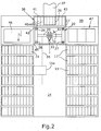
- the shelf warehouse which in the present case is a pharmacy warehouse has a support frame 10 in which all components are arranged. There are drawers in the support frame 10 11, which are movable on rollers 12 in guide rails 13. On both sides of a corridor 14 there is a row of Drawers available. Each of these drawers 11 can from its Be drawn out into the aisle 14 row.
- EP 0 734 975 B1 referenced.
- the drawers 11 contain shelves in the present case 15, which are not delimited from one another by transverse walls.
- Each shelf 15 has an inclined bottom 16 and one at right angles to this side wall 17 so that the Goods 18 added in a defined form in the angle formed being the largest commodity at 18 and the smallest commodity is designated 18a.
- the pull shelf 11 thus has a sawtooth shape Shelves.
- the transport device 20 is in the longitudinal direction of the aisle 14 traversable. This has a transport carriage 21 which Rails 22 of the support frame 10 out and above the drawers 11 is arranged. Runs over the transport carriage 21 a guide rail 23 attached to the support frame 10 whose opposite outer sides guide rollers 24 of the Attack transport carriage 21 to a side guide of the To effect transport carriage 21.
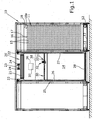
- a vertical guide 25 protrudes from the transport carriage 21 below. This consists of a pair of parallel left columns 26 and a pair of parallel right columns 27. The columns each Pairs are arranged one behind the other in the longitudinal direction of the aisle.
- the pillars 26 and 27 are through at their lower ends a cross strut 28 connected.
- the vertical guide 25 forms a rigid frame that only hangs at the top is, while the lower end has no guides that with the guides of the drawers 11 would collide.
- a vertical slide extends between the columns 26 and 27 30, which can be moved in a controlled manner in the vertical direction is.
- the vertical slide 30 is driven by (not shown) spindles arranged in or next to the columns 26,27 are and are driven synchronously.
- the pillars 26 and 27 are immediately adjacent to the row of Drawers, i.e. at the extreme ends of the width of the aisle 14. When the vertical slide 30 has moved to its uppermost position the passage 14 between the columns 26 and 27 is as Passage free for people.
- the vertical slide 30 forms a guide for a horizontal slide 31, across the aisle 14 on the vertical slide 30 is movable.
- the horizontal slide 31 carries a manipulator 32, one aligned in the longitudinal direction of the aisle Contains goods carrier 33.
- the horizontal slide 31 is in a certain Moved to the horizontal position that corresponds to the vertical target plane.
- the pull shelf 11 is moved so far into the aisle that that the shelf 15 to be controlled is also in the vertical target plane is in the aisle.
- the vertical slide 30 is moved vertically until the goods carrier 33 the height of shelf 15 has reached.
- the vertical target plane 35 is shown in the the manipulator 32 is moved on the vertical slide 30.
- the pull shelf 11a to be accessed is so far pulled out that the relevant shelf is in the target level 35 is located.
- the goods carrier 33 takes over the goods in to be explained from the shelf compartment. Then he drives Manipulator a receiving device 36 to which the goods is handed over. The goods are received by the receiving device 36 removed by a conveyor belt 37.
- the receiving device 36 is located over a goods transfer shelf 38, which is in an extension of the Ganges 14 is arranged and laterally in a parking position 39 can be moved in which it is the extension of the aisle releases.
- the transport device 20 is in the Shown transfer position in which the manipulator 32 the Receiving device 36 can reach to the goods to this to hand over.
- This transfer position is between the End of aisle 14 and the goods transfer rack 38.
- manipulator 32 also on the individual Access compartments 40 of the goods transfer shelf 38.
- the goods transfer shelf 38 has an input page 41 on the goods manually can be inserted, and an output side 42, in which the Manipulator 32 can intervene in a controlled manner.
- the goods transfer rack 38 is provided with a blind 43, that can be moved horizontally and is guided in such a way that it closes either the input side 41 or the output side 42. This is a direct access through a shelf compartment 40 not possible. In particular, it prevents a Person who intervenes in the input side 41 with one hand, is injured by the manipulator.
- shelf compartments 40 When using the goods transfer shelf 38, goods are defined in Shelf compartments 40 inserted manually.
- the manipulator 32 moves to the relevant shelf compartment, takes over the goods from this and introduces them into the shelf of a pull-out shelf. All Operations are carried out and saved under control.
- the warehouse computer then knows which drawers in which shelf compartment there is a certain commodity.
- goods can be removed manually from the warehouse become.
- the goods transfer shelf 38 is in the storage position 39 pushed so that through the transport device 20 the way into gear 14 is clear.
- the transport device 20 can be moved manually.
- the vertical slide 30 can be cranked up manually.
- the drawers in question 11 can be pulled out manually and the goods can be removed from it be removed.
- the function of the manipulator 32 is shown in FIGS. 4-7.
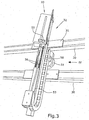
- the one on the vertical slide 30 is horizontally controlled, is located a horizontal bar 50 as the base part of the manipulator.
- the Beam 50 is relative to the horizontal slide by a rotary drive 51 31 pivotable about a vertical axis 52, so that he has the access position shown in the drawings can take in which it is directed to the shelf 15, or a delivery position in which it is rotated by 180 ° and in which the goods carrier 33 points away from the shelf compartment 15.
- the Goods carrier 33 is firmly attached to the bar 50. It exists from an angled sheet metal that conforms to the shape the shelf 15 is designed and positioned in front of this shelf can be.
- On the bar 50 is a driver 53 in Movable in the longitudinal direction.
- the bar is without pistons Pneumatic cylinder designed to move the driver 53.
- the driver 53 carries a rod device 54 made of two parallel rods that are slidable in the driver.
- On at the front ends of the bars is at least one suction pad 55 attached.
- a spring device 56 drives the suction pad 55 with the rod 54 in the front end position. This is because of it limited that a stop part 57 at the rear end the rod device 54 abuts against the driver 53.
- the stop part 57 also forms a marking part for one the sensor 58 attached to the driver 53. This detects when the stop member 57 leaves its front end position and is moved back.
- the driver is used to access the goods 60 53 advanced on the bar 50, the suction pad 55 against the goods hit 60 and pushes them in front of you without it the spring device 56 is compressed.
- Figure 6 shows the state that the goods 60 against an obstacle bumps, in the present case against the rear wall 61 of the shelf compartment 15. This makes the rod device 54 relative to that Carrier 53 moved backwards and the spring device 56 pressed together.
- the stop member 57 at the rear end of the Bar device 54 actuates the sensor 58 the suction gripper 55 switched on and this sucks on the Goods 60 solid. This ensures that a certain mechanical Contact pressure prevails through the spring device 56, so that the suction pad 55 can be fully effective.
- the driver 53 becomes on the bar 50 withdrawn while the suction pad 55 remains activated.
- the goods 60 are pulled onto the goods carrier 33.
- the horizontal slide 31 is moved into the middle position.
- the rotary drive 51 is then actuated to move the beam 50 swivel 180 ° into the delivery position.
- the vertical slide 30 is raised to the level of the receiving device 36 and at the same time the horizontal slide 31 in the for drove the goods in the required transverse position. If the Receiving device 36 is reached, the driver 53 the goods 60 down from the goods carrier 33 without the Suction pad 55 is activated.
Landscapes
- Engineering & Computer Science (AREA)
- Mechanical Engineering (AREA)
- Warehouses Or Storage Devices (AREA)
- Vending Machines For Individual Products (AREA)
- Manipulator (AREA)
Abstract
Description
- Fig. 1:
- eine schematische Stirnansicht des Regallagers mit Blickrichtung in den Gang hinein,
- Fig. 2:
- eine schematische Draufsicht des Regallagers,
- Fig. 3:
- eine perspektivische Darstellung des Manipulators aus Richtung des Pfeils III von Figur 1,
- Fig. 4:
- eine Seitenansicht des Manipulators aus Richtung des Pfeils IV von Figur 3 in der Grundstellung,
- Fig. 5:
- den Manipulator, der in ein Regalfach hineinfährt,
- Fig. 6:
- das Ergreifen der Ware durch den Sauggreifer nach dem Vorschieben gegen die Rückwand des Regalfachs, und
- Fig. 7:
- das Herausziehen der Ware auf den Warenträger durch den Sauggreifer.
Claims (16)
- Regallager mit Ziehregalen, die in einen Gang (14) hinein bewegbar sind, in welchem eine einen Manipulator (32) tragende Transportvorrichtung (20) fährt, wobei die Transportvorrichtung (20) einen längs des Ganges (14) geführten Transportschlitten (21) aufweist, von dem eine Vertikalführung (25) für einen Vertikalschlitten (30) frei absteht,
dadurch gekennzeichnet, dass die Vertikalführung (25) mindestens zwei seitlich angeordnete Säulen (26,27) aufweist, zwischen denen sich ein Durchgang befindet und dass der Vertikalschlitten (30) entlang der Säulen (26,27) beidendig geführt ist. - Regallager nach Anspruch 1, dadurch gekennzeichnet, dass die Säulen (26,27) an ihren freien Enden durch eine Querstrebe (28) verbunden sind.
- Regallager nach Anspruch 1 oder 2, dadurch gekennzeichnet, dass die Vertikalführung (25) ein Gestell aus vier Säulen (26,27) aufweist, an denen der Vertikalschlitten (30) geführt ist.
- Regallager nach einem der Ansprüche 1 - 3, dadurch gekennzeichnet, dass der Manipulator (32) auf dem Vertikalschlitten (30) um eine vertikale Achse (52) drehbar ist, um einen Warenträger (33) entweder in die Zugriffsrichtung oder in die Abgaberichtung zu bringen.
- Regallager nach einem der Ansprüche 1 - 4, dadurch gekennzeichnet, dass die Säulen (26,27) synchron angetriebene Spindeln für den Antrieb des Vertikalschlittens (30) aufweisen.
- Regallager nach einem der Ansprüche 1 - 5, dadurch gekennzeichnet, dass eine Aufnahmevorrichtung (36), an die der Manipulator (32) Waren übergibt, in Verlängerung des Ganges (14) in einer Höhe im oberen Bereich des Weges des Vertikalschlittens (30) angeordnet ist.
- Regallager nach einem der Ansprüche 1 - 6, dadurch gekennzeichnet, dass ein Warenübergaberegal (38), das mindestens zeitweise in Verlängerung des Ganges (14) positionierbar ist, auf der dem Gang (14) abgewandten Seite als Eingabeseite (41) und auf der dem Gang zugewandten Seite als Ausgabeseite (42) ausgebildet ist.
- Regallager nach Anspruch 7, dadurch gekennzeichnet, dass zwischen dem Ende des Ganges (14) und dem Warenübergaberegal (38) eine Übergabeposition (45) für die Transportvorrichtung (20) vorgesehen ist.
- Regallager nach Anspruch 7 oder 8, dadurch gekennzeichnet, dass eine Abstellposition (39) für das Warenübergaberegal (38) in Verlängerung einer Reihe von Ziehregalen (11) vorgesehen ist.
- Regallager nach einem der Ansprüche 7 - 9, dadurch gekennzeichnet, dass das Warenübergaberegal (38) eine Jalousie (43) aufweist, die in einer ersten Position die Eingabeseite (41) verschließt und in einer zweiten Position die Ausgabeseite (42) verschließt.
- Regallager nach den Ansprüchen 6 und 7, dadurch gekennzeichnet, dass die Aufnahmevorrichtung (36) über der Betriebsposition des Warenübergaberegals (38) angeordnet ist, derart, dass der Manipulator (32) die Waren (60) bei hochgefahrenem Vertikalschlitten (30) über dem Warenübergaberegal (38) in die Aufnahmevorrichtung (36) entlässt.
- Regallager mit Regalen, die Regalfächer (15) enthalten, und einem Manipulator (32) , der einen vor einem Regalfach positionierbaren Warenträger (33) und einen die Waren (60) auf den Warenträger (33) ziehenden Sauggreifer (55) aufweist,
dadurch gekennzeichnet, dass entlang eines den Warenträger (33) tragenden Balkens (50) ein den Sauggreifer (55) tragender Mitnehmer (53) bewegbar ist, und dass ein Sensor (58) vorgesehen ist, der feststellt, wenn der Sauggreifer (55) die Ware (60) gegen einen Widerstand im Regalfach (15) drückt und dann die Rückwärtsbewegung des Mitnehmers (53) einleitet, wodurch der eingeschaltete Sauggreifer (55) die Ware (60) aus dem Regalfach (15) auf den Warenträger (33) zieht. - Regallager nach Anspruch 12, dadurch gekennzeichnet, dass der Balken (50) an einem Horizontalschlitten (31) um eine vertikale Achse (52) schwenkbar ist.
- Regallager nach Anspruch 12 oder 13, dadurch gekennzeichnet, dass der Warenträger (33) an dem Balken (50) starr befestigt ist.
- Regallager nach einem der Ansprüche 12 - 14, dadurch gekennzeichnet, dass der Sauggreifer (55) an einer in Bezug auf den Mitnehmer (53) verschiebbaren, nach vorne vorgespannten Stangenvorrichtüng (54) befestigt ist und dass der Sensor (58) eine Verschiebung der Stangenvorrichtung (54) in Bezug auf den Mitnehmer (53) feststellt.
- Regallager nach einem der Ansprüche 12 - 15, dadurch gekennzeichnet, dass der Balken (50) auf einem Horizontalschlitten (31) angeordnet ist, der entlang eines Vertikalschlittens (30) quer zu einem Gang (14) gesteuert verfahrbar ist.
Priority Applications (1)
| Application Number | Priority Date | Filing Date | Title |
|---|---|---|---|
| EP05108897A EP1642850B1 (de) | 2002-10-09 | 2003-10-04 | Regallager mit Manipulator mit Sauggreifer |
Applications Claiming Priority (2)
| Application Number | Priority Date | Filing Date | Title |
|---|---|---|---|
| DE20215479U DE20215479U1 (de) | 2002-10-09 | 2002-10-09 | Regallager mit Ziehregalen |
| DE20215479U | 2002-10-09 |
Related Child Applications (1)
| Application Number | Title | Priority Date | Filing Date |
|---|---|---|---|
| EP05108897A Division EP1642850B1 (de) | 2002-10-09 | 2003-10-04 | Regallager mit Manipulator mit Sauggreifer |
Publications (3)
| Publication Number | Publication Date |
|---|---|
| EP1407984A2 true EP1407984A2 (de) | 2004-04-14 |
| EP1407984A3 EP1407984A3 (de) | 2004-05-06 |
| EP1407984B1 EP1407984B1 (de) | 2006-03-01 |
Family
ID=31984527
Family Applications (2)
| Application Number | Title | Priority Date | Filing Date |
|---|---|---|---|
| EP05108897A Expired - Lifetime EP1642850B1 (de) | 2002-10-09 | 2003-10-04 | Regallager mit Manipulator mit Sauggreifer |
| EP03022344A Expired - Lifetime EP1407984B1 (de) | 2002-10-09 | 2003-10-04 | Regallager mit Ziehregalen |
Family Applications Before (1)
| Application Number | Title | Priority Date | Filing Date |
|---|---|---|---|
| EP05108897A Expired - Lifetime EP1642850B1 (de) | 2002-10-09 | 2003-10-04 | Regallager mit Manipulator mit Sauggreifer |
Country Status (5)
| Country | Link |
|---|---|
| EP (2) | EP1642850B1 (de) |
| AT (2) | ATE388103T1 (de) |
| DE (3) | DE20215479U1 (de) |
| ES (2) | ES2303191T3 (de) |
| PT (1) | PT1642850E (de) |
Cited By (3)
| Publication number | Priority date | Publication date | Assignee | Title |
|---|---|---|---|---|
| EP1900654A1 (de) * | 2006-09-12 | 2008-03-19 | GEBR. WILLACH GmbH | Warenannahmeautomat |
| DE202007009400U1 (de) * | 2007-07-04 | 2008-11-13 | Gebr. Willach Gmbh | Rechnergestütztes Lagersystem |
| EP2040230A3 (de) * | 2007-09-19 | 2010-03-17 | Gebr. Willach GmbH | Automatisches Warenlager |
Families Citing this family (6)
| Publication number | Priority date | Publication date | Assignee | Title |
|---|---|---|---|---|
| DE102006007359A1 (de) | 2006-02-15 | 2007-08-23 | Gollmann Kommissioniersysteme Gmbh | Verfahren einer modifizierten, automatischen, dreidimensionalen Lagerhaltung, insbesondere für Apotheken und Einrichtung zur Durchführung des Verfahrens |
| DE202006014375U1 (de) * | 2006-09-20 | 2008-02-07 | Gebr. Willach Gmbh | Warenlager |
| DE202007009399U1 (de) | 2007-07-04 | 2007-09-27 | Gebr. Willach Gmbh | Kombiniertes Warenlager |
| EP2119642A1 (de) * | 2008-05-02 | 2009-11-18 | Rowa Automatisierungssysteme GmbH | Verfahren zum Lagern einer Vielzahl zylindrischer Behälter in einem automatisierten Regallager und dabei verwendeter Träger |
| FR2949222B1 (fr) * | 2009-08-20 | 2011-10-21 | Intecum | Systeme de stockage et de delivrance de boites parallelepipediques, en particulier de boites de medicament |
| CN109650061B (zh) * | 2019-03-05 | 2024-01-02 | 唐山晟群科技有限公司 | 气动取药机械手 |
Family Cites Families (15)
| Publication number | Priority date | Publication date | Assignee | Title |
|---|---|---|---|---|
| CH532517A (it) * | 1970-11-30 | 1973-01-15 | Doriguzzi Ezio | Magazzino a scaffali meccanizzato, atto a consentire la movimentazione delle merci immagazzinate |
| US3820667A (en) * | 1972-12-12 | 1974-06-28 | Materials Management Syst Inc | Article handling machine |
| EP0116126A1 (de) * | 1982-12-21 | 1984-08-22 | J. Sandt AG | Regal mit wenigstens einem Regalbediengerät |
| DE3435679A1 (de) * | 1984-09-28 | 1986-04-03 | Jungheinrich Unternehmensverwaltung Kg, 2000 Hamburg | Verfahren zur ein- und ausstapelung von transporteinheiten in eine vielzahl von ablagestellen und regal-anlage zur durchfuehrung des verfahrens |
| US4789295A (en) * | 1985-02-26 | 1988-12-06 | International Business Machines Corp. | Article manipulator for robot |
| DE3530188A1 (de) * | 1985-08-23 | 1987-03-05 | Johannes Zidek | Selbstverleiher fuer elektronisch identifizierbare gegenstaende, insbesondere videobandkassetten |
| DE4001937A1 (de) * | 1990-01-24 | 1991-07-25 | Antriebs Steuerungstech Ges | Handhabungsvorrichtung mit einem sauggreifer und verfahren zum handhaben und ueberpruefen von fluiddurchstroemten bauteilen |
| CH680212A5 (en) * | 1990-03-16 | 1992-07-15 | Fritschi Ag Hugo | Shelf service equipment for high level shelf storage - enables bundles to circulate on intermediate storage conveyor which allows access to other bundles behind them |
| DE4128556A1 (de) * | 1991-08-28 | 1993-03-04 | Grau Gmbh & Co Holdingges | Datentraegerarchivsystem |
| DE4306469A1 (de) * | 1993-03-02 | 1994-09-08 | Lt Engineering Gisin & Urban | Regallager |
| DE4311146A1 (de) * | 1993-04-05 | 1994-10-06 | Noell Gmbh | Schnellumschlagterminal |
| DE19509951C2 (de) * | 1995-03-18 | 1997-03-13 | Rudolf M Dipl Ing Wagner | Vorrichtung zum unsortierten Lagern von Waren oder sonstigen Gegenständen |
| DE29505214U1 (de) * | 1995-03-28 | 1996-08-01 | Gebr. Willach GmbH, 53809 Ruppichteroth | Regallager mit Ziehregalen |
| DE29722170U1 (de) * | 1997-12-16 | 1999-04-15 | Gebr. Willach GmbH, 53809 Ruppichteroth | Regallager |
| DE29817215U1 (de) * | 1998-09-29 | 1999-04-01 | Beils, Dirk Rolf, 56727 Mayen | Aufgabestation für eine automatisierte Lageranlage |
-
2002
- 2002-10-09 DE DE20215479U patent/DE20215479U1/de not_active Expired - Lifetime
-
2003
- 2003-10-04 PT PT05108897T patent/PT1642850E/pt unknown
- 2003-10-04 DE DE50302510T patent/DE50302510D1/de not_active Expired - Lifetime
- 2003-10-04 ES ES05108897T patent/ES2303191T3/es not_active Expired - Lifetime
- 2003-10-04 AT AT05108897T patent/ATE388103T1/de not_active IP Right Cessation
- 2003-10-04 AT AT03022344T patent/ATE318779T1/de not_active IP Right Cessation
- 2003-10-04 EP EP05108897A patent/EP1642850B1/de not_active Expired - Lifetime
- 2003-10-04 EP EP03022344A patent/EP1407984B1/de not_active Expired - Lifetime
- 2003-10-04 ES ES03022344T patent/ES2258689T3/es not_active Expired - Lifetime
- 2003-10-04 DE DE50309350T patent/DE50309350D1/de not_active Expired - Lifetime
Cited By (3)
| Publication number | Priority date | Publication date | Assignee | Title |
|---|---|---|---|---|
| EP1900654A1 (de) * | 2006-09-12 | 2008-03-19 | GEBR. WILLACH GmbH | Warenannahmeautomat |
| DE202007009400U1 (de) * | 2007-07-04 | 2008-11-13 | Gebr. Willach Gmbh | Rechnergestütztes Lagersystem |
| EP2040230A3 (de) * | 2007-09-19 | 2010-03-17 | Gebr. Willach GmbH | Automatisches Warenlager |
Also Published As
| Publication number | Publication date |
|---|---|
| DE50302510D1 (de) | 2006-04-27 |
| ATE388103T1 (de) | 2008-03-15 |
| ES2303191T3 (es) | 2008-08-01 |
| EP1407984A3 (de) | 2004-05-06 |
| ATE318779T1 (de) | 2006-03-15 |
| DE50309350D1 (de) | 2008-04-17 |
| ES2258689T3 (es) | 2006-09-01 |
| EP1642850A1 (de) | 2006-04-05 |
| PT1642850E (pt) | 2008-04-15 |
| EP1407984B1 (de) | 2006-03-01 |
| DE20215479U1 (de) | 2004-03-04 |
| EP1642850B1 (de) | 2008-03-05 |
Similar Documents
| Publication | Publication Date | Title |
|---|---|---|
| AT510537A1 (de) | Verfahren zum einlagern von waren sowie vorrichtung dazu | |
| DE4002360A1 (de) | Hin- und hergehender foerderer mit von diesem trennbarer antriebsvorrichtung | |
| DE9103197U1 (de) | Regalbediengerät für Hochregallager | |
| EP1423314B1 (de) | Regallager mit schiebern in den regalfächern | |
| DE1802410C3 (de) | Fahrbares Regalförderzeug | |
| EP1407984B1 (de) | Regallager mit Ziehregalen | |
| DE69006457T2 (de) | Vorrichtung zum Be- und/oder Entladen der Regale eines Gefriertrocknungsraumes. | |
| DE3514932A1 (de) | Mechanischer schrank | |
| AT402194B (de) | Verfahren und anlage zum sortieren von zuschnitten | |
| EP0734975B1 (de) | Regallager mit Ziehregalen | |
| DE2648630C2 (de) | Durchlauflager | |
| EP0798238B1 (de) | Lagersystem für Langgutpaletten | |
| EP0470538B1 (de) | Regal zur Lagerung von Abstandhalter-Profilen für Isolierglasscheiben | |
| EP1862405B1 (de) | Verfahren zum Greifen eines Stückgutes mittels Greifelementen einer Ein- und Auslagervorrichtung und Vorrichtung hierfür | |
| DE102004024478B4 (de) | Regallager mit herausnehmbaren Trenner bei den Regalböden | |
| EP1218266B1 (de) | Bediengerät für ein regallager | |
| AT404821B (de) | Speicherregal | |
| DE8233671U1 (de) | Einrichtung zur lagerung von materialien, insbesondere langgut | |
| DE102005035262A1 (de) | Regallager mit Eingabestation | |
| CH672111A5 (en) | Mechanical filing system using paternoster store | |
| DE4435085A1 (de) | Vorrichtung und Verfahren zum Aufbewahren von Gegenständen | |
| DE2163101C3 (de) | Einrichtung zur Lagerung von stangenförmigem Material und zur selbsttätigen Versorgung einer programmgesteuerten Trennmaschine damit | |
| DE2515429A1 (de) | Stapelkran | |
| DE2449805C3 (de) | Durchlaufregallager-Anlage | |
| DE2231495C3 (de) | Anlage zum selbsttätigen Beladen von ortsfesten oder ortsbeweglichen La- ' deflächen, insbesondere von Ladeflächen von offenen oder geschlossenen Lastkraftwagen, mit Stückgütern, insbesondere Säcken |
Legal Events
| Date | Code | Title | Description |
|---|---|---|---|
| PUAI | Public reference made under article 153(3) epc to a published international application that has entered the european phase |
Free format text: ORIGINAL CODE: 0009012 |
|
| PUAL | Search report despatched |
Free format text: ORIGINAL CODE: 0009013 |
|
| AK | Designated contracting states |
Kind code of ref document: A2 Designated state(s): AT BE BG CH CY CZ DE DK EE ES FI FR GB GR HU IE IT LI LU MC NL PT RO SE SI SK TR |
|
| AX | Request for extension of the european patent |
Extension state: AL LT LV MK |
|
| AK | Designated contracting states |
Kind code of ref document: A3 Designated state(s): AT BE BG CH CY CZ DE DK EE ES FI FR GB GR HU IE IT LI LU MC NL PT RO SE SI SK TR |
|
| AX | Request for extension of the european patent |
Extension state: AL LT LV MK |
|
| 17P | Request for examination filed |
Effective date: 20041027 |
|
| AKX | Designation fees paid |
Designated state(s): AT BE BG CH CY CZ DE DK EE ES FI FR GB GR HU IE IT LI LU MC NL PT RO SE SI SK TR |
|
| 17Q | First examination report despatched |
Effective date: 20050103 |
|
| GRAP | Despatch of communication of intention to grant a patent |
Free format text: ORIGINAL CODE: EPIDOSNIGR1 |
|
| GRAS | Grant fee paid |
Free format text: ORIGINAL CODE: EPIDOSNIGR3 |
|
| GRAA | (expected) grant |
Free format text: ORIGINAL CODE: 0009210 |
|
| AK | Designated contracting states |
Kind code of ref document: B1 Designated state(s): AT BE BG CH CY CZ DE DK EE ES FI FR GB GR HU IE IT LI LU MC NL PT RO SE SI SK TR |
|
| PG25 | Lapsed in a contracting state [announced via postgrant information from national office to epo] |
Ref country code: IT Free format text: LAPSE BECAUSE OF FAILURE TO SUBMIT A TRANSLATION OF THE DESCRIPTION OR TO PAY THE FEE WITHIN THE PRESCRIBED TIME-LIMIT;WARNING: LAPSES OF ITALIAN PATENTS WITH EFFECTIVE DATE BEFORE 2007 MAY HAVE OCCURRED AT ANY TIME BEFORE 2007. THE CORRECT EFFECTIVE DATE MAY BE DIFFERENT FROM THE ONE RECORDED. Effective date: 20060301 Ref country code: IE Free format text: LAPSE BECAUSE OF FAILURE TO SUBMIT A TRANSLATION OF THE DESCRIPTION OR TO PAY THE FEE WITHIN THE PRESCRIBED TIME-LIMIT Effective date: 20060301 Ref country code: FI Free format text: LAPSE BECAUSE OF FAILURE TO SUBMIT A TRANSLATION OF THE DESCRIPTION OR TO PAY THE FEE WITHIN THE PRESCRIBED TIME-LIMIT Effective date: 20060301 Ref country code: RO Free format text: LAPSE BECAUSE OF FAILURE TO SUBMIT A TRANSLATION OF THE DESCRIPTION OR TO PAY THE FEE WITHIN THE PRESCRIBED TIME-LIMIT Effective date: 20060301 Ref country code: SI Free format text: LAPSE BECAUSE OF FAILURE TO SUBMIT A TRANSLATION OF THE DESCRIPTION OR TO PAY THE FEE WITHIN THE PRESCRIBED TIME-LIMIT Effective date: 20060301 Ref country code: SK Free format text: LAPSE BECAUSE OF FAILURE TO SUBMIT A TRANSLATION OF THE DESCRIPTION OR TO PAY THE FEE WITHIN THE PRESCRIBED TIME-LIMIT Effective date: 20060301 |
|
| REG | Reference to a national code |
Ref country code: GB Ref legal event code: FG4D Free format text: NOT ENGLISH |
|
| REG | Reference to a national code |
Ref country code: CH Ref legal event code: EP Ref country code: CH Ref legal event code: NV Representative=s name: ISLER & PEDRAZZINI AG |
|
| REG | Reference to a national code |
Ref country code: IE Ref legal event code: FG4D Free format text: LANGUAGE OF EP DOCUMENT: GERMAN |
|
| REF | Corresponds to: |
Ref document number: 50302510 Country of ref document: DE Date of ref document: 20060427 Kind code of ref document: P |
|
| PG25 | Lapsed in a contracting state [announced via postgrant information from national office to epo] |
Ref country code: DK Free format text: LAPSE BECAUSE OF FAILURE TO SUBMIT A TRANSLATION OF THE DESCRIPTION OR TO PAY THE FEE WITHIN THE PRESCRIBED TIME-LIMIT Effective date: 20060601 Ref country code: BG Free format text: LAPSE BECAUSE OF FAILURE TO SUBMIT A TRANSLATION OF THE DESCRIPTION OR TO PAY THE FEE WITHIN THE PRESCRIBED TIME-LIMIT Effective date: 20060601 |
|
| REG | Reference to a national code |
Ref country code: SE Ref legal event code: TRGR |
|
| GBT | Gb: translation of ep patent filed (gb section 77(6)(a)/1977) |
Effective date: 20060518 |
|
| ET | Fr: translation filed | ||
| REG | Reference to a national code |
Ref country code: ES Ref legal event code: FG2A Ref document number: 2258689 Country of ref document: ES Kind code of ref document: T3 |
|
| REG | Reference to a national code |
Ref country code: IE Ref legal event code: FD4D |
|
| PG25 | Lapsed in a contracting state [announced via postgrant information from national office to epo] |
Ref country code: MC Free format text: LAPSE BECAUSE OF NON-PAYMENT OF DUE FEES Effective date: 20061031 |
|
| PLBE | No opposition filed within time limit |
Free format text: ORIGINAL CODE: 0009261 |
|
| STAA | Information on the status of an ep patent application or granted ep patent |
Free format text: STATUS: NO OPPOSITION FILED WITHIN TIME LIMIT |
|
| 26N | No opposition filed |
Effective date: 20061204 |
|
| REG | Reference to a national code |
Ref country code: CH Ref legal event code: PCAR Free format text: ISLER & PEDRAZZINI AG;POSTFACH 1772;8027 ZUERICH (CH) |
|
| PG25 | Lapsed in a contracting state [announced via postgrant information from national office to epo] |
Ref country code: CZ Free format text: LAPSE BECAUSE OF FAILURE TO SUBMIT A TRANSLATION OF THE DESCRIPTION OR TO PAY THE FEE WITHIN THE PRESCRIBED TIME-LIMIT Effective date: 20060301 Ref country code: GR Free format text: LAPSE BECAUSE OF FAILURE TO SUBMIT A TRANSLATION OF THE DESCRIPTION OR TO PAY THE FEE WITHIN THE PRESCRIBED TIME-LIMIT Effective date: 20060602 |
|
| PG25 | Lapsed in a contracting state [announced via postgrant information from national office to epo] |
Ref country code: EE Free format text: LAPSE BECAUSE OF FAILURE TO SUBMIT A TRANSLATION OF THE DESCRIPTION OR TO PAY THE FEE WITHIN THE PRESCRIBED TIME-LIMIT Effective date: 20060301 |
|
| PG25 | Lapsed in a contracting state [announced via postgrant information from national office to epo] |
Ref country code: TR Free format text: LAPSE BECAUSE OF FAILURE TO SUBMIT A TRANSLATION OF THE DESCRIPTION OR TO PAY THE FEE WITHIN THE PRESCRIBED TIME-LIMIT Effective date: 20060301 Ref country code: LU Free format text: LAPSE BECAUSE OF NON-PAYMENT OF DUE FEES Effective date: 20061004 Ref country code: HU Free format text: LAPSE BECAUSE OF FAILURE TO SUBMIT A TRANSLATION OF THE DESCRIPTION OR TO PAY THE FEE WITHIN THE PRESCRIBED TIME-LIMIT Effective date: 20060902 |
|
| PGFP | Annual fee paid to national office [announced via postgrant information from national office to epo] |
Ref country code: PT Payment date: 20080924 Year of fee payment: 6 |
|
| PG25 | Lapsed in a contracting state [announced via postgrant information from national office to epo] |
Ref country code: CY Free format text: LAPSE BECAUSE OF FAILURE TO SUBMIT A TRANSLATION OF THE DESCRIPTION OR TO PAY THE FEE WITHIN THE PRESCRIBED TIME-LIMIT Effective date: 20060301 |
|
| PGFP | Annual fee paid to national office [announced via postgrant information from national office to epo] |
Ref country code: NL Payment date: 20081023 Year of fee payment: 6 |
|
| PGFP | Annual fee paid to national office [announced via postgrant information from national office to epo] |
Ref country code: CH Payment date: 20081027 Year of fee payment: 6 |
|
| PGFP | Annual fee paid to national office [announced via postgrant information from national office to epo] |
Ref country code: AT Payment date: 20081023 Year of fee payment: 6 Ref country code: ES Payment date: 20081027 Year of fee payment: 6 |
|
| PGFP | Annual fee paid to national office [announced via postgrant information from national office to epo] |
Ref country code: SE Payment date: 20081027 Year of fee payment: 6 Ref country code: IT Payment date: 20081027 Year of fee payment: 6 Ref country code: BE Payment date: 20081024 Year of fee payment: 6 |
|
| PGFP | Annual fee paid to national office [announced via postgrant information from national office to epo] |
Ref country code: FR Payment date: 20081021 Year of fee payment: 6 |
|
| PGFP | Annual fee paid to national office [announced via postgrant information from national office to epo] |
Ref country code: GB Payment date: 20081024 Year of fee payment: 6 |
|
| REG | Reference to a national code |
Ref country code: PT Ref legal event code: MM4A Free format text: LAPSE DUE TO NON-PAYMENT OF FEES Effective date: 20100405 |
|
| BERE | Be: lapsed |
Owner name: GEBR. *WILLACH G.M.B.H. Effective date: 20091031 |
|
| REG | Reference to a national code |
Ref country code: NL Ref legal event code: V1 Effective date: 20100501 |
|
| REG | Reference to a national code |
Ref country code: CH Ref legal event code: PL |
|
| EUG | Se: european patent has lapsed | ||
| REG | Reference to a national code |
Ref country code: FR Ref legal event code: ST Effective date: 20100630 |
|
| PG25 | Lapsed in a contracting state [announced via postgrant information from national office to epo] |
Ref country code: NL Free format text: LAPSE BECAUSE OF NON-PAYMENT OF DUE FEES Effective date: 20100501 Ref country code: PT Free format text: LAPSE BECAUSE OF NON-PAYMENT OF DUE FEES Effective date: 20100405 Ref country code: FR Free format text: LAPSE BECAUSE OF NON-PAYMENT OF DUE FEES Effective date: 20091102 |
|
| PG25 | Lapsed in a contracting state [announced via postgrant information from national office to epo] |
Ref country code: AT Free format text: LAPSE BECAUSE OF NON-PAYMENT OF DUE FEES Effective date: 20091004 |
|
| PG25 | Lapsed in a contracting state [announced via postgrant information from national office to epo] |
Ref country code: BE Free format text: LAPSE BECAUSE OF NON-PAYMENT OF DUE FEES Effective date: 20091031 Ref country code: CH Free format text: LAPSE BECAUSE OF NON-PAYMENT OF DUE FEES Effective date: 20091031 Ref country code: LI Free format text: LAPSE BECAUSE OF NON-PAYMENT OF DUE FEES Effective date: 20091031 |
|
| PG25 | Lapsed in a contracting state [announced via postgrant information from national office to epo] |
Ref country code: GB Free format text: LAPSE BECAUSE OF NON-PAYMENT OF DUE FEES Effective date: 20091004 |
|
| REG | Reference to a national code |
Ref country code: ES Ref legal event code: FD2A Effective date: 20110307 |
|
| PG25 | Lapsed in a contracting state [announced via postgrant information from national office to epo] |
Ref country code: IT Free format text: LAPSE BECAUSE OF NON-PAYMENT OF DUE FEES Effective date: 20091004 |
|
| PG25 | Lapsed in a contracting state [announced via postgrant information from national office to epo] |
Ref country code: SE Free format text: LAPSE BECAUSE OF NON-PAYMENT OF DUE FEES Effective date: 20091005 |
|
| PG25 | Lapsed in a contracting state [announced via postgrant information from national office to epo] |
Ref country code: ES Free format text: LAPSE BECAUSE OF NON-PAYMENT OF DUE FEES Effective date: 20110304 |
|
| PG25 | Lapsed in a contracting state [announced via postgrant information from national office to epo] |
Ref country code: ES Free format text: LAPSE BECAUSE OF NON-PAYMENT OF DUE FEES Effective date: 20091005 |
|
| PGFP | Annual fee paid to national office [announced via postgrant information from national office to epo] |
Ref country code: DE Payment date: 20191031 Year of fee payment: 17 |
|
| REG | Reference to a national code |
Ref country code: DE Ref legal event code: R119 Ref document number: 50302510 Country of ref document: DE |
|
| PG25 | Lapsed in a contracting state [announced via postgrant information from national office to epo] |
Ref country code: DE Free format text: LAPSE BECAUSE OF NON-PAYMENT OF DUE FEES Effective date: 20210501 |