EP1407992A1 - Dispositif de mise en place contrôlée de produits dans un récipient, et un récipient et un véhicule de transport - Google Patents
Dispositif de mise en place contrôlée de produits dans un récipient, et un récipient et un véhicule de transport Download PDFInfo
- Publication number
- EP1407992A1 EP1407992A1 EP20020079207 EP02079207A EP1407992A1 EP 1407992 A1 EP1407992 A1 EP 1407992A1 EP 20020079207 EP20020079207 EP 20020079207 EP 02079207 A EP02079207 A EP 02079207A EP 1407992 A1 EP1407992 A1 EP 1407992A1
- Authority
- EP
- European Patent Office
- Prior art keywords
- container
- product
- products
- loading
- transport path
- Prior art date
- Legal status (The legal status is an assumption and is not a legal conclusion. Google has not performed a legal analysis and makes no representation as to the accuracy of the status listed.)
- Granted
Links
- 238000006073 displacement reaction Methods 0.000 claims abstract description 6
- 238000009826 distribution Methods 0.000 description 4
- 238000012545 processing Methods 0.000 description 4
- 230000007257 malfunction Effects 0.000 description 3
- 238000000034 method Methods 0.000 description 2
- 238000012856 packing Methods 0.000 description 2
- 238000007599 discharging Methods 0.000 description 1
- 239000002783 friction material Substances 0.000 description 1
- 238000007689 inspection Methods 0.000 description 1
- 238000009434 installation Methods 0.000 description 1
- 238000004519 manufacturing process Methods 0.000 description 1
- 238000012544 monitoring process Methods 0.000 description 1
- 230000003287 optical effect Effects 0.000 description 1
- 238000004806 packaging method and process Methods 0.000 description 1
- 238000005192 partition Methods 0.000 description 1
- 238000005096 rolling process Methods 0.000 description 1
- 235000015067 sauces Nutrition 0.000 description 1
- 235000011888 snacks Nutrition 0.000 description 1
- 235000014347 soups Nutrition 0.000 description 1
- 238000013519 translation Methods 0.000 description 1
Images


Classifications
-
- B—PERFORMING OPERATIONS; TRANSPORTING
- B65—CONVEYING; PACKING; STORING; HANDLING THIN OR FILAMENTARY MATERIAL
- B65D—CONTAINERS FOR STORAGE OR TRANSPORT OF ARTICLES OR MATERIALS, e.g. BAGS, BARRELS, BOTTLES, BOXES, CANS, CARTONS, CRATES, DRUMS, JARS, TANKS, HOPPERS, FORWARDING CONTAINERS; ACCESSORIES, CLOSURES, OR FITTINGS THEREFOR; PACKAGING ELEMENTS; PACKAGES
- B65D90/00—Component parts, details or accessories for large containers
- B65D90/004—Contents retaining means
- B65D90/0053—Contents retaining means fixed on the side wall of the container
-
- B—PERFORMING OPERATIONS; TRANSPORTING
- B60—VEHICLES IN GENERAL
- B60P—VEHICLES ADAPTED FOR LOAD TRANSPORTATION OR TO TRANSPORT, TO CARRY, OR TO COMPRISE SPECIAL LOADS OR OBJECTS
- B60P7/00—Securing or covering of load on vehicles
- B60P7/06—Securing of load
- B60P7/065—Securing of load by pressurizing or creating a vacuum in a bag, cover or the like
-
- B—PERFORMING OPERATIONS; TRANSPORTING
- B62—LAND VEHICLES FOR TRAVELLING OTHERWISE THAN ON RAILS
- B62B—HAND-PROPELLED VEHICLES, e.g. HAND CARTS OR PERAMBULATORS; SLEDGES
- B62B3/00—Hand carts having more than one axis carrying transport wheels; Steering devices therefor; Equipment therefor
- B62B3/002—Hand carts having more than one axis carrying transport wheels; Steering devices therefor; Equipment therefor characterised by a rectangular shape, involving sidewalls or racks
-
- B—PERFORMING OPERATIONS; TRANSPORTING
- B62—LAND VEHICLES FOR TRAVELLING OTHERWISE THAN ON RAILS
- B62B—HAND-PROPELLED VEHICLES, e.g. HAND CARTS OR PERAMBULATORS; SLEDGES
- B62B3/00—Hand carts having more than one axis carrying transport wheels; Steering devices therefor; Equipment therefor
- B62B3/04—Hand carts having more than one axis carrying transport wheels; Steering devices therefor; Equipment therefor involving means for grappling or securing in place objects to be carried; Loading or unloading equipment
-
- B—PERFORMING OPERATIONS; TRANSPORTING
- B65—CONVEYING; PACKING; STORING; HANDLING THIN OR FILAMENTARY MATERIAL
- B65G—TRANSPORT OR STORAGE DEVICES, e.g. CONVEYORS FOR LOADING OR TIPPING, SHOP CONVEYOR SYSTEMS OR PNEUMATIC TUBE CONVEYORS
- B65G61/00—Use of pick-up or transfer devices or of manipulators for stacking or de-stacking articles not otherwise provided for
-
- B—PERFORMING OPERATIONS; TRANSPORTING
- B62—LAND VEHICLES FOR TRAVELLING OTHERWISE THAN ON RAILS
- B62B—HAND-PROPELLED VEHICLES, e.g. HAND CARTS OR PERAMBULATORS; SLEDGES
- B62B2203/00—Grasping, holding, supporting the objects
-
- B—PERFORMING OPERATIONS; TRANSPORTING
- B65—CONVEYING; PACKING; STORING; HANDLING THIN OR FILAMENTARY MATERIAL
- B65D—CONTAINERS FOR STORAGE OR TRANSPORT OF ARTICLES OR MATERIALS, e.g. BAGS, BARRELS, BOTTLES, BOXES, CANS, CARTONS, CRATES, DRUMS, JARS, TANKS, HOPPERS, FORWARDING CONTAINERS; ACCESSORIES, CLOSURES, OR FITTINGS THEREFOR; PACKAGING ELEMENTS; PACKAGES
- B65D2590/00—Component parts, details or accessories for large containers
- B65D2590/0041—Contents retaining means
- B65D2590/005—Contents retaining means adaptable to the size of the transport goods
Definitions
- the present invention relates to a device for the controlled placing of products in a container, comprising a transport path for a supply of products, a loading station close to an end of the transport path to receive the container, which loading station is provided with loading means for controlled placing in the container of products supplied by the conveyor belt.
- Such a device finds particular application in warehouses and distribution centres, wherein large numbers of articles sometimes have to be packed together in one container before the products are transported.
- This transport may be internal, for instance from a warehouse to a manufacturing department, or external, wherein the goods are moved to an external destination by road or otherwise.
- Much of this packing work has heretofore taken place by hand.
- diverse mechanical solutions have already been proposed, most of which use a robot arm to pick up the products from the transport path and place them in the container. This usually involves the packing of a flow, which may or may not be constant, of articles which are highly similar in size, shape and weight, and to which the loading means are adapted and adjusted.
- the present invention has for its object, among others, to provide a device of the type stated in the preamble which is suitable for both similar products and products which are widely varying in respect of dimensions, weight and shape.
- a device of the type stated in the preamble has the feature according to the invention that identification means are provided to
- a device of the type stated in the preamble has the feature according to the invention that identification means are provided to identify a product supplied in the transport path, that the loading means are coupled to the identification means to receive a product identification, that the loading means are adapted to place a supplied product in the container via at least one linear displacement, and that preceding the loading means at least one manipulator is provided which is coupled to the identification means in order to receive a product identification and which is able to place a product in a controlled basic orientation on the basis of said product identification, which basic orientation enables the loading means to place the product in a predetermined position in the container via said linear movement on the basis of a received product identification.
- the invention is herein based on the insight, among others, that the necessary manipulation of the products, instead of being performed wholly with the loading means, is preferably distributed over the loading means and one or more manipulators which precede these in the transport path and which each account for a part of the total manipulation. These partial manipulations can thereby remain relatively simple and the product need not be picked up from the conveyor belt for this purpose, or hardly so. Because it is precisely known at all steps on the basis of the received product information what the product is, the manipulations performed thereon can be precisely adapted to the actual shape, size and weight of the product.
- the loading station comprises a seat adjustable at least in vertical direction for receiving the container thereon.
- the container is placed on the seat and the container can thus be positioned in vertical direction at the desired height relative to the transport path.
- the container can thus be placed at a lower position, optionally in stepwise manner, to thus allow a subsequent layer to be stacked on the previous one, until the container is at least substantially full or all the products intended for the container have been placed therein.
- a further embodiment of the device according to the invention has the feature that the seat is tiltable at least a little about a substantially horizontal axis, which axis extends substantially transversely of a direction of said linear displacement.
- the container with products, as seen from the loading means is tilted slightly to the rear so that products offloaded therein will be less likely to fall forward out of the container.
- the identification means comprise an electronic sensor which is able to record an identification code arranged on a product, and more particularly that the identification code comprises a bar code.
- Information recorded in electronic manner is particularly suitable for further processing by the loading and manipulating means which will handle the product on the basis thereof.
- a bar code has proved itself exceptionally useful in this respect and links up perfectly with existing electronic identification systems that are commercially available.
- a preferred embodiment of the device according to the invention has the feature that the at least one manipulator is adapted to at least tilt a product and rotate it on a vertical axis as desired.
- the loading means finally carry the product into the container via an optionally multiple translation movement.
- a particular embodiment of the device according to the invention has the feature in this respect that the manipulator comprises a stop surface which can be placed transversely of a transporting direction in a transport path in order to receive a product thereagainst.
- the manipulator comprises a stop surface which can be placed transversely of a transporting direction in a transport path in order to receive a product thereagainst.
- the device according to the invention is characterized in that the loading means comprise a platform which is at least substantially horizontally displaceable in at least a first direction for receiving the product thereon, which platform in a first position is at least substantially in line with the transport path so as to receive a supplied product thereon, and in a second position enters the container to offload a product therein.
- the product is guided from the conveyor belt onto the platform and, supported by the platform, carried into the container. With a correct positioning of the product on the platform and of the platform relative to the container, the product can thus be placed at any desired position in the container.
- a further particular embodiment of the device according to the invention has for this purpose the feature that the platform and the container are displaceable relative to each other in a second direction at least substantially transversely of the first direction. For products which have to be placed at the rear of the container the platform will enter further into the container than for products which must come to lie at the front. In both cases the supporting platform prevents products from falling from or out of the device.
- a further embodiment of the device according to the invention has the feature that at least one further manipulator is arranged, which is able to co-act with a product in order to carry it into a further orientation.
- These further manipulating means can optionally be controlled electronically, for instance on the basis of provided product information.
- the objective hereby at all times is the setting or fine adjustment of the basic orientation of the product such that the product is presented to the loading means in an optimal orientation and position, so that malfunction and failure at the loading means can be limited to a minimum.
- a particular embodiment of the device according to the invention has the feature that the at least one further manipulator comprises aligning means which are adapted to align a product at least almost fixedly in the transport path, and more particularly that the aligning means comprise two pressure members placed on either side of the transport path which are able to act on the product substantially transversely of the transporting direction, and that the aligning means are coupled to the identification means and are able to adapt the action of the pressure members to product information generated by the identification means. Since it thus possible to ensure that the products reach the loading means at least practically in the middle of the transport path, these latter means can be optimally adapted to a central position of the product as starting position.
- the invention also relates to a container for use in combination with the device according to the invention, comprising an optionally mobile undercarriage for receiving products thereon in an at least partially stacked state.
- Products are placed per se as closely together as possible in the container by the device in order to achieve the best possible degree of filling. Because the products will in many cases have mutually differing dimensions and shapes, it is however unavoidable that the container will nevertheless remain unfilled to a greater or lesser extent at a front side.
- such a container according to the invention has the feature that at least one upright wall extends from the undercarriage and that said upright wall is provided on an inner side with at least one inflatable body which is able to take on an expanded form and to fill up an empty space in the container at least for the greater part.
- the inflatable body can for instance be filled using a standard compressed air installation and adjusts its shape and size to the empty space remaining at the front of the container after this latter has been filled with products using the device. The danger of products shifting and/or falling down can thus be effectively prevented.
- a further embodiment of the container according to the invention is in this respect the feature that a cover extends substantially transversely of the at least one wall on a top side of the container and that the cover is provided with an inflatable body able to take on an expanded form and fill at least the greater part of an empty space in the container, so that the above described filling can also be achieved from a top side.
- the invention therefore also relates to a transport area for accommodating one or more containers, at least during transport, for use in combination with the device according to the invention, comprising a mobile undercarriage provided with a number of upright walls and a roof plate which mutually bound a loading space.
- such a transport area has the feature that a pattern of inflatable bodies extends from the roof plate and extends into the loading space, corresponding with the intended locations of the containers, which inflatable bodies are able to take on an expanded form and herein enter a container in order to at least partially fill an empty space therein. Since the containers are thus covered on their top, the products therein are wholly confined during transport.
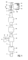
- FIG. 1 shows schematically an embodiment of a device for controlled placing of products in a container according to the invention.
- a device as can be utilized in large warehouses and distribution centres, particularly for stocking retail chains and supermarkets.
- the device comprises a transport path in the form of one or more driven roller conveyors 11 and/or conveyor belts 12 over which products 10 are supplied.
- Products 10 have to be stacked in containers 100 applied standard for this purpose, so-called roller containers, which are provided with a mobile undercarriage 110 having removable racks 120,130 on either side, see figures 5 and 6.
- Such containers typically have a length and width of about 80 cm and are about 180 cm high and are filled in successive layers with the articles for transporting.
- Identification means 20 comprise one or more electronic sensors 21, so-called bar code readers, with which identification labels 22 arranged on product 10 and having thereon an identification code 23 in the form of a pattern of successive bars can be recognized and read.
- the identification means comprise eight such sensors 21, so that an identification label 22 arranged on a product will at all times be read, provided it is visible at all. This latter can be ensured in relatively simple manner by for instance applying two such identification labels 22 on different sides of the product.
- the bar code arranged on the label provides a unique identification of the supplied product, on the basis of which all relevant data concerning the product in question can be retrieved from a central database via an information network (not further shown). This data includes, among other things, the dimensions and the weight of the product, which will be used for subsequent processing.
- the label record provides information relating to the actual orientation of the product.
- Tilting table 40 is coupled to identification means 20 and comprises a stop surface 41 which can be selectively placed in the transport path of the product. Stop surface 41 herein co-acts with a pusher 42 acting on an upper side of product 10 to tilt the product forward on a horizontal axis as it runs up against stop surface 41, assisted herein by the product's own momentum. This momentum is directly proportional to the mass of the product, so that the effort which has to be produced by tilting means 41,42 can also remain relatively small in the case of relatively heavy products, all the more so since the product does not have to be picked up from the transport path.
- the tilting by tilting means 40 is carried out selectively in accordance with the recorded orientation of the product and the eventually desired orientation in container 100.
- a second manipulating station 50 comprising aligning means which are further shown in figure 4.
- the aligning means comprise two controllable actuators 51 which act on product 10 from the side to align it along a central axis of transport path 11.
- the actuators comprise two hydraulic or pneumatic cylinders 51 which are driven on the basis of product information generated by identification means 20.
- the displacement of the piston rod of the pressure cylinders and the force with which the product is acted upon are thus geared precisely to the nature, the size and the weight of the product in question, so that optimal operation is achieved.
- Bearing-mounted rollers 53 on the side of the contact members 53 of the aligning means directed toward product 10 reduce the friction with the product and thus ensure undisturbed transit.
- the product 10 placed centrally in the transport path is transported further to a loading station 60, which has a further manipulator 61 available in the form of a gripper with which the product can be picked up from the transport path and, if desired, can be rotated about a vertical central axis, as shown in further detail in figure 6.
- Gripper 61 runs in a rail system 62 and can be driven herein both in the direction of the transport path and in a direction transversely thereof, so that product 10 can be ideally positioned on a horizontally displaceable platform 65 of the loading means with which the product can be carried into container 100.
- An inner side of the gripper is covered with a layer of friction material 63 in order to always have an effective grip on product 10.
- the platform is driven by two actuators which can be driven independently of each other to enable a linear movement to be performed in a direction transversely of a connecting line with the container as well as in the direction of this line. These actuators are driven on the basis of parameters derived from determined product data of the supplied product. In accordance with the invention this latter operation is kept as simple as possible and, with a view hereto, the product is placed on platform 65 in the most ideal orientation and position using gripper 61. Because the platform lies situated a little below the level of transport path 11,12, the product does not have to be lifted up for this purpose.
- the device is hereby not subject to a load resulting from a product's own weight, or hardly so, and is therefore suitable for handling products of widely varying mass and density.
- the platform After having first been aligned in width direction using platform 65, a single linear movement will now suffice to carry the product on the platform to the desired depth in the container. Both the width alignment and this forward motion are centrally controlled on the basis of the recorded product data and the final position of the product in container 100 predetermined on the basis thereof.
- the platform is provided with discharging means in the form of a linear actuator 66 to push the product therefrom into the desired final position and to cause it to land in the container.
- An optimum filling of the container can thus be precalculated and realized in fully automatic manner using the device.
- the platform can be equipped on a front side with one or more pressure-sensitive, ultrasonic or optical sensors so as to ensure that the platform does not enter the container any further than a free space therein allows. As soon as the platform runs up unexpectedly against a previously loaded product or a rear wall of the container, the sensor will generate a signal on the basis of which the actuator of the platform is for instance switched off in order to avoid breakage or malfunction.
- the container 100 is situated on a loading seat 70 which is height-adjustable by means of a hydraulic cylinder 71 provided for this purpose.
- a hydraulic cylinder 71 provided for this purpose.
- the loading seat 70 By causing the loading seat 70 with container 100 thereon to descend in stepwise manner during the process, container 100 can be filled with products in layers without a further adjustment of loading means 60-65 being required for this purpose.
- the loading seat 70 furthermore provides a slight tilting on a horizontal axis, as indicated in the figure, so that the loaded products lean back somewhat and support against a rear wall of container 100 and seat 70.
- the seat After the seat is thus completely filled, it can optionally be removed in rolling manner at a level lying below the device in order to make room for a subsequent container.
- container 100 is provided, after being filled, with a special front partition 130 having on an inner side thereof an inflatable body 140 which is filled with compressed air in order to fill, wholly or at least for the greater part, the empty space, see figure 5.
- a cover there which in similar manner is provided on an inner side with an inflatable body which is expanded to fill the greater part of the empty space.
- the thus optimally filled containers 100 are placed together in a transport area.
- the transport area is for instance a semi-trailer of a truck or a carriage of a train and comprises, see figure 7, a mobile undercarriage 200 provided with a number of upright walls 210 and a roof plate 220 which enclose a loading space 230.
- a mobile undercarriage 200 provided with a number of upright walls 210 and a roof plate 220 which enclose a loading space 230.
- roof plate 220 there is arranged on roof plate 220 a pattern of inflatable bodies 240 which extend into the loading space,
- the position of these bodies 240 corresponds with the intended position of containers 100 in loading space 230 and the dimensions of the bodies are also adjusted to containers 100 so that, in the expanded state as shown, the bodies 240 enter the containers from the top in order to at least partially fill and cover them. It is thus possible to avoid products 10 moving during transport from one container into another or into the loading space.
- the loading means and manipulators were controlled on the basis of a product identity determined and generated by the identification means.
- the identification means can instead be utilized solely for the purpose of monitoring an otherwise known flow of products, wherein the manipulators and loading means are controlled on the basis of the products expected in the thus presented known sequence.
- the invention provides a device with which products which are widely diverse in weight and size are placed in controlled manner in a container in a reliable and efficient way, in order to thus achieve an optimum degree of filling using limited manpower.
Landscapes
- Engineering & Computer Science (AREA)
- Mechanical Engineering (AREA)
- Transportation (AREA)
- Chemical & Material Sciences (AREA)
- Combustion & Propulsion (AREA)
- Auxiliary Devices For And Details Of Packaging Control (AREA)
- Specific Conveyance Elements (AREA)
- Container Filling Or Packaging Operations (AREA)
- Supplying Of Containers To The Packaging Station (AREA)
- Vending Machines For Individual Products (AREA)
Priority Applications (3)
| Application Number | Priority Date | Filing Date | Title |
|---|---|---|---|
| DE60219020T DE60219020D1 (de) | 2002-10-10 | 2002-10-10 | Vorrichtung zum kontrollierten Einlegen von Erzeugnissen in einen Behälter |
| EP02079207A EP1407992B8 (fr) | 2002-10-10 | 2002-10-10 | Dispositif de mise en place contrôlée de produits dans un récipient |
| AT02079207T ATE357391T1 (de) | 2002-10-10 | 2002-10-10 | Vorrichtung zum kontrollierten einlegen von erzeugnissen in einen behälter |
Applications Claiming Priority (1)
| Application Number | Priority Date | Filing Date | Title |
|---|---|---|---|
| EP02079207A EP1407992B8 (fr) | 2002-10-10 | 2002-10-10 | Dispositif de mise en place contrôlée de produits dans un récipient |
Publications (3)
| Publication Number | Publication Date |
|---|---|
| EP1407992A1 true EP1407992A1 (fr) | 2004-04-14 |
| EP1407992B1 EP1407992B1 (fr) | 2007-03-21 |
| EP1407992B8 EP1407992B8 (fr) | 2007-08-01 |
Family
ID=32011022
Family Applications (1)
| Application Number | Title | Priority Date | Filing Date |
|---|---|---|---|
| EP02079207A Expired - Lifetime EP1407992B8 (fr) | 2002-10-10 | 2002-10-10 | Dispositif de mise en place contrôlée de produits dans un récipient |
Country Status (3)
| Country | Link |
|---|---|
| EP (1) | EP1407992B8 (fr) |
| AT (1) | ATE357391T1 (fr) |
| DE (1) | DE60219020D1 (fr) |
Cited By (5)
| Publication number | Priority date | Publication date | Assignee | Title |
|---|---|---|---|---|
| WO2007031085A1 (fr) * | 2005-09-13 | 2007-03-22 | Fki Logistex A/S | Système et procédé de manipulation automatisée de bagages |
| ES2310445A1 (es) * | 2006-04-21 | 2009-01-01 | Eduardo Alvarez Rodriguez | Cabezal paletizador/despaletizador de accionamiento robotizado. |
| WO2012019591A3 (fr) * | 2010-08-12 | 2012-04-26 | Grenzebach Maschinenbau Gmbh | Dispositif et procédé d'individualisation et de regroupement automatiques d'unités d'emballage de marchandises à expédier, ayant des structures différentes |
| US9150119B2 (en) | 2013-03-15 | 2015-10-06 | Aesynt Incorporated | Apparatuses, systems, and methods for anticipating and delivering medications from a central pharmacy to a patient using a track based transport system |
| US9511945B2 (en) | 2012-10-12 | 2016-12-06 | Aesynt Incorporated | Apparatuses, systems, and methods for transporting medications from a central pharmacy to a patient in a healthcare facility |
Citations (8)
| Publication number | Priority date | Publication date | Assignee | Title |
|---|---|---|---|---|
| GB2094258A (en) * | 1981-03-11 | 1982-09-15 | Prakken Bouwe | Apparatus for introducing filled bags into a box |
| US4608808A (en) * | 1984-06-22 | 1986-09-02 | Frito-Lay, Inc. | Apparatus and method for case packing flexible bags |
| US4720958A (en) * | 1987-02-26 | 1988-01-26 | Rca Corporation | Object aligning and packing system |
| EP0636557A1 (fr) * | 1993-06-30 | 1995-02-01 | Kao Corporation | Procédé et l'appareil pour l'introduction de marchandises aux récipients |
| US5501571A (en) * | 1993-01-21 | 1996-03-26 | International Business Machines Corporation | Automated palletizing system |
| US5944479A (en) * | 1996-10-17 | 1999-08-31 | Ohkuma Corporation | Stacking apparatus |
| EP1035018A1 (fr) * | 1999-03-11 | 2000-09-13 | Studio C.A.D. S.n.c. di Taglioli V. & C. | Machine pour emballer des objets dans des récipients obtenus à partir de flans tubulaires plats et pliés , et pour fermer des récipients remplis |
| US6257825B1 (en) * | 1999-06-22 | 2001-07-10 | Sage Automation, Inc. | Robotic palletizing system |
-
2002
- 2002-10-10 AT AT02079207T patent/ATE357391T1/de not_active IP Right Cessation
- 2002-10-10 EP EP02079207A patent/EP1407992B8/fr not_active Expired - Lifetime
- 2002-10-10 DE DE60219020T patent/DE60219020D1/de not_active Expired - Lifetime
Patent Citations (8)
| Publication number | Priority date | Publication date | Assignee | Title |
|---|---|---|---|---|
| GB2094258A (en) * | 1981-03-11 | 1982-09-15 | Prakken Bouwe | Apparatus for introducing filled bags into a box |
| US4608808A (en) * | 1984-06-22 | 1986-09-02 | Frito-Lay, Inc. | Apparatus and method for case packing flexible bags |
| US4720958A (en) * | 1987-02-26 | 1988-01-26 | Rca Corporation | Object aligning and packing system |
| US5501571A (en) * | 1993-01-21 | 1996-03-26 | International Business Machines Corporation | Automated palletizing system |
| EP0636557A1 (fr) * | 1993-06-30 | 1995-02-01 | Kao Corporation | Procédé et l'appareil pour l'introduction de marchandises aux récipients |
| US5944479A (en) * | 1996-10-17 | 1999-08-31 | Ohkuma Corporation | Stacking apparatus |
| EP1035018A1 (fr) * | 1999-03-11 | 2000-09-13 | Studio C.A.D. S.n.c. di Taglioli V. & C. | Machine pour emballer des objets dans des récipients obtenus à partir de flans tubulaires plats et pliés , et pour fermer des récipients remplis |
| US6257825B1 (en) * | 1999-06-22 | 2001-07-10 | Sage Automation, Inc. | Robotic palletizing system |
Cited By (13)
| Publication number | Priority date | Publication date | Assignee | Title |
|---|---|---|---|---|
| WO2007031085A1 (fr) * | 2005-09-13 | 2007-03-22 | Fki Logistex A/S | Système et procédé de manipulation automatisée de bagages |
| US7753191B2 (en) | 2005-09-13 | 2010-07-13 | Crisplant A/S | System and method for automated handling of baggage objects |
| EP1931584B1 (fr) | 2005-09-13 | 2017-07-19 | Beumer Group A/S | Système et procédé de manipulation automatisée de bagages |
| ES2310445A1 (es) * | 2006-04-21 | 2009-01-01 | Eduardo Alvarez Rodriguez | Cabezal paletizador/despaletizador de accionamiento robotizado. |
| ES2310445B1 (es) * | 2006-04-21 | 2009-11-10 | Eduardo Alvarez Rodriguez | Cabezal paletizador/despaletizador de accionamiento robotizado. |
| WO2012019591A3 (fr) * | 2010-08-12 | 2012-04-26 | Grenzebach Maschinenbau Gmbh | Dispositif et procédé d'individualisation et de regroupement automatiques d'unités d'emballage de marchandises à expédier, ayant des structures différentes |
| US9511945B2 (en) | 2012-10-12 | 2016-12-06 | Aesynt Incorporated | Apparatuses, systems, and methods for transporting medications from a central pharmacy to a patient in a healthcare facility |
| US10029856B2 (en) | 2012-10-12 | 2018-07-24 | Aesynt Incorporated | Apparatuses, systems, and methods for transporting medications from a central pharmacy to a patient in a healthcare facility |
| US10315851B2 (en) | 2012-10-12 | 2019-06-11 | Aesynt Incorporated | Apparatuses, systems, and methods for transporting medications from a central pharmacy to a patient in a healthcare facility |
| US10518981B2 (en) | 2012-10-12 | 2019-12-31 | Aesynt Incorporated | Apparatuses, systems, and methods for transporting medications from a central pharmacy to a patient in a healthcare facility |
| US10850926B2 (en) | 2012-10-12 | 2020-12-01 | Omnicell, Inc. | Apparatuses, systems, and methods for transporting medications from a central pharmacy to a patient in a healthcare facility |
| US11694782B2 (en) | 2012-10-12 | 2023-07-04 | Omnicell, Inc. | Apparatuses, systems, and methods for transporting medications from a central pharmacy to a patient in a healthcare facility |
| US9150119B2 (en) | 2013-03-15 | 2015-10-06 | Aesynt Incorporated | Apparatuses, systems, and methods for anticipating and delivering medications from a central pharmacy to a patient using a track based transport system |
Also Published As
| Publication number | Publication date |
|---|---|
| DE60219020D1 (de) | 2007-05-03 |
| EP1407992B8 (fr) | 2007-08-01 |
| EP1407992B1 (fr) | 2007-03-21 |
| ATE357391T1 (de) | 2007-04-15 |
Similar Documents
| Publication | Publication Date | Title |
|---|---|---|
| US20080019819A1 (en) | Palletizer apparatus and method | |
| US7735625B2 (en) | Apparatus and method for unloading trays having a pallet layer loaded | |
| US9764909B2 (en) | Device and method for quickly grouping picked goods for transport | |
| US20080014074A1 (en) | Off-the-bottom Depalletizer apparatus and method | |
| KR102728704B1 (ko) | 케이스 재배향 시스템 및 방법 | |
| WO2019204450A1 (fr) | Outil d'extrémité de bras (eoat) pour cartons de boisson | |
| CN212768195U (zh) | 货物托盘分离处理设备和自动装车设备 | |
| US20230348192A1 (en) | Method and order-picking storage facility for storing and order-picking goods | |
| FI3497043T3 (fi) | Lastausjärjestelmä sekalaisten tuotteiden kuormaamiseksi kohdekuormalavalle | |
| US11180327B2 (en) | Method for automatically stacking packages in layers on a support | |
| CA2814666A1 (fr) | Appareil et procede pour charger et decharger des conteneurs | |
| US10759059B2 (en) | Automated bin packing tool method | |
| AU2023220639A1 (en) | Method and device for automatically stacking packages on a support in multiple layers | |
| EP1407992B1 (fr) | Dispositif de mise en place contrôlée de produits dans un récipient | |
| EP1740487B1 (fr) | Gerbeur et procede | |
| US12187553B2 (en) | Intelligent robotized depalletizer | |
| CA3257773A1 (fr) | Appareil et procédé de réalisation d'unités de charge combinées | |
| NL1017948C2 (nl) | Inrichting voor het gecontroleerd in een houder plaatsen van producten alsmede een houder en een transportruimte. | |
| JP4029688B2 (ja) | 自動倉庫設備 | |
| NL8004438A (nl) | Inrichting voor het in gedeelten verplaatsen van een stapel kratten, bakken of dozen. | |
| US9090411B2 (en) | Apparatus and method for loading and unloading containers | |
| JP4090319B2 (ja) | 荷姿変換方法および荷姿変換設備 | |
| JP4151364B2 (ja) | ケース体保管方法およびケース体保管設備 | |
| JP4122888B2 (ja) | 物品搬送設備を備えた自動倉庫設備 | |
| EP1967468A1 (fr) | Chariot doté d'un convoyeur pour récipients |
Legal Events
| Date | Code | Title | Description |
|---|---|---|---|
| PUAI | Public reference made under article 153(3) epc to a published international application that has entered the european phase |
Free format text: ORIGINAL CODE: 0009012 |
|
| AK | Designated contracting states |
Kind code of ref document: A1 Designated state(s): AT BE BG CH CY CZ DE DK EE ES FI FR GB GR IE IT LI LU MC NL PT SE SK TR |
|
| AX | Request for extension of the european patent |
Extension state: AL LT LV MK RO SI |
|
| 17P | Request for examination filed |
Effective date: 20041014 |
|
| AKX | Designation fees paid |
Designated state(s): AT BE BG CH CY CZ DE DK EE ES FI FR GB GR IE IT LI LU MC NL PT SE SK TR |
|
| 17Q | First examination report despatched |
Effective date: 20050309 |
|
| GRAC | Information related to communication of intention to grant a patent modified |
Free format text: ORIGINAL CODE: EPIDOSCIGR1 |
|
| GRAP | Despatch of communication of intention to grant a patent |
Free format text: ORIGINAL CODE: EPIDOSNIGR1 |
|
| RTI1 | Title (correction) |
Free format text: DEVICE FOR THE CONTROLLED PLACING OF PRODUCTS INTO A CONTAINER |
|
| GRAS | Grant fee paid |
Free format text: ORIGINAL CODE: EPIDOSNIGR3 |
|
| R17C | First examination report despatched (corrected) |
Effective date: 20050309 |
|
| GRAA | (expected) grant |
Free format text: ORIGINAL CODE: 0009210 |
|
| AK | Designated contracting states |
Kind code of ref document: B1 Designated state(s): AT BE BG CH CY CZ DE DK EE ES FI FR GB GR IE IT LI LU MC NL PT SE SK TR |
|
| PG25 | Lapsed in a contracting state [announced via postgrant information from national office to epo] |
Ref country code: CH Free format text: LAPSE BECAUSE OF FAILURE TO SUBMIT A TRANSLATION OF THE DESCRIPTION OR TO PAY THE FEE WITHIN THE PRESCRIBED TIME-LIMIT Effective date: 20070321 Ref country code: BE Free format text: LAPSE BECAUSE OF FAILURE TO SUBMIT A TRANSLATION OF THE DESCRIPTION OR TO PAY THE FEE WITHIN THE PRESCRIBED TIME-LIMIT Effective date: 20070321 Ref country code: LI Free format text: LAPSE BECAUSE OF FAILURE TO SUBMIT A TRANSLATION OF THE DESCRIPTION OR TO PAY THE FEE WITHIN THE PRESCRIBED TIME-LIMIT Effective date: 20070321 Ref country code: FI Free format text: LAPSE BECAUSE OF FAILURE TO SUBMIT A TRANSLATION OF THE DESCRIPTION OR TO PAY THE FEE WITHIN THE PRESCRIBED TIME-LIMIT Effective date: 20070321 Ref country code: AT Free format text: LAPSE BECAUSE OF FAILURE TO SUBMIT A TRANSLATION OF THE DESCRIPTION OR TO PAY THE FEE WITHIN THE PRESCRIBED TIME-LIMIT Effective date: 20070321 |
|
| REG | Reference to a national code |
Ref country code: GB Ref legal event code: FG4D |
|
| REG | Reference to a national code |
Ref country code: CH Ref legal event code: EP |
|
| RAP2 | Party data changed (patent owner data changed or rights of a patent transferred) |
Owner name: IDS B.V. |
|
| REF | Corresponds to: |
Ref document number: 60219020 Country of ref document: DE Date of ref document: 20070503 Kind code of ref document: P |
|
| REG | Reference to a national code |
Ref country code: IE Ref legal event code: FG4D |
|
| PG25 | Lapsed in a contracting state [announced via postgrant information from national office to epo] |
Ref country code: SE Free format text: LAPSE BECAUSE OF FAILURE TO SUBMIT A TRANSLATION OF THE DESCRIPTION OR TO PAY THE FEE WITHIN THE PRESCRIBED TIME-LIMIT Effective date: 20070621 |
|
| NLT2 | Nl: modifications (of names), taken from the european patent patent bulletin |
Owner name: IDS B.V. Effective date: 20070502 |
|
| PG25 | Lapsed in a contracting state [announced via postgrant information from national office to epo] |
Ref country code: ES Free format text: LAPSE BECAUSE OF FAILURE TO SUBMIT A TRANSLATION OF THE DESCRIPTION OR TO PAY THE FEE WITHIN THE PRESCRIBED TIME-LIMIT Effective date: 20070702 |
|
| PG25 | Lapsed in a contracting state [announced via postgrant information from national office to epo] |
Ref country code: PT Free format text: LAPSE BECAUSE OF FAILURE TO SUBMIT A TRANSLATION OF THE DESCRIPTION OR TO PAY THE FEE WITHIN THE PRESCRIBED TIME-LIMIT Effective date: 20070821 |
|
| REG | Reference to a national code |
Ref country code: CH Ref legal event code: PL |
|
| EN | Fr: translation not filed | ||
| PG25 | Lapsed in a contracting state [announced via postgrant information from national office to epo] |
Ref country code: SK Free format text: LAPSE BECAUSE OF FAILURE TO SUBMIT A TRANSLATION OF THE DESCRIPTION OR TO PAY THE FEE WITHIN THE PRESCRIBED TIME-LIMIT Effective date: 20070321 |
|
| PG25 | Lapsed in a contracting state [announced via postgrant information from national office to epo] |
Ref country code: CZ Free format text: LAPSE BECAUSE OF FAILURE TO SUBMIT A TRANSLATION OF THE DESCRIPTION OR TO PAY THE FEE WITHIN THE PRESCRIBED TIME-LIMIT Effective date: 20070321 |
|
| PLBE | No opposition filed within time limit |
Free format text: ORIGINAL CODE: 0009261 |
|
| STAA | Information on the status of an ep patent application or granted ep patent |
Free format text: STATUS: NO OPPOSITION FILED WITHIN TIME LIMIT |
|
| PG25 | Lapsed in a contracting state [announced via postgrant information from national office to epo] |
Ref country code: DK Free format text: LAPSE BECAUSE OF FAILURE TO SUBMIT A TRANSLATION OF THE DESCRIPTION OR TO PAY THE FEE WITHIN THE PRESCRIBED TIME-LIMIT Effective date: 20070321 Ref country code: DE Free format text: LAPSE BECAUSE OF FAILURE TO SUBMIT A TRANSLATION OF THE DESCRIPTION OR TO PAY THE FEE WITHIN THE PRESCRIBED TIME-LIMIT Effective date: 20070622 |
|
| PGFP | Annual fee paid to national office [announced via postgrant information from national office to epo] |
Ref country code: NL Payment date: 20071031 Year of fee payment: 6 |
|
| 26N | No opposition filed |
Effective date: 20071227 |
|
| PG25 | Lapsed in a contracting state [announced via postgrant information from national office to epo] |
Ref country code: FR Free format text: LAPSE BECAUSE OF FAILURE TO SUBMIT A TRANSLATION OF THE DESCRIPTION OR TO PAY THE FEE WITHIN THE PRESCRIBED TIME-LIMIT Effective date: 20071123 Ref country code: GR Free format text: LAPSE BECAUSE OF FAILURE TO SUBMIT A TRANSLATION OF THE DESCRIPTION OR TO PAY THE FEE WITHIN THE PRESCRIBED TIME-LIMIT Effective date: 20070622 Ref country code: IT Free format text: LAPSE BECAUSE OF FAILURE TO SUBMIT A TRANSLATION OF THE DESCRIPTION OR TO PAY THE FEE WITHIN THE PRESCRIBED TIME-LIMIT Effective date: 20070321 |
|
| PG25 | Lapsed in a contracting state [announced via postgrant information from national office to epo] |
Ref country code: MC Free format text: LAPSE BECAUSE OF NON-PAYMENT OF DUE FEES Effective date: 20071031 |
|
| GBPC | Gb: european patent ceased through non-payment of renewal fee |
Effective date: 20071010 |
|
| PG25 | Lapsed in a contracting state [announced via postgrant information from national office to epo] |
Ref country code: IE Free format text: LAPSE BECAUSE OF NON-PAYMENT OF DUE FEES Effective date: 20071010 |
|
| PG25 | Lapsed in a contracting state [announced via postgrant information from national office to epo] |
Ref country code: GB Free format text: LAPSE BECAUSE OF NON-PAYMENT OF DUE FEES Effective date: 20071010 Ref country code: FR Free format text: LAPSE BECAUSE OF FAILURE TO SUBMIT A TRANSLATION OF THE DESCRIPTION OR TO PAY THE FEE WITHIN THE PRESCRIBED TIME-LIMIT Effective date: 20070321 |
|
| PG25 | Lapsed in a contracting state [announced via postgrant information from national office to epo] |
Ref country code: EE Free format text: LAPSE BECAUSE OF FAILURE TO SUBMIT A TRANSLATION OF THE DESCRIPTION OR TO PAY THE FEE WITHIN THE PRESCRIBED TIME-LIMIT Effective date: 20070321 |
|
| NLV4 | Nl: lapsed or anulled due to non-payment of the annual fee |
Effective date: 20090501 |
|
| PG25 | Lapsed in a contracting state [announced via postgrant information from national office to epo] |
Ref country code: CY Free format text: LAPSE BECAUSE OF FAILURE TO SUBMIT A TRANSLATION OF THE DESCRIPTION OR TO PAY THE FEE WITHIN THE PRESCRIBED TIME-LIMIT Effective date: 20070321 Ref country code: NL Free format text: LAPSE BECAUSE OF NON-PAYMENT OF DUE FEES Effective date: 20090501 |
|
| PG25 | Lapsed in a contracting state [announced via postgrant information from national office to epo] |
Ref country code: LU Free format text: LAPSE BECAUSE OF NON-PAYMENT OF DUE FEES Effective date: 20071010 Ref country code: BG Free format text: LAPSE BECAUSE OF FAILURE TO SUBMIT A TRANSLATION OF THE DESCRIPTION OR TO PAY THE FEE WITHIN THE PRESCRIBED TIME-LIMIT Effective date: 20070621 |
|
| PG25 | Lapsed in a contracting state [announced via postgrant information from national office to epo] |
Ref country code: TR Free format text: LAPSE BECAUSE OF FAILURE TO SUBMIT A TRANSLATION OF THE DESCRIPTION OR TO PAY THE FEE WITHIN THE PRESCRIBED TIME-LIMIT Effective date: 20070321 |