EP1408136A1 - Cible cylindrique pour évaporation à arc, son procédé de fabrication et dispositif de dépot la comprenant - Google Patents
Cible cylindrique pour évaporation à arc, son procédé de fabrication et dispositif de dépot la comprenant Download PDFInfo
- Publication number
- EP1408136A1 EP1408136A1 EP03021245A EP03021245A EP1408136A1 EP 1408136 A1 EP1408136 A1 EP 1408136A1 EP 03021245 A EP03021245 A EP 03021245A EP 03021245 A EP03021245 A EP 03021245A EP 1408136 A1 EP1408136 A1 EP 1408136A1
- Authority
- EP
- European Patent Office
- Prior art keywords
- rod target
- target
- rod
- evaporation source
- longitudinal direction
- Prior art date
- Legal status (The legal status is an assumption and is not a legal conclusion. Google has not performed a legal analysis and makes no representation as to the accuracy of the status listed.)
- Granted
Links
- 238000001704 evaporation Methods 0.000 title claims abstract description 39
- 230000008020 evaporation Effects 0.000 title claims abstract description 38
- 230000008021 deposition Effects 0.000 title claims description 6
- 238000004519 manufacturing process Methods 0.000 title claims description 5
- 230000002093 peripheral effect Effects 0.000 claims abstract description 9
- 239000013077 target material Substances 0.000 claims description 11
- 230000007423 decrease Effects 0.000 claims description 8
- 238000000034 method Methods 0.000 claims description 3
- 239000002699 waste material Substances 0.000 abstract description 7
- 230000000694 effects Effects 0.000 description 7
- 238000012360 testing method Methods 0.000 description 6
- 239000011248 coating agent Substances 0.000 description 5
- 238000000576 coating method Methods 0.000 description 5
- 238000009826 distribution Methods 0.000 description 5
- 238000012545 processing Methods 0.000 description 5
- IJGRMHOSHXDMSA-UHFFFAOYSA-N Atomic nitrogen Chemical compound N#N IJGRMHOSHXDMSA-UHFFFAOYSA-N 0.000 description 4
- 238000000151 deposition Methods 0.000 description 4
- 238000001513 hot isostatic pressing Methods 0.000 description 4
- 239000007787 solid Substances 0.000 description 4
- 238000005336 cracking Methods 0.000 description 3
- 230000008646 thermal stress Effects 0.000 description 3
- 238000010586 diagram Methods 0.000 description 2
- 238000010891 electric arc Methods 0.000 description 2
- 229910052757 nitrogen Inorganic materials 0.000 description 2
- 238000012546 transfer Methods 0.000 description 2
- 238000001771 vacuum deposition Methods 0.000 description 2
- 230000001174 ascending effect Effects 0.000 description 1
- 230000015572 biosynthetic process Effects 0.000 description 1
- 239000002775 capsule Substances 0.000 description 1
- 150000001875 compounds Chemical class 0.000 description 1
- 239000012141 concentrate Substances 0.000 description 1
- 238000005520 cutting process Methods 0.000 description 1
- 238000013461 design Methods 0.000 description 1
- 239000007789 gas Substances 0.000 description 1
- 230000014509 gene expression Effects 0.000 description 1
- 150000002500 ions Chemical class 0.000 description 1
- 239000000463 material Substances 0.000 description 1
- 238000000465 moulding Methods 0.000 description 1
- 239000000843 powder Substances 0.000 description 1
- 238000004544 sputter deposition Methods 0.000 description 1
Images


Classifications
-
- C—CHEMISTRY; METALLURGY
- C23—COATING METALLIC MATERIAL; COATING MATERIAL WITH METALLIC MATERIAL; CHEMICAL SURFACE TREATMENT; DIFFUSION TREATMENT OF METALLIC MATERIAL; COATING BY VACUUM EVAPORATION, BY SPUTTERING, BY ION IMPLANTATION OR BY CHEMICAL VAPOUR DEPOSITION, IN GENERAL; INHIBITING CORROSION OF METALLIC MATERIAL OR INCRUSTATION IN GENERAL
- C23C—COATING METALLIC MATERIAL; COATING MATERIAL WITH METALLIC MATERIAL; SURFACE TREATMENT OF METALLIC MATERIAL BY DIFFUSION INTO THE SURFACE, BY CHEMICAL CONVERSION OR SUBSTITUTION; COATING BY VACUUM EVAPORATION, BY SPUTTERING, BY ION IMPLANTATION OR BY CHEMICAL VAPOUR DEPOSITION, IN GENERAL
- C23C14/00—Coating by vacuum evaporation, by sputtering or by ion implantation of the coating forming material
- C23C14/22—Coating by vacuum evaporation, by sputtering or by ion implantation of the coating forming material characterised by the process of coating
- C23C14/24—Vacuum evaporation
- C23C14/32—Vacuum evaporation by explosion; by evaporation and subsequent ionisation of the vapours, e.g. ion-plating
- C23C14/325—Electric arc evaporation
Definitions
- the present invention relates to a rod target for an arc evaporation source used for anti-wear coating treatment with respect to cutting tools, mechanical components and the like, a manufacturing method therefor, and an arc deposition device.
- an example of a conventional vacuum arc deposition device is such that a rod target 52 for an arc evaporation source, and work 53 are provided in a vacuum vessel 51; the cathode of an arc power supply 54 is connected to the rod target 52 to input a current to the rod target 52; a target material is evaporated from the outer peripheral surface of the rod target 52 by changing the current balance; and the evaporated target material is caused to adhere to the work 53 (for example, see Japanese Unexamined Patent Application Publication No. 07-173617).
- the object of the present invention is to provide work with a uniform film thickness, and improve the availability of the rod target, thereby preventing the rod target from going to waste.
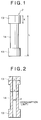
- the present invention provides a rod target for an arc evaporation source, the rod target employing its outer peripheral surface as an evaporation surface, wherein the opposite ends thereof in the longitudinal direction thereof are each formed thicker than the central part thereof.
- the length of the thicker portion at each of the opposite ends of the rod target in the longitudinal direction thereof is preferably set to be not less than 75 mm nor more than 200 mm.
- the length of the thicker portion affects the uniformity of film thickness and the availability of the rod target, irrespective of the entire length of the rod target.
- the ratio of the effective consumed sectional area of the thicker portion at each of the opposite ends of the rod target in the longitudinal direction thereof with respect to the effective consumed sectional area of the narrower portion in the central part thereof is preferably set to be more than 1.0 and not more than 3.0.
- the boundary portion between the thicker portion at each of the opposite ends of the rod target in the longitudinal direction thereof and the narrower portion in the central part thereof may be changed in the thickness in a step-by-step manner so that the thickness thereof gradually decreases from the thicker portion at each of the opposite ends thereof in the longitudinal direction thereof toward the narrower portion in the central part thereof.
- a taper portion may be provided in the boundary portion between the thicker portion at each of the opposite ends of the rod target in the longitudinal direction thereof and the narrower portion in the central part thereof so that the diameter thereof gradually decreases from each of the thicker portions toward the narrower portion.
- the present invention provides a method for manufacturing the rod target for an arc evaporation source as mentioned above, comprising integrally assembling the thicker portion at each of the opposite ends thereof in the longitudinal direction thereof and the narrower portion in the central part thereof, after, at least, separately producing the thicker portion at each of the opposite ends thereof in the longitudinal direction thereof and the narrower portion in the central part thereof.
- the present invention provides an arc deposition device in which a rod target for an arc evaporation source and work are provided in a vacuum vessel, in which a target material is evaporated from the outer peripheral surface of the rod target for an arc evaporation source, and in which the evaporated target material is caused to be adhered to the work.
- the rod target for an arc evaporation source as mentioned above is used as the rod target for an arc evaporation source provided in the vacuum vessel.
- the work is provided with a uniform film thickness, and the availability of the rod target is improved, whereby waste of the target material is eliminated, resulting in an economic advantage.
- a hollow cylindrical rod target 2 for an arc evaporation source and work 3 are provided in a vacuum vessel 1 for a vacuum deposition device.
- the rod target 2 is disposed in the central part of the vacuum vessel 1 along the up-and-down direction.
- a rotational table 5 is provided in a lower portion of the vacuum vessel 1.
- the rotational table 5 is supported so as to be rotatable about its vertical axis substantially coaxial with the rod target 2.
- the work 3 is placed on the rotational table 5 through the intermediary of a holding member 6.
- the work 3 is configured to revolute about the rod target 2 with the rotation of the rotational table 5 and simultaneously to rotate together with the holding member 6 about the vertical axis thereof.
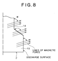
- a magnet 8 is provided in the rod target 2 so as to be movable up and down.
- the cathode of an arc power supply 10 is connected to the top end of the rod target 2.
- the anode of the arc power supply 10 is connected to the vacuum vessel 1.
- the vacuum vessel 1 is first evacuated by a vacuum pump (not shown) to keep the inside of the vacuum vessel in a vacuum state with a predetermined pressure.
- a vacuum arc discharge is generated from the rod target 2 by an ignition unit (not shown)
- an arc spot in which an arc current is concentrated appears on the surface (outer peripheral surface) of the rod target 2.
- a target material is evaporated from the outer peripheral surface of the rod target 2 while controlling the position of the arc spot by ascending/descending of the magnet 8.
- the vapor of the evaporated target material moves toward the work 3 disposed in the vacuum vessel 1, and forms a coating on the work 3.
- a negative voltage bias voltage
- a power supply not shown
- coating formation is performed while accelerating ions in the vapor.
- a reactive gas such as nitrogen may be introduced into the vacuum vessel 1 to form a coating comprising a compound of the target material and nitrogen.
- the opposite ends thereof in the longitudinal direction thereof are formed thicker than the central part thereof. Namely, a thicker portion (larger diameter portion) 13 is provided at each of the opposite ends of the rod target 2 in the longitudinal direction thereof, and a narrower portion (smaller diameter portion) 14 is provided in the central part thereof.
- the length x of the thicker portion 13 at each of the opposite ends of the target rod 2 in the longitudinal direction thereof is set to be not less than 75 mm nor more than 200 mm, and is preferably set to 100 to 150 mm.
- the ratio of the effective consumed sectional area of the thicker portion at each of the opposite ends of the target rod 2 in the longitudinal direction thereof with respect to the effective consumed sectional area of the narrower portion in the central part thereof is set to be more than 1.0 and not more than 3.0, and is preferably set to 1.5 to 2.5.
- the manufacturing method for the rod target 2 shown in Fig. 9 can be applied not only to the rod target 2 according to the embodiments shown in Figs. 1 and 2, but also to the rod target 2 according to the embodiments shown in Figs. 4 to 6.
- the boundary portion (steps 16 and taper portion 17) between each of the larger diameter portions 13 and the smaller diameter portion 14 may also be separately produced, and thereafter all of these may be integrally coupled.
- Table 1 shows the target consumption amount (volume), and the consumption efficiency (up to the limit consumption), i.e., (the volume consumed or evaporated until the lifetime expires) ⁇ (the initial volume), when the length x of the larger diameter portion 13 of the rod target is varied, using a rod target having the entire length L of 700 mm, the outer diameter z of its smaller diameter portion 14 of 100 mm, and the outer diameter y of its larger diameter portion 13 of 125 mm. Variations in the film thickness distribution was maintained within ⁇ 5%, and the target consumption limit was set to ⁇ 70 mm.
- the consumption efficiency was higher when the length x of the larger diameter portion 13 was 100 to 150 mm, and was the highest when the length x of the larger diameter portion 13 was 125 mm.
- the length x of the larger diameter portion 13 that allows the consumption efficiency to be the maximum somewhat depends upon the distance between the rod target 2 and the work 3, or the like. However, irrespective of the difference in the distance between the rod target 2 and the work 3, substantially the same consumption efficiency tendency was observed, and the consumption efficiency was optimum when the length x of the larger diameter portion 13 is in the neighborhood of 150 mm.
- Table 2 shows the consumption efficiency of the rod target 2 when the outer diameter y of the large diameter portion 13 thereof is varied, with the length of the large diameter portion 13 set to 125 mm.
- the rod target 2 a hollow cylindrical one was used.
- the shape of the rod target 2 is not limited to a hollow cylindrical one.
- a solid cylindrical shape may be used, or alternatively a hollow elliptic cylindrical shape or a solid elliptic cylindrical shape may also be adopted.
- the opposite ends thereof in the longitudinal direction thereof are each formed thicker than the central part thereof.
- the length of the thicker portion at each of the opposite ends in the longitudinal direction is set to be not less than 75 mm nor more than 200 mm. Work with a uniform film thickness is provided, and the availability of a rod target is improved, thereby preventing the rod target from going to waste.
Landscapes
- Chemical & Material Sciences (AREA)
- Chemical Kinetics & Catalysis (AREA)
- Engineering & Computer Science (AREA)
- Materials Engineering (AREA)
- Mechanical Engineering (AREA)
- Metallurgy (AREA)
- Organic Chemistry (AREA)
- Physical Vapour Deposition (AREA)
Applications Claiming Priority (2)
| Application Number | Priority Date | Filing Date | Title |
|---|---|---|---|
| JP2002273880A JP4014982B2 (ja) | 2002-09-19 | 2002-09-19 | アーク蒸発源用のロッドターゲット、その製造方法及びアーク蒸着装置 |
| JP2002273880 | 2002-09-19 |
Publications (2)
| Publication Number | Publication Date |
|---|---|
| EP1408136A1 true EP1408136A1 (fr) | 2004-04-14 |
| EP1408136B1 EP1408136B1 (fr) | 2012-11-14 |
Family
ID=31986937
Family Applications (1)
| Application Number | Title | Priority Date | Filing Date |
|---|---|---|---|
| EP03021245A Revoked EP1408136B1 (fr) | 2002-09-19 | 2003-09-18 | Cible cylindrique pour évaporation à arc, son procédé de fabrication et dispositif de dépot la comprenant |
Country Status (4)
| Country | Link |
|---|---|
| US (1) | US7029560B2 (fr) |
| EP (1) | EP1408136B1 (fr) |
| JP (1) | JP4014982B2 (fr) |
| KR (1) | KR100571900B1 (fr) |
Cited By (1)
| Publication number | Priority date | Publication date | Assignee | Title |
|---|---|---|---|---|
| GB2410255A (en) * | 2004-01-21 | 2005-07-27 | Nanofilm Technologies Int | Arc deposition method and apparatus |
Families Citing this family (10)
| Publication number | Priority date | Publication date | Assignee | Title |
|---|---|---|---|---|
| US6560349B1 (en) * | 1994-10-21 | 2003-05-06 | Digimarc Corporation | Audio monitoring using steganographic information |
| JP4110175B2 (ja) | 2006-03-22 | 2008-07-02 | 株式会社神戸製鋼所 | アークイオンプレーティング方法 |
| JP2008159238A (ja) * | 2006-11-30 | 2008-07-10 | Matsushita Electric Ind Co Ltd | 音声データ送信装置および音声データ受信装置 |
| US8088260B2 (en) * | 2007-08-14 | 2012-01-03 | United Technologies Corporation | Puck for cathodic arc coating with continuous groove to control arc |
| US10304665B2 (en) | 2011-09-07 | 2019-05-28 | Nano-Product Engineering, LLC | Reactors for plasma-assisted processes and associated methods |
| US9761424B1 (en) | 2011-09-07 | 2017-09-12 | Nano-Product Engineering, LLC | Filtered cathodic arc method, apparatus and applications thereof |
| AT12292U3 (de) * | 2011-10-18 | 2013-03-15 | Plansee Se | Rohrtarget |
| KR102371334B1 (ko) * | 2017-12-27 | 2022-03-04 | 캐논 아네르바 가부시키가이샤 | 성막 방법 및 성막 장치 |
| US11834204B1 (en) | 2018-04-05 | 2023-12-05 | Nano-Product Engineering, LLC | Sources for plasma assisted electric propulsion |
| KR102067820B1 (ko) * | 2018-07-24 | 2020-01-17 | (주)선익시스템 | 가변형 아크억제수단이 마련된 증착장비 |
Citations (3)
| Publication number | Priority date | Publication date | Assignee | Title |
|---|---|---|---|---|
| JPS5295581A (en) | 1976-02-09 | 1977-08-11 | Anelva Corp | Sputiering apparatus |
| JPH06220617A (ja) | 1993-01-22 | 1994-08-09 | Kobe Steel Ltd | 物理気相蒸着用コーティング材 |
| EP0658634A1 (fr) * | 1993-12-17 | 1995-06-21 | KABUSHIKI KAISHA KOBE SEIKO SHO also known as Kobe Steel Ltd. | Dispositif de dépôt par arc sous vide |
Family Cites Families (5)
| Publication number | Priority date | Publication date | Assignee | Title |
|---|---|---|---|---|
| US3400070A (en) * | 1965-06-14 | 1968-09-03 | Hercules Inc | High efficiency plasma processing head including a diffuser having an expanding diameter |
| US4505947A (en) * | 1982-07-14 | 1985-03-19 | The Standard Oil Company (Ohio) | Method for the deposition of coatings upon substrates utilizing a high pressure, non-local thermal equilibrium arc plasma |
| JP3199543B2 (ja) | 1993-12-17 | 2001-08-20 | 株式会社神戸製鋼所 | 真空アーク蒸着装置 |
| JP2000080466A (ja) | 1998-09-01 | 2000-03-21 | Kobe Steel Ltd | 真空アーク蒸着装置 |
| JP2001059165A (ja) | 1999-08-18 | 2001-03-06 | Nissin Electric Co Ltd | アーク式イオンプレーティング装置 |
-
2002
- 2002-09-19 JP JP2002273880A patent/JP4014982B2/ja not_active Expired - Lifetime
-
2003
- 2003-09-16 US US10/662,280 patent/US7029560B2/en not_active Expired - Lifetime
- 2003-09-18 EP EP03021245A patent/EP1408136B1/fr not_active Revoked
- 2003-09-18 KR KR1020030064669A patent/KR100571900B1/ko not_active Expired - Lifetime
Patent Citations (3)
| Publication number | Priority date | Publication date | Assignee | Title |
|---|---|---|---|---|
| JPS5295581A (en) | 1976-02-09 | 1977-08-11 | Anelva Corp | Sputiering apparatus |
| JPH06220617A (ja) | 1993-01-22 | 1994-08-09 | Kobe Steel Ltd | 物理気相蒸着用コーティング材 |
| EP0658634A1 (fr) * | 1993-12-17 | 1995-06-21 | KABUSHIKI KAISHA KOBE SEIKO SHO also known as Kobe Steel Ltd. | Dispositif de dépôt par arc sous vide |
Non-Patent Citations (2)
| Title |
|---|
| PATENT ABSTRACTS OF JAPAN vol. 001, no. 149 (C - 031) 30 November 1977 (1977-11-30) * |
| PATENT ABSTRACTS OF JAPAN vol. 018, no. 591 (C - 1272) 11 November 1994 (1994-11-11) * |
Cited By (1)
| Publication number | Priority date | Publication date | Assignee | Title |
|---|---|---|---|---|
| GB2410255A (en) * | 2004-01-21 | 2005-07-27 | Nanofilm Technologies Int | Arc deposition method and apparatus |
Also Published As
| Publication number | Publication date |
|---|---|
| JP2004107750A (ja) | 2004-04-08 |
| EP1408136B1 (fr) | 2012-11-14 |
| US7029560B2 (en) | 2006-04-18 |
| JP4014982B2 (ja) | 2007-11-28 |
| KR100571900B1 (ko) | 2006-04-18 |
| US20040055884A1 (en) | 2004-03-25 |
| KR20040025623A (ko) | 2004-03-24 |
Similar Documents
| Publication | Publication Date | Title |
|---|---|---|
| US7029560B2 (en) | Rod target for arc evaporation source, manufacturing method therefor, and arc deposition device | |
| EP1193733B1 (fr) | Lampe à décharge à arc court | |
| EP1312695B1 (fr) | Cible de pulverisation produisant peu de particules, plaque support avec la cible de pulverisation, et procede de production de la cible de pulverisation | |
| EP1997932A1 (fr) | Procede de placage ionique a l'arc et cible a utiliser dans ce cadre | |
| EP1813693B1 (fr) | Ensemble plaque de renfort pour cible de pulvérisation cathodique et système de déposition de film | |
| JPS5944387B2 (ja) | 磁気的に増大させたスパツタ源 | |
| KR20160150641A (ko) | 아크 증발원의 변형 가능한 자석 배치 | |
| EP0890972B1 (fr) | Cathode imprégnée et procédé pour sa fabrication | |
| CN1135538A (zh) | 等离子处理方法及其处理装置 | |
| EP0658634A1 (fr) | Dispositif de dépôt par arc sous vide | |
| US5536944A (en) | Thermal field emmission electron gun | |
| US6066242A (en) | Conical sputtering target | |
| EP1081247A2 (fr) | Appareil de placage ionique à l'arc | |
| JP5867053B2 (ja) | 電子ビームの照射方法 | |
| CN1811009B (zh) | 利用pvd法的成膜方法以及利用于pvd法的成膜用靶 | |
| JPH03140467A (ja) | スパッタ装置およびスパッタ方法 | |
| CN214088643U (zh) | 一种pvd涂层炉用涂层塔 | |
| KR101627012B1 (ko) | 스퍼터링 타깃 | |
| WO2001053562A1 (fr) | Cible de pulverisation conique | |
| JP2004353023A (ja) | アーク放電方式のイオンプレーティング装置 | |
| CN220413506U (zh) | 一种靶材溅射用聚焦环 | |
| CN216550674U (zh) | 一种新型靶材 | |
| CN215698806U (zh) | 一种聚焦环组件的焊接结构 | |
| KR102707659B1 (ko) | 스퍼터링 타겟 접합체 | |
| JPS59111222A (ja) | 含浸型陰極構体 |
Legal Events
| Date | Code | Title | Description |
|---|---|---|---|
| PUAI | Public reference made under article 153(3) epc to a published international application that has entered the european phase |
Free format text: ORIGINAL CODE: 0009012 |
|
| 17P | Request for examination filed |
Effective date: 20030918 |
|
| AK | Designated contracting states |
Kind code of ref document: A1 Designated state(s): AT BE BG CH CY CZ DE DK EE ES FI FR GB GR HU IE IT LI LU MC NL PT RO SE SI SK TR |
|
| AX | Request for extension of the european patent |
Extension state: AL LT LV MK |
|
| AKX | Designation fees paid |
Designated state(s): DE FR GB IT |
|
| 17Q | First examination report despatched |
Effective date: 20101210 |
|
| GRAP | Despatch of communication of intention to grant a patent |
Free format text: ORIGINAL CODE: EPIDOSNIGR1 |
|
| GRAS | Grant fee paid |
Free format text: ORIGINAL CODE: EPIDOSNIGR3 |
|
| GRAA | (expected) grant |
Free format text: ORIGINAL CODE: 0009210 |
|
| AK | Designated contracting states |
Kind code of ref document: B1 Designated state(s): DE FR GB IT |
|
| REG | Reference to a national code |
Ref country code: GB Ref legal event code: FG4D |
|
| REG | Reference to a national code |
Ref country code: DE Ref legal event code: R096 Ref document number: 60342566 Country of ref document: DE Effective date: 20130110 |
|
| PLBI | Opposition filed |
Free format text: ORIGINAL CODE: 0009260 |
|
| 26 | Opposition filed |
Opponent name: PLATIT AG Effective date: 20130808 |
|
| PLAX | Notice of opposition and request to file observation + time limit sent |
Free format text: ORIGINAL CODE: EPIDOSNOBS2 |
|
| REG | Reference to a national code |
Ref country code: DE Ref legal event code: R026 Ref document number: 60342566 Country of ref document: DE Effective date: 20130808 |
|
| PLAF | Information modified related to communication of a notice of opposition and request to file observations + time limit |
Free format text: ORIGINAL CODE: EPIDOSCOBS2 |
|
| PLAF | Information modified related to communication of a notice of opposition and request to file observations + time limit |
Free format text: ORIGINAL CODE: EPIDOSCOBS2 |
|
| PLBB | Reply of patent proprietor to notice(s) of opposition received |
Free format text: ORIGINAL CODE: EPIDOSNOBS3 |
|
| REG | Reference to a national code |
Ref country code: FR Ref legal event code: PLFP Year of fee payment: 13 |
|
| PGFP | Annual fee paid to national office [announced via postgrant information from national office to epo] |
Ref country code: GB Payment date: 20150916 Year of fee payment: 13 Ref country code: DE Payment date: 20150916 Year of fee payment: 13 |
|
| PGFP | Annual fee paid to national office [announced via postgrant information from national office to epo] |
Ref country code: FR Payment date: 20150629 Year of fee payment: 13 |
|
| RDAF | Communication despatched that patent is revoked |
Free format text: ORIGINAL CODE: EPIDOSNREV1 |
|
| PGFP | Annual fee paid to national office [announced via postgrant information from national office to epo] |
Ref country code: IT Payment date: 20150925 Year of fee payment: 13 |
|
| REG | Reference to a national code |
Ref country code: DE Ref legal event code: R103 Ref document number: 60342566 Country of ref document: DE Ref country code: DE Ref legal event code: R064 Ref document number: 60342566 Country of ref document: DE |
|
| RDAG | Patent revoked |
Free format text: ORIGINAL CODE: 0009271 |
|
| STAA | Information on the status of an ep patent application or granted ep patent |
Free format text: STATUS: PATENT REVOKED |
|
| 27W | Patent revoked |
Effective date: 20160129 |
|
| GBPR | Gb: patent revoked under art. 102 of the ep convention designating the uk as contracting state |
Effective date: 20160129 |