EP1408162A1 - Mastanordnung für eine Baumaschine - Google Patents
Mastanordnung für eine Baumaschine Download PDFInfo
- Publication number
- EP1408162A1 EP1408162A1 EP03292444A EP03292444A EP1408162A1 EP 1408162 A1 EP1408162 A1 EP 1408162A1 EP 03292444 A EP03292444 A EP 03292444A EP 03292444 A EP03292444 A EP 03292444A EP 1408162 A1 EP1408162 A1 EP 1408162A1
- Authority
- EP
- European Patent Office
- Prior art keywords
- mast
- head
- auxiliary
- combined
- cylinder
- Prior art date
- Legal status (The legal status is an assumption and is not a legal conclusion. Google has not performed a legal analysis and makes no representation as to the accuracy of the status listed.)
- Withdrawn
Links
- 238000010276 construction Methods 0.000 title claims description 6
- 230000002787 reinforcement Effects 0.000 claims description 10
- 230000003014 reinforcing effect Effects 0.000 claims description 4
- 238000005192 partition Methods 0.000 description 3
- 230000000717 retained effect Effects 0.000 description 2
- 241000219504 Caryophyllales Species 0.000 description 1
- 239000012530 fluid Substances 0.000 description 1
- 230000002093 peripheral effect Effects 0.000 description 1
- 230000007704 transition Effects 0.000 description 1
Images




Classifications
-
- E—FIXED CONSTRUCTIONS
- E02—HYDRAULIC ENGINEERING; FOUNDATIONS; SOIL SHIFTING
- E02F—DREDGING; SOIL-SHIFTING
- E02F3/00—Dredgers; Soil-shifting machines
- E02F3/04—Dredgers; Soil-shifting machines mechanically-driven
- E02F3/28—Dredgers; Soil-shifting machines mechanically-driven with digging tools mounted on a dipper- or bucket-arm, i.e. there is either one arm or a pair of arms, e.g. dippers, buckets
- E02F3/283—Dredgers; Soil-shifting machines mechanically-driven with digging tools mounted on a dipper- or bucket-arm, i.e. there is either one arm or a pair of arms, e.g. dippers, buckets with a single arm pivoted directly on the chassis
- E02F3/286—Dredgers; Soil-shifting machines mechanically-driven with digging tools mounted on a dipper- or bucket-arm, i.e. there is either one arm or a pair of arms, e.g. dippers, buckets with a single arm pivoted directly on the chassis telescopic or slidable
-
- E—FIXED CONSTRUCTIONS
- E02—HYDRAULIC ENGINEERING; FOUNDATIONS; SOIL SHIFTING
- E02F—DREDGING; SOIL-SHIFTING
- E02F3/00—Dredgers; Soil-shifting machines
- E02F3/04—Dredgers; Soil-shifting machines mechanically-driven
- E02F3/28—Dredgers; Soil-shifting machines mechanically-driven with digging tools mounted on a dipper- or bucket-arm, i.e. there is either one arm or a pair of arms, e.g. dippers, buckets
- E02F3/30—Dredgers; Soil-shifting machines mechanically-driven with digging tools mounted on a dipper- or bucket-arm, i.e. there is either one arm or a pair of arms, e.g. dippers, buckets with a dipper-arm pivoted on a cantilever beam, i.e. boom
- E02F3/306—Dredgers; Soil-shifting machines mechanically-driven with digging tools mounted on a dipper- or bucket-arm, i.e. there is either one arm or a pair of arms, e.g. dippers, buckets with a dipper-arm pivoted on a cantilever beam, i.e. boom with telescopic dipper-arm or boom
-
- E—FIXED CONSTRUCTIONS
- E02—HYDRAULIC ENGINEERING; FOUNDATIONS; SOIL SHIFTING
- E02F—DREDGING; SOIL-SHIFTING
- E02F3/00—Dredgers; Soil-shifting machines
- E02F3/04—Dredgers; Soil-shifting machines mechanically-driven
- E02F3/28—Dredgers; Soil-shifting machines mechanically-driven with digging tools mounted on a dipper- or bucket-arm, i.e. there is either one arm or a pair of arms, e.g. dippers, buckets
- E02F3/34—Dredgers; Soil-shifting machines mechanically-driven with digging tools mounted on a dipper- or bucket-arm, i.e. there is either one arm or a pair of arms, e.g. dippers, buckets with bucket-arms, i.e. a pair of arms, e.g. manufacturing processes, form, geometry, material of bucket-arms directly pivoted on the frames of tractors or self-propelled machines
- E02F3/3402—Dredgers; Soil-shifting machines mechanically-driven with digging tools mounted on a dipper- or bucket-arm, i.e. there is either one arm or a pair of arms, e.g. dippers, buckets with bucket-arms, i.e. a pair of arms, e.g. manufacturing processes, form, geometry, material of bucket-arms directly pivoted on the frames of tractors or self-propelled machines the arms being telescopic
Definitions
- the present invention relates to a mast for a site whose end receives a tool as well as hydraulic cylinders lifting and deploying the mast and pivoting the tool.
- the present invention aims to develop such a mast to increase the possibilities and scope while reducing its size.
- This combined mast which gathers practically in the length telescopic mast, i.e. the main mast, can be deployed telescopically not only for parts of the telescopic mast that is to say the main mast and the auxiliary mast but also for the length partly of the boom and of the pendulum.
- the mast thus grouped can receive a blade allowing earthworks or bulldozer clearing.
- the jack mast extension is mounted on top of main mast and mast auxiliary, avoids cluttering the interior of the telescopic assembly and leaves more room for other elements such as the arrow and the pendulum with the actuators which actuate them.
- the boom extension cylinder is connected by its head at the head of the arrow and by its foot at the foot of the auxiliary mast. Its arrangement of cylinders not only makes it easier to group the assembly but also to protect these jacks in certain conditions of use of the mast, in particular when the mast is fitted a bucket or blade for clearing work.
- the cylinder pendulum connected by its head to the foot of the pendulum at a point different from the articulation of the pendulum to the arrow.
- the tool holder head is connected to the balance head by a first articulation and a hinge compass with two connecting rods, one of which is connected to a second articulation of the tool head and the other connecting rod is connected to the balance between his head and his foot, a free joint connecting the two connecting rods top of the compass, this articulation being connected to the head of the tilt cylinder.
- the main mast is fitted with sliding plates at the top and bottom inside, at its end close to the head, the auxiliary mast is fitted with sliding plates partly high and low, outside, near its foot, the mast auxiliary leaning against the sliding plates of the main mast by its outer surface and by its sliding plates, against the surface interior of the main mast.
- the sliding plates interposed between the main mast and the auxiliary mast facilitate the telescopic movements of the auxiliary mast, even when the assembly is heavily stressed by a load or by the efforts to be made for the execution of an operation.
- the masts auxiliaries have near the head and externally, a reinforcement in form of belt carrying the yoke to which the head is connected extension of the mast.
- This yoke allows the efforts to be transmitted even important to the auxiliary mast which also has the advantage of being pulled by the jack elongation, taking support at the front end of the mast auxiliary.
- this extension cylinder is located at outside and protected on top of the main mast and auxiliary mast, it can be a very long cylinder, using the entire length available from main mast and auxiliary mast.
- the mast extension cylinder As the mast extension cylinder is located at outside, the bottom of the main mast and especially that of the auxiliary mast can be closed with a reinforcing plate.
- the main mast and the auxiliary mast are of rectangular section. This form corresponds to a simple realization of the masts while offering good surfaces of support distributing the efforts.
- the arrow is a box of rectangular section, smaller than that of the auxiliary mast to slide into it, the bottom side and the top side of the arrow with sliding plates and internally the structure is provided with reinforcements transversely carrying the axis of the foot of the balance cylinder.
- the pendulum has a mechanically welded structure, connected by its foot to the articulation axis of the pendulum and at the same time serving as a fixing pin for the cylinder head boom extension.
- the pendulum has a split axis at its foot, and the tilt cylinder is split as well as the compass to receive a double digging cylinder.
- the invention relates to a combined mast for a construction machine not shown.
- This mast is pivotally mounted on a support carried by the machine to tilt about an axis normally horizontal.
- the tilting is controlled by a jack.
- the combined mast comprises a telescopic mast formed by a main mast MP and an auxiliary mast MA, a FL arrow, BA balance and TPO tool head.
- the telescopic mast is formed by a main mast MP provided an articulation yoke 1 for the axis carried by the machine and a yoke 2 for the cylinder head controlling the pivoting of the combined mast.
- This mast main MP of polygonal section here of rectangular section, receives a auxiliary mast MA of section corresponding to that of the main mast MP and sliding therein telescopically.
- the mast movement auxiliary MA relative to the main mast MP is controlled by a jack auxiliary mast V-MA formed by a tube 3, the foot 4 of which is connected to a clevis 5 carried by the top of the main mast MP, for example by through a reinforcing strip 6, projecting from the sides.
- the V-MA cylinder also includes a piston and its rod 7, the head (head of cylinder) 8 is connected to a yoke 9 carried by the front end of the telescopic mast MY.
- This yoke 9 is connected to a belt 10 so surrounding peripheral the MA telescopic mast at its end before.
- the bottom 11 of the main mast MP is closed by a plate of reinforcement, welded, provided with holes for the passage of the fluid supplying the cylinders housed inside the combined mast.
- the bottom 12 of the auxiliary mast MA is also closed by a reinforcement plate, welded, provided with holes for passage of the conduits feeding the cylinders housed inside the combined mast.
- the telescopic mast MA has at the level of its rear part, on the lower face and the upper face, outside, a sliding plate 16 and 17; when the auxiliary mast MA is engaged in the main mast MP, the surfaces of sliding 16, 17 of the foot of the auxiliary mast MA sliding against the faces upper and lower internals of the main mast MP and likewise the part of the auxiliary mast MA, before leaving the front end 13 of the mast main MP, slides on the sliding plates 14, 15.
- the arrow FL has a section corresponding to that of the mast auxiliary MA, that is to say a rectangular section.
- the arrow FL is intended to slide in the auxiliary mast MA with the pendulum BA.
- the arrow FL ( Figure 7) is a box construction of rectangular section, the front end of which ends on two sides triangular, carrying the axis 20 of the pendulum. At this level the ends of the boom are provided with side reinforcements 21.
- the underside and the upper face 22, 23 of the box of the arrow FL are provided sliding plates 24, 25 on their outer faces. These plates slide occupy the entire surface of the upper face 23 of the box and a corresponding surface of the underside 22. These plates of slip can have as large an area because the inner surface of the MA telescopic mast is free.
- the arrow FL is provided with a reinforcing partition 26, horizontal, extending over a large part of the length of the boom, a certain distance above the bottom to end with a part at an angle 27 joining the nose of the arrow, behind the part carrying the axis 20 balance wheel.
- the telescopic movement of the arrow FL relative to the MA telescopic mast is controlled by a boom extension cylinder V-FL whose tube 31 is housed in the MA telescopic mast near its lower side, the foot of the tube 31 being articulated near the bottom 12 of the mast telescopic MA.
- the piston with the rod 32 are carried by the arrow, the end of the rod, that is to say the cylinder head being articulated around axis 20 of the pendulum.
- the rod 32 and the tube 31 of the V-FL cylinder are located close enough to the bottom of the auxiliary mast MA and the boom FL to come under the interior reinforcement partition 26.
- the space above this partition 26 is reserved for the jack of the V-BA balance and the movements it must carry out. As these movements are an extension combined with a pivot it is preferable that the internal reinforcement wall 26 is as close as possible from the bottom of the arrow FL.
- the arrow FL carries the pendulum BA articulated around the axis 20.
- the balance consists of an elongated box 40, of very small section to the interior section of the MA auxiliary mast.
- This box substantially L-shaped, has a main branch directed from front to back terminated by a transverse branch 41.
- These two branches 40, 41 leave the hinge pin 20.
- the branch 40 is connected at its end front by an axis 42 to the tool holder head TPO and the branch 41 is connected by its end other than that of the axis 20, by a hinge 43 at the head of the V-BA balance cylinder, the foot of the V-BA cylinder being carried by the axis 30 of the easel formed by the plates 28, 29 of the arrow FL.
- axis hinge 44 for the foot of the V-TPO tilt cylinder connected to the head TPO tool holder via a double compass formed by two connecting rods 51, 52, the apex 53 of which is articulated at the head of the tilt cylinder V-OPT.
- the other end of the first connecting rod 51 is articulated to the pendulum around an axis 54 located between the axis 43 of the TPO tool head and the axis hinge 20 of the pendulum on the arrow FL.
- the other connecting rod 52 is articulated by an axis 55 at the TPO head.
- the double compass 51, 52 is formed of two sets of connecting rods 51, 52 placed on each side of the box 40 of the BA pendulum, crossed by axis 54.
- the tilt cylinder V-TPO is split.
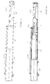
- the combined mast is in its position the most folded.
- the auxiliary mast is fully engaged in the mast main, the V-MA mast extension cylinder being retracted.
- FL arrow is itself retracted into the auxiliary mast and the balance is in position elongated, almost completely retracted into the auxiliary mast at the following the arrow FL.
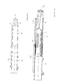
- Figure 8 shows a position of the elements of the combined mast to which we arrive after deployment of the boom and pendulum: the auxiliary mast MA has always returned to the main mast MP but the arrow FL was taken out by the cylinder V-FL and the BA balance is still in the alignment of the arrow FL.
- Figure 10 shows a position that can be reached at from the position of figure 9.
- the auxiliary mast MA is out, the arrow FL is out and the pendulum BA is in the extended position.
- the transition from the position of Figure 9 to that of Figure 10 is done by deployment of the V-MA mast extension cylinder, the other elements of the combined mast having kept the position they had in Figure 9.
- FIG. 10A shows in section the auxiliary mast MA, the arrow FL and BA pendulum. This figure shows the deployment of the cylinder mast extension V-MA and the boom extension cylinder V-FL. These two cylinders are deployed while the V-BA balance cylinder is in retracted position as well as the V-TPO tilt cylinder.
- Figure 11 shows a different position than that of Figure 10 but which is obtained from the position of FIG. 9.
- the auxiliary mast MA is retracted, the arrow FL is extended and the BA balance is in an intermediate position, tilted around its axis of articulation 20 with the arrow FL by the control of the V-BA balance cylinder.
- the tilt cylinder has not changed.
- Figure 11A shows the arrangement of parts according to the figure 11, in section.
- Figure 12 shows a position obtained from that in Figure 11: the BA balance has been put into the folded position by the control of the V-BA balance cylinder. The other elements of the combined mast have retained their position.
- Figure 12A shows in section the arrangement of the different elements constituting the combined mast, for the position shown in the figure 12.
- Figure 13 shows a position that can be reached at from the position of figure 11 but after deployment of the jack extension of the V-MA mast, the other elements having retained their position.
- Figure 13A shows in section the position of the parts of the mast according to figure 13.
- Figure 14 shows the pendulum more folded in relation to the position of Figure 13.
- the mast is deployed, the auxiliary mast MA being got out ; the arrow FL is out and the pendulum BA is in the folded position.
- Figure 14A is a sectional view showing the arrangement parts according to figure 14.
- Figure 15 is a sectional view showing the position retraction of the boom FL and of the pendulum BA but after deployment of the mast auxiliary MA with respect to the main mast MP by the extension cylinder of the V-MA mast.
- the different cylinders of the combined mast are powered by hydraulic circuits connected to a command control managing the operation according to the possibilities of the tool installed at the end combined mast and authorized movements of the different components of the combined mast.
- Prohibitions include, for example, the prohibition of the V-TPO tilt cylinder when the balance is still engaged in the MA auxiliary mast.
- This management of the functions of the combined mast also account of mast lifting movements and pivoting of the mast around of a vertical axis.
Landscapes
- Engineering & Computer Science (AREA)
- Mechanical Engineering (AREA)
- Mining & Mineral Resources (AREA)
- Civil Engineering (AREA)
- General Engineering & Computer Science (AREA)
- Structural Engineering (AREA)
- Jib Cranes (AREA)
Applications Claiming Priority (2)
| Application Number | Priority Date | Filing Date | Title |
|---|---|---|---|
| FR0212400 | 2002-10-07 | ||
| FR0212400A FR2845405B1 (fr) | 2002-10-07 | 2002-10-07 | Mat combine pour un engin de chantier |
Publications (2)
| Publication Number | Publication Date |
|---|---|
| EP1408162A1 true EP1408162A1 (de) | 2004-04-14 |
| EP1408162A8 EP1408162A8 (de) | 2004-08-18 |
Family
ID=32011445
Family Applications (1)
| Application Number | Title | Priority Date | Filing Date |
|---|---|---|---|
| EP03292444A Withdrawn EP1408162A1 (de) | 2002-10-07 | 2003-10-03 | Mastanordnung für eine Baumaschine |
Country Status (2)
| Country | Link |
|---|---|
| EP (1) | EP1408162A1 (de) |
| FR (1) | FR2845405B1 (de) |
Cited By (1)
| Publication number | Priority date | Publication date | Assignee | Title |
|---|---|---|---|---|
| IT202300003855A1 (it) * | 2023-03-03 | 2024-09-03 | Gl 1 S R L | Macchina agricola con braccio telescopico |
Citations (6)
| Publication number | Priority date | Publication date | Assignee | Title |
|---|---|---|---|---|
| US2984373A (en) * | 1958-07-16 | 1961-05-16 | Warner Swasey Co | Material handling apparatus |
| US4674944A (en) * | 1985-12-27 | 1987-06-23 | Kidde, Inc. | Forklift variable reach mechanism |
| US4822237A (en) * | 1985-11-21 | 1989-04-18 | The Gradall Company | Extended reach materials handling apparatus |
| FR2648122A1 (fr) * | 1989-06-09 | 1990-12-14 | Manitou Costruzioni Ind | Dispositif de bras telescopique pour chariot elevateur |
| US5494397A (en) * | 1992-01-20 | 1996-02-27 | Caterpillar Inc. | Load handling apparatus |
| EP0960981A2 (de) * | 1998-05-29 | 1999-12-01 | Spitznas Maschinenfabrik GmbH | Mobiles Arbeitsgerät und Bausatz für einen Arbeitsarm für ein mobiles Arbeitsgerät |
-
2002
- 2002-10-07 FR FR0212400A patent/FR2845405B1/fr not_active Expired - Fee Related
-
2003
- 2003-10-03 EP EP03292444A patent/EP1408162A1/de not_active Withdrawn
Patent Citations (6)
| Publication number | Priority date | Publication date | Assignee | Title |
|---|---|---|---|---|
| US2984373A (en) * | 1958-07-16 | 1961-05-16 | Warner Swasey Co | Material handling apparatus |
| US4822237A (en) * | 1985-11-21 | 1989-04-18 | The Gradall Company | Extended reach materials handling apparatus |
| US4674944A (en) * | 1985-12-27 | 1987-06-23 | Kidde, Inc. | Forklift variable reach mechanism |
| FR2648122A1 (fr) * | 1989-06-09 | 1990-12-14 | Manitou Costruzioni Ind | Dispositif de bras telescopique pour chariot elevateur |
| US5494397A (en) * | 1992-01-20 | 1996-02-27 | Caterpillar Inc. | Load handling apparatus |
| EP0960981A2 (de) * | 1998-05-29 | 1999-12-01 | Spitznas Maschinenfabrik GmbH | Mobiles Arbeitsgerät und Bausatz für einen Arbeitsarm für ein mobiles Arbeitsgerät |
Cited By (1)
| Publication number | Priority date | Publication date | Assignee | Title |
|---|---|---|---|---|
| IT202300003855A1 (it) * | 2023-03-03 | 2024-09-03 | Gl 1 S R L | Macchina agricola con braccio telescopico |
Also Published As
| Publication number | Publication date |
|---|---|
| FR2845405A1 (fr) | 2004-04-09 |
| FR2845405B1 (fr) | 2004-12-17 |
| EP1408162A8 (de) | 2004-08-18 |
Similar Documents
| Publication | Publication Date | Title |
|---|---|---|
| FR2493820A1 (fr) | Grue autotractee equipee de supports deployables commandes hydrauliquement et electriquement, et mecanisme de verrouillage associe auxdits supports | |
| EP0733584A1 (de) | Automatische Aufrichtvorrichtung für einen Kran mit zusammenklappbarem Ausleger | |
| FR2825106A1 (fr) | Excavatrice a guidage de tubes hydrauliques | |
| EP3184481B1 (de) | Turmkran mit automatischer ein- und ausklappfunktion, der einen mast und einen zum mast versetzten ausleger umfasst | |
| FR2993904A1 (fr) | Chargeur frontal | |
| US9181678B2 (en) | Backhoe loader | |
| EP1408162A1 (de) | Mastanordnung für eine Baumaschine | |
| FR2765564A1 (fr) | Mature pliable en trois elements avec dispositif de pliage/depliage pour grue a tour | |
| FR2532671A1 (fr) | Chargeur-excavateur a un seul equipement de travail | |
| CA2378609A1 (fr) | Appareil de manutention d'une charge et vehicule le comportant | |
| EP1072553A1 (de) | Zusammenklappvorrichtung eines Kranauslegers mit ineinandersetzbaren Elementen | |
| EP1607363A2 (de) | Kran mit einem teleskopierbarem Ausleger | |
| FR2813212A1 (fr) | Rampe de pulverisation perfectionnee | |
| EP0873964B1 (de) | Technik zum Aufrichten des Mastes für einen Teleskopkran | |
| FR2493818A1 (fr) | Grue autotractee equipee de supports deployables de stabilisation et de jambes de force mobiles verticalement associees a ces derniers, et support deployable ainsi realise | |
| WO1979001075A1 (fr) | Engin polyvalent de terrassement et de manutention | |
| FR2536735A1 (fr) | Chariot de travail notamment pour la pose des vitres de toitures des serres agricoles | |
| FR2869195A1 (fr) | Machine pour effectuer des travaux de fauchage/ debroussaillage et d'elagage | |
| FR2615157A1 (fr) | Tracteur perfectionne notamment pour semi-remorque | |
| FR2520715A1 (fr) | Chariot elevateur a bras telescopiques articules | |
| EP1352870B1 (de) | Vorrichtung zum Anheben und Aufklappen von dem Mast und zum Anheben von dem Ausleger eines Kranes | |
| FR2645520A1 (fr) | Structure de levage telescopique pour un engin tel qu'une chargeuse | |
| FR2759998A1 (fr) | Engin porte-outil pour le transport, la manutention et l'execution de travaux avec des outils | |
| FR2814038A1 (fr) | Dispositif de relevage pour tracteur permettant d'atteler et de deteler une masse sans intervention manuelle | |
| EP0113266A1 (de) | Kombiniertes Kraftfahrzeug, insbesondere mit Bagger ausgerüsteter leichter Lastkraftwagen für schnellen Einsatz |
Legal Events
| Date | Code | Title | Description |
|---|---|---|---|
| PUAI | Public reference made under article 153(3) epc to a published international application that has entered the european phase |
Free format text: ORIGINAL CODE: 0009012 |
|
| AK | Designated contracting states |
Kind code of ref document: A1 Designated state(s): AT BE BG CH CY CZ DE DK EE ES FI FR GB GR HU IE IT LI LU MC NL PT RO SE SI SK TR |
|
| AX | Request for extension of the european patent |
Extension state: AL LT LV MK |
|
| RAP1 | Party data changed (applicant data changed or rights of an application transferred) |
Owner name: COEURET, BERNARD |
|
| RIN1 | Information on inventor provided before grant (corrected) |
Inventor name: COEURET, BERNARD |
|
| 17P | Request for examination filed |
Effective date: 20040927 |
|
| AKX | Designation fees paid |
Designated state(s): AT BE BG CH CY CZ DE DK EE ES FI FR GB GR HU IE IT LI LU MC NL PT RO SE SI SK TR |
|
| STAA | Information on the status of an ep patent application or granted ep patent |
Free format text: STATUS: THE APPLICATION IS DEEMED TO BE WITHDRAWN |
|
| 18D | Application deemed to be withdrawn |
Effective date: 20080501 |