EP1408167A2 - Unité de construction transportable pour la protection d'une unité de transmission ou des dispositifs electroniques similaires - Google Patents
Unité de construction transportable pour la protection d'une unité de transmission ou des dispositifs electroniques similaires Download PDFInfo
- Publication number
- EP1408167A2 EP1408167A2 EP02027330A EP02027330A EP1408167A2 EP 1408167 A2 EP1408167 A2 EP 1408167A2 EP 02027330 A EP02027330 A EP 02027330A EP 02027330 A EP02027330 A EP 02027330A EP 1408167 A2 EP1408167 A2 EP 1408167A2
- Authority
- EP
- European Patent Office
- Prior art keywords
- wall
- cell according
- frame
- roof
- edge
- Prior art date
- Legal status (The legal status is an assumption and is not a legal conclusion. Google has not performed a legal analysis and makes no representation as to the accuracy of the status listed.)
- Withdrawn
Links
Images



Classifications
-
- E—FIXED CONSTRUCTIONS
- E04—BUILDING
- E04B—GENERAL BUILDING CONSTRUCTIONS; WALLS, e.g. PARTITIONS; ROOFS; FLOORS; CEILINGS; INSULATION OR OTHER PROTECTION OF BUILDINGS
- E04B1/00—Constructions in general; Structures which are not restricted either to walls, e.g. partitions, or floors or ceilings or roofs
- E04B1/02—Structures consisting primarily of load-supporting, block-shaped, or slab-shaped elements
- E04B1/04—Structures consisting primarily of load-supporting, block-shaped, or slab-shaped elements the elements consisting of concrete, e.g. reinforced concrete, or other stone-like material
-
- E—FIXED CONSTRUCTIONS
- E04—BUILDING
- E04H—BUILDINGS OR LIKE STRUCTURES FOR PARTICULAR PURPOSES; SWIMMING OR SPLASH BATHS OR POOLS; MASTS; FENCING; TENTS OR CANOPIES, IN GENERAL
- E04H1/00—Buildings or groups of buildings for dwelling or office purposes; General layout, e.g. modular co-ordination or staggered storeys
- E04H1/12—Small buildings or other erections for limited occupation, erected in the open air or arranged in buildings, e.g. kiosks, waiting shelters for bus stops or for filling stations, roofs for railway platforms, watchmen's huts or dressing cubicles
- E04H1/1205—Small buildings erected in the open air
- E04H1/1238—Shelters for engines, e.g. electrical meter housings
Definitions
- the invention relates to a portable room cell for Protection of a transmitter system or other electrical engineering Devices with wall elements protruding from a base plate and a roof placed on it and with ventilation openings in at least one cell wall.
- Transmitter systems or corresponding electrotechnical devices generate relatively high power losses, and their lifespan depends on certain limit temperatures that must not be exceeded.
- the applicant has up to 4 kW for dissipating heat losses developed its own ventilation concept for concrete room cells, that works without an air conditioner and only - relatively rarely - when high outside temperatures use a built-in fan required.
- This is on the door side a fan element measuring 52 cm x 64 cm built in, which contains a filter mat.
- For the exhaust air are provided near the roof ventilation slots, as in a Embodiment of DE 197 06 320 A1 from the applicant are.
- the temperature inside the station is over 45 ° C rises, turns on in the opposite Wall-mounted fan - for a recess diameter of 34.5 cm - a, whereby as a supply air cross section both the supply air fan element with filter mat as well Ventilation slots.
- the inventor was aware of this state of the art set the goal of a room cell for such purposes to improve so that their handling is simplified as well as transport and installation also to or on high-rise buildings is made possible.
- the walls each consist of a frame or scaffold and one piece connected to it Wall shell; these walls are non-positive with the base plate designed to be connectable.
- Wall and base plate are advantageously one on a single formwork producible cassette plate.
- the frame or the Scaffold the wall a floor-level longitudinal profile, one in short Distance from the top edge of the ridge and this connecting vertical profiles.
- the frame or the Scaffold the wall should be on each side edge of the wall from the floor Vertical profile running along the top edge of the wall be molded on.
- the thickness of the vertical and horizontal profiles at most 100 mm, monolithically connected to the frame or scaffold Wall shell is at most 30 mm thick.
- a thin-walled infill of the walls between the frame or scaffolding has a maximum area dimension of 250 cm Have height and 100 cm width.
- ridge profile to form all-round frame-like reinforcement, so that between this and the top of the wall in the thin-walled Filling out cable entries, ventilation elements or the like. able to be inserted, especially one All-round ventilation between the ridge profile and the top edge of the wall.
- the base plate has a frame edge-side floor webs and longitudinal webs connecting them on which is integral to an inner plate section are formed to a small thickness; the wall becomes with the floor Part of their frame or scaffold into a step-like Edge cutout of the base plate - or of its edge ridges - inserted and with the base plate non-positively connected.
- the vertical Stop surface of the edge cutout of the base plate as well provide the adjacent outer surface with sleeves for screws his; the wall is in turn in the area of the floor Longitudinal profile of screws designed to be enforceable; these are arranged so that they fit into the sleeves of the Can engage floor plate.
- a floor bracket is provided as a further fastening aid whose leg of the outer surface of the base plate or the bottom face of which are in contact.
- the roof construction is of particular importance here; as Roof becomes a flat or saddle roof in lightweight construction the top edges of the wall laid on; the construction of the roof forms the upper fixation of the walls, while acting Forces - such as wind forces - from the roof structure recorded and over the entire construction in a foundation be initiated.
- This roof construction settles composed of profiles and sheets, preferably of one Aluminum alloy are molded.
- the roof structure on the inside with at least one heat-insulating Provide layer as well as by stand profiles on ridge profiles connected to the walls; with the stand profiles advantageously an overlying roof frame made of metal profiles connected. And between the stand profiles and the roof frame should have a perforated grille protruding from the roof edge can be arranged, which preferably all around the top of the wall rests.
- the end wall 18 In the middle of the end wall 18 there is an opening 22 with a width b 2 of approximately 90 cm for a fire-retardant front door 24 which is suspended in a frame 23 and is flanked on both sides by a narrow opening 25 for a ventilation element 26.
- the rear wall 16 contains, near the upper wall edge 20 - below a rectangular wall recess 28 - a circular opening 29 for a fan indicated at 30.
- Each of the walls 14, 16, 18 formed monolithically from fiber concrete has a base profile 32 with a square cross-section at the bottom and, at a central distance h 1 of about 205 cm, an equally shaped ridge profile 32 a , both of which are connected by four vertical profiles 33, 33 a and with them form a frame structure of that thickness e for a thin cassette plate as infill wall shell 34; whose thickness e 1 measures less than 30 mm.
- the molded on the two side edges of each wall 14, 16, 18 vertical profile 33 extends from the base profile 32 to the upper wall edge 20.
- Those ridge profiles 32 a form in the room cell 10 at a central distance h 2 of about 25 cm to the upper wall edges 20 of circumferential frame-like reinforcements that make it possible above in the thin-walled cassette plate 34 of the walls 14, 16, 18 cable entries, ventilation elements or the like. to install. 4, 10 in particular, horizontal slots 36 for exhaust air can be seen in the side walls 14; the design of such ventilation slots 36 can be found, for example, in EP 0 103 221 B1 by the applicant. Below the ventilation slots 36, cabinets 90 of the length k of, for example, 120 cm and the width K 1 of 60 cm for electrical systems are indicated in FIGS. 9 to 11.
- the walls 14, 16, 18 described are in one piece with a single formwork cassette elements that can are positively connected to each other; the upper fixation the walls 14, 16, 18 is achieved by a gable roof 40; this roof 40 is made of an aluminum construction thermally insulated and lies on the upper wall edge 20.
- the roof 40 can in a design not shown as a flat roof be trained.
- the roof 40 has a roof frame 44 - connected to the walls 14, 16, 18 by press-in nuts 42 - made of two inner profiles 45 of length g of 160 cm and four outer frame profiles 46 and 46 a of length i from 220 cm or i 1 from 200 cm; these frame profiles 46, 46 a overlap one another at the actual frame corners 44 e by means of cantilever sections 46 e of the free length i 2 of 16 cm projecting from the latter.
- outer profiles 48 and 48 a of length i 3 of about 190 cm and i 4 of about 168 cm are defined, which run at a distance parallel to the frame profiles 46, 46 a ; additional connecting profiles of the cantilever length i 2 mentioned between adjacent profiles 46/48 or 46 a / 48 a are denoted by 49. 6, 15 that the upper wall edge 20 of the side wall 14 runs in the region of the cantilever sections 46 e near their free ends.
- the roof frame 44 described is supported by two roof plates 52 inclined downwards like a desk at an angle w of approximately 7 ° from a ridge line 50 which runs at a vertical distance f of 24 mm from the lower frame surface. These are provided on the inside with insulation boards 38 with a thickness f 1 of approximately 20 cm and laterally overlap the base area given by the walls 14, 16, 18; they lie on those outer profiles 48.
- the profiles 46, 46 a and 48, 48 a indicated by way of example in FIG. 15 are extruded hollow profiles of an aluminum alloy with a square outline of the outer side length z of 40 mm and with the ridge profiles 32 a of the associated side wall 14 - or the rear or end wall 16, 18 - connected by vertical stand profiles 55 of length z 1 of approximately 30 cm and width y of 10 cm by screws 58.
- the upright profiles are of rectangular cross-section with two side legs 56 and one end plate 57, otherwise they have only one side leg 56 on the end plate 57, as shown in FIG. 16, below.
- the distance n of the inner surface 19 of the wall 14 from the longitudinal axis A of the frame profile 46 is 55 mm here.
- the vertical end wall 18 rests - like the other walls 14, 16 accordingly - in an edge cutout 70 of height and width c 1 of 70 mm of a bottom web 72 of free height c 3 of 120 which is formed like a bead on the outer edge mm and the foot width b 3 of 120 mm - the base plate 12 and is connected there to the base plate 12 or the vertical stop surface 71 of the edge cutout 70 by screws 58 a .
- the distance h 2 from its longitudinal axis B to the end face 73 of the bottom web 72 measures here 115 mm.
- the length a 1 of the base plate 12 sketched in FIGS. 19, 20 in the example shown measures approximately 210 cm parallel to the center line M of the room cell 10 with a width b 1 of 190 cm.
- the two above-mentioned floor webs 72 are supplemented by a longitudinal frame web 74, which is also molded onto the inner plate section 13 with a thickness c 4 of 30 mm, to form a floor frame; parallel to the longitudinal webs 74 runs in the center line M a foot strip 76 of floor width b 4 of 10 cm, which delimits a channel space 75 of width b 5 of about 850 mm with each longitudinal web 74.
- the side surfaces of the webs 72, 74 and the foot strip 76 are also inclined toward the end or bottom surfaces 73, tapering in cross-section downwards.
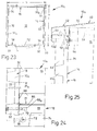
- the threshold edge of the opening 22 is designated by 21 in FIG. 24, the upper edge of which is 21 a .
- the surface of the base plate 12 is spanned here by a linoleum covering 86 on which a skirting 88 on the wall is seated.
- 25 is connected to the lateral roof edge 53 in FIG. 25 a connecting plate 51 which is bent in opposite directions on the longitudinal edges and which sits on the upper wall edge 20 and on the inside strikes a screw angle 64; this is screwed to the side wall 14 here.
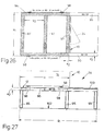
- the space cell 10, 10 a described above can also be non-positively fixed on a steel structure 94 outlined in FIGS. 26 to 29, in particular if the flat roof of a high-rise building indicated in FIG. 27, 28 is to serve as the installation site.
- Two longitudinal rails or profiles 96 lying on vertical upright profiles 95 and having a length g 1 of 330 cm and a height and width e 2 of 12 cm are made into a platform 94 of width y 1 by three cross profiles 97 spaced g 2 of about 85 cm connected by about 190 cm.
- the room cell 10 is placed on the section determined by the transverse profiles 97 and is screwed to steel steel plates 99 by means of steel plates 98 vertically welded to the longitudinal rails 96 - comparable to the counter angles 81 mentioned; To improve the adhesion, wedge plates 99 a are introduced. The footprint is hatched out in Fig. 26.
- a grating 100 is placed in front of the end wall 18 of the room cell 10 as a platform.
- a typical room cell 10, 10 a offers a built-up area of approximately 4.20 m 2 , a usable area of approximately 3.50 m 2 and a built-up area of approximately 10.70 m 3 if fiber concrete is required of approximately 0.95 m 3 ; the total weight of the concrete parts is only about 22.75 KN.
Landscapes
- Engineering & Computer Science (AREA)
- Architecture (AREA)
- Civil Engineering (AREA)
- Structural Engineering (AREA)
- Physics & Mathematics (AREA)
- Electromagnetism (AREA)
- Building Environments (AREA)
- On-Site Construction Work That Accompanies The Preparation And Application Of Concrete (AREA)
- Load-Bearing And Curtain Walls (AREA)
Applications Claiming Priority (2)
| Application Number | Priority Date | Filing Date | Title |
|---|---|---|---|
| DE20215395U DE20215395U1 (de) | 2002-10-07 | 2002-10-07 | Transportable Raumzelle zum Schutz einer Senderanlage oder anderer elektronischer Geräte |
| DE20215395U | 2002-10-07 |
Publications (2)
| Publication Number | Publication Date |
|---|---|
| EP1408167A2 true EP1408167A2 (fr) | 2004-04-14 |
| EP1408167A3 EP1408167A3 (fr) | 2005-03-23 |
Family
ID=7975757
Family Applications (1)
| Application Number | Title | Priority Date | Filing Date |
|---|---|---|---|
| EP02027330A Withdrawn EP1408167A3 (fr) | 2002-10-07 | 2002-12-07 | Unité de construction transportable pour la protection d'une unité de transmission ou des dispositifs electroniques similaires |
Country Status (2)
| Country | Link |
|---|---|
| EP (1) | EP1408167A3 (fr) |
| DE (1) | DE20215395U1 (fr) |
Cited By (3)
| Publication number | Priority date | Publication date | Assignee | Title |
|---|---|---|---|---|
| CN109980565A (zh) * | 2019-04-10 | 2019-07-05 | 河南发明哥知识产权代理有限公司 | 一种基于物联网端的可远程维护箱变 |
| CN117261639A (zh) * | 2023-09-28 | 2023-12-22 | 河北新大长远电力科技股份有限公司 | 一种针对电动汽车充电站基础设备 |
| AT527489A4 (de) * | 2023-12-31 | 2025-03-15 | Lisa Maria Rosenich Msc | Tiny-Haus-Befestigungseinrichtung |
Families Citing this family (1)
| Publication number | Priority date | Publication date | Assignee | Title |
|---|---|---|---|---|
| FR2925541B1 (fr) * | 2007-12-21 | 2013-08-02 | David Damichey | Element prefabrique pour unite d'habitation. |
Family Cites Families (9)
| Publication number | Priority date | Publication date | Assignee | Title |
|---|---|---|---|---|
| DE1942718U (de) * | 1966-05-11 | 1966-07-21 | Hans Rommel | Zusammenlegbares, transportables kleinhaus. |
| DE2110089C3 (de) * | 1971-03-03 | 1974-04-04 | Gervin 6833 Kirrlach Mueller | Explosionsgefährdetes, im wesentlichen einzelliges Gebäude |
| FR2302395A1 (fr) * | 1975-02-28 | 1976-09-24 | Auxiliaire Entreprises Soc | Procede de construction de maisons individuelles a partir de |
| CH643315A5 (en) * | 1979-10-08 | 1984-05-30 | Hans Scheidl | Prefabricated unitised unit |
| DE8612429U1 (de) * | 1986-05-06 | 1986-06-26 | Gebrüder Marx Verwaltungsgesellschaft mbH, Betonwerk GmbH & Co KG, 35510 Butzbach | Aus Beton bestehende Raumzelle |
| ATE139817T1 (de) * | 1992-03-31 | 1996-07-15 | Betonbau Gmbh | Transportable raumzelle und verfahren zum herstellen einer raumzelle |
| BE1010092A6 (fr) * | 1996-04-05 | 1997-12-02 | Louis Marc | Procede de fabrication et d'assemblage d'un element de contruction en beton. |
| EP0974705A1 (fr) * | 1998-07-24 | 2000-01-26 | Alho Systembau GmbH | Cellule de bâtiment démontable |
| EP1162322B1 (fr) * | 2000-06-07 | 2004-08-04 | ALHO-Systembau GmbH Sörnewitz | Cellule de bâtiment démontable |
-
2002
- 2002-10-07 DE DE20215395U patent/DE20215395U1/de not_active Expired - Lifetime
- 2002-12-07 EP EP02027330A patent/EP1408167A3/fr not_active Withdrawn
Cited By (4)
| Publication number | Priority date | Publication date | Assignee | Title |
|---|---|---|---|---|
| CN109980565A (zh) * | 2019-04-10 | 2019-07-05 | 河南发明哥知识产权代理有限公司 | 一种基于物联网端的可远程维护箱变 |
| CN117261639A (zh) * | 2023-09-28 | 2023-12-22 | 河北新大长远电力科技股份有限公司 | 一种针对电动汽车充电站基础设备 |
| AT527489A4 (de) * | 2023-12-31 | 2025-03-15 | Lisa Maria Rosenich Msc | Tiny-Haus-Befestigungseinrichtung |
| AT527489B1 (de) * | 2023-12-31 | 2025-03-15 | Lisa Maria Rosenich Msc | Tiny-Haus-Befestigungseinrichtung |
Also Published As
| Publication number | Publication date |
|---|---|
| DE20215395U1 (de) | 2003-03-13 |
| EP1408167A3 (fr) | 2005-03-23 |
Similar Documents
| Publication | Publication Date | Title |
|---|---|---|
| DE1941281C3 (de) | Bauwerk | |
| DE2907630C2 (fr) | ||
| EP2762763B1 (fr) | Structure de cadre pour le montage d'une cabine d'isolation phonique | |
| EP1108828A1 (fr) | Cage d'ascenseur | |
| DE2720198C3 (de) | Aus tragenden Containern modulartig zusammengesetztes Gebäude | |
| EP0639677B1 (fr) | Bâtiment composé par des modules de cellules préfabriquées | |
| DE4020962A1 (de) | Raumzelle | |
| EP1408167A2 (fr) | Unité de construction transportable pour la protection d'une unité de transmission ou des dispositifs electroniques similaires | |
| DE3122593C2 (fr) | ||
| DE202014000276U1 (de) | Balkonsystem | |
| DE2514820C3 (de) | Stützkonstruktion für hölzerne Sparren mit im Bereich der Traufkante angeordneten Traufböcken | |
| AT399185B (de) | Transportables gehäuse, insbesondere raumzelle, für eine umform- und/oder schaltstation, eine gasdruckregelstation, garage od.dgl. | |
| DE4204638A1 (de) | Vorrichtung zur schalldaemmung in raeumen | |
| EP0631022A2 (fr) | Elément tridimensionnel pour la construction d'ouvrages et procédé pour sa fabrication | |
| DE19957090B4 (de) | Fertigteil-Stallgebäude | |
| DE202010005576U1 (de) | Wandkonstruktion | |
| DE804860C (de) | Transportables Gewaechshaus o. dgl. | |
| DE1609536A1 (de) | Stahlskelett fuer ein mehrstoeckiges Haus | |
| DE29805353U1 (de) | Balkon-Bausatz | |
| DE2900172A1 (de) | Gebaeude | |
| DE2900171A1 (de) | Tragende wandelemente fuer gebaeude und diese enthaltendes gebaeude | |
| DE202015106821U1 (de) | Personennotunterkunft | |
| DE2028575B2 (de) | Gebäude, insbesondere fur Wohn zwecke | |
| DE9406399U1 (de) | Gerüst | |
| AT147382B (de) | Ein- oder mehrgeschossige Bauanlage. |
Legal Events
| Date | Code | Title | Description |
|---|---|---|---|
| PUAI | Public reference made under article 153(3) epc to a published international application that has entered the european phase |
Free format text: ORIGINAL CODE: 0009012 |
|
| AK | Designated contracting states |
Kind code of ref document: A2 Designated state(s): AT BE BG CH CY CZ DE DK EE ES FI FR GB GR IE IT LI LU MC NL PT SE SI SK TR |
|
| AX | Request for extension of the european patent |
Extension state: AL LT LV MK RO |
|
| PUAL | Search report despatched |
Free format text: ORIGINAL CODE: 0009013 |
|
| AK | Designated contracting states |
Kind code of ref document: A3 Designated state(s): AT BE BG CH CY CZ DE DK EE ES FI FR GB GR IE IT LI LU MC NL PT SE SI SK TR |
|
| AX | Request for extension of the european patent |
Extension state: AL LT LV MK RO |
|
| RIC1 | Information provided on ipc code assigned before grant |
Ipc: 7E 04B 1/348 B Ipc: 7E 04B 1/343 A |
|
| AKX | Designation fees paid | ||
| REG | Reference to a national code |
Ref country code: DE Ref legal event code: 8566 |
|
| STAA | Information on the status of an ep patent application or granted ep patent |
Free format text: STATUS: THE APPLICATION IS DEEMED TO BE WITHDRAWN |
|
| 18D | Application deemed to be withdrawn |
Effective date: 20050924 |