EP1408201A2 - Verfahren zur Inspektion von Dampfturbinen - Google Patents
Verfahren zur Inspektion von Dampfturbinen Download PDFInfo
- Publication number
- EP1408201A2 EP1408201A2 EP03022981A EP03022981A EP1408201A2 EP 1408201 A2 EP1408201 A2 EP 1408201A2 EP 03022981 A EP03022981 A EP 03022981A EP 03022981 A EP03022981 A EP 03022981A EP 1408201 A2 EP1408201 A2 EP 1408201A2
- Authority
- EP
- European Patent Office
- Prior art keywords
- component part
- target component
- data
- turbine
- steam
- Prior art date
- Legal status (The legal status is an assumption and is not a legal conclusion. Google has not performed a legal analysis and makes no representation as to the accuracy of the status listed.)
- Granted
Links
Images



Classifications
-
- G—PHYSICS
- G01—MEASURING; TESTING
- G01N—INVESTIGATING OR ANALYSING MATERIALS BY DETERMINING THEIR CHEMICAL OR PHYSICAL PROPERTIES
- G01N21/00—Investigating or analysing materials by the use of optical means, i.e. using sub-millimetre waves, infrared, visible or ultraviolet light
- G01N21/84—Systems specially adapted for particular applications
- G01N21/88—Investigating the presence of flaws or contamination
- G01N21/8803—Visual inspection
-
- F—MECHANICAL ENGINEERING; LIGHTING; HEATING; WEAPONS; BLASTING
- F01—MACHINES OR ENGINES IN GENERAL; ENGINE PLANTS IN GENERAL; STEAM ENGINES
- F01D—NON-POSITIVE DISPLACEMENT MACHINES OR ENGINES, e.g. STEAM TURBINES
- F01D21/00—Shutting-down of machines or engines, e.g. in emergency; Regulating, controlling, or safety means not otherwise provided for
- F01D21/003—Arrangements for testing or measuring
-
- G—PHYSICS
- G01—MEASURING; TESTING
- G01N—INVESTIGATING OR ANALYSING MATERIALS BY DETERMINING THEIR CHEMICAL OR PHYSICAL PROPERTIES
- G01N29/00—Investigating or analysing materials by the use of ultrasonic, sonic or infrasonic waves; Visualisation of the interior of objects by transmitting ultrasonic or sonic waves through the object
- G01N29/04—Analysing solids
- G01N29/043—Analysing solids in the interior, e.g. by shear waves
-
- G—PHYSICS
- G01—MEASURING; TESTING
- G01N—INVESTIGATING OR ANALYSING MATERIALS BY DETERMINING THEIR CHEMICAL OR PHYSICAL PROPERTIES
- G01N29/00—Investigating or analysing materials by the use of ultrasonic, sonic or infrasonic waves; Visualisation of the interior of objects by transmitting ultrasonic or sonic waves through the object
- G01N29/04—Analysing solids
- G01N29/11—Analysing solids by measuring attenuation of acoustic waves
-
- G—PHYSICS
- G01—MEASURING; TESTING
- G01N—INVESTIGATING OR ANALYSING MATERIALS BY DETERMINING THEIR CHEMICAL OR PHYSICAL PROPERTIES
- G01N29/00—Investigating or analysing materials by the use of ultrasonic, sonic or infrasonic waves; Visualisation of the interior of objects by transmitting ultrasonic or sonic waves through the object
- G01N29/14—Investigating or analysing materials by the use of ultrasonic, sonic or infrasonic waves; Visualisation of the interior of objects by transmitting ultrasonic or sonic waves through the object using acoustic emission techniques
-
- F—MECHANICAL ENGINEERING; LIGHTING; HEATING; WEAPONS; BLASTING
- F05—INDEXING SCHEMES RELATING TO ENGINES OR PUMPS IN VARIOUS SUBCLASSES OF CLASSES F01-F04
- F05D—INDEXING SCHEME FOR ASPECTS RELATING TO NON-POSITIVE-DISPLACEMENT MACHINES OR ENGINES, GAS-TURBINES OR JET-PROPULSION PLANTS
- F05D2260/00—Function
- F05D2260/80—Diagnostics
-
- G—PHYSICS
- G01—MEASURING; TESTING
- G01N—INVESTIGATING OR ANALYSING MATERIALS BY DETERMINING THEIR CHEMICAL OR PHYSICAL PROPERTIES
- G01N21/00—Investigating or analysing materials by the use of optical means, i.e. using sub-millimetre waves, infrared, visible or ultraviolet light
- G01N21/84—Systems specially adapted for particular applications
- G01N21/88—Investigating the presence of flaws or contamination
- G01N21/95—Investigating the presence of flaws or contamination characterised by the material or shape of the object to be examined
- G01N21/954—Inspecting the inner surface of hollow bodies, e.g. bores
-
- G—PHYSICS
- G01—MEASURING; TESTING
- G01N—INVESTIGATING OR ANALYSING MATERIALS BY DETERMINING THEIR CHEMICAL OR PHYSICAL PROPERTIES
- G01N2291/00—Indexing codes associated with group G01N29/00
- G01N2291/02—Indexing codes associated with the analysed material
- G01N2291/025—Change of phase or condition
- G01N2291/0258—Structural degradation, e.g. fatigue of composites, ageing of oils
-
- G—PHYSICS
- G01—MEASURING; TESTING
- G01N—INVESTIGATING OR ANALYSING MATERIALS BY DETERMINING THEIR CHEMICAL OR PHYSICAL PROPERTIES
- G01N2291/00—Indexing codes associated with group G01N29/00
- G01N2291/02—Indexing codes associated with the analysed material
- G01N2291/028—Material parameters
- G01N2291/02836—Flow rate, liquid level
-
- G—PHYSICS
- G01—MEASURING; TESTING
- G01N—INVESTIGATING OR ANALYSING MATERIALS BY DETERMINING THEIR CHEMICAL OR PHYSICAL PROPERTIES
- G01N2291/00—Indexing codes associated with group G01N29/00
- G01N2291/10—Number of transducers
- G01N2291/102—Number of transducers one emitter, one receiver
-
- G—PHYSICS
- G01—MEASURING; TESTING
- G01N—INVESTIGATING OR ANALYSING MATERIALS BY DETERMINING THEIR CHEMICAL OR PHYSICAL PROPERTIES
- G01N2291/00—Indexing codes associated with group G01N29/00
- G01N2291/26—Scanned objects
- G01N2291/269—Various geometry objects
- G01N2291/2693—Rotor or turbine parts
Definitions
- the present invention relates to a method of inspecting a component part of an apparatus included in a steam turbine system.
- a steam turbine always has a possibility that damage occurs due to the aged degradation and erosion of the component parts.
- the turbine is inspected periodically to find damaged parts before the parts are damaged seriously.
- Principal component parts to be inspected periodically of the steam turbine include moving blades, nozzles, a rotor, casings of high and medium-pressure stage turbines, valves, and steam pipes. Most defects that occur in those principal parts are cracks and fissures due to fatigue or creep, and thickness reduction and breakage due to erosion. Although it is possible that cracks are formed in portions of an outer surface of a turbine casing on which stress is concentrated, most defects occur on surfaces of the component parts exposed to high temperature and steam and thus subjected to quality degradation, creep, thermal fatigue and erosion.
- the upper half casing is removed, and radial and axial clearances between the rotating and stationary component parts are measured. Then the rotor is hoisted, the rotor, the moving blades, the nozzles and the turbine casing are visually inspected for defects, erosion and cracks, and non-destructive inspection such as PT, MT or UT is carried out. Then it is judged whether the component parts should be repaired or replaced, and they are repaired or replaced if necessary. Then, the rotor is returned into the turbine casing, clearances are measured and adjusted, and the upper half casing is set in place.
- the risk of possible troubles is determined based on data on the degree of degradation of the material and stress distributions in the component part.
- the degree of degradation of the material is examined through replication, hardness measurement or electrochemical test.
- the stress distribution is estimated by minute analysis using a FEM (finite element method).
- consumed life i.e., creep damage and/or fatigue damage accumulated in the damaged parts
- consumed life i.e., creep damage and/or fatigue damage accumulated in the damaged parts
- remaining life which is dependent on the possibility of formation and development of cracks
- remaining life which is dependent on the possibility of formation and development of cracks
- the condition of the damaged part is determined based on the estimated remaining life, the risk level of the defect is determined and countermeasures to eliminate the defect are planed.
- estimation of stress distribution for the determination of the risk level of the defect takes time, and the estimated stress distribution is greatly dependent on a temperature boundary condition used by analysis by a FEM. Since most plants do not have sufficient data, and hence the accuracy of analysis by a FEM is not necessarily satisfactory. Consequently, the accuracy of determination of the risk level of a defect, such as a crack, found by visual inspection is limited.
- a non-disassembling inspection method has been proposed.
- the method does not open the casing and inserts a fiberscope or a CCD camera through the flanged end of a steam pipe into the turbine casing.
- This inspection method omits a step of opening the casing, and a step of adjusting the clearances between the casing and blades, which is inevitable when the turbine casing is opened.
- the fiberscope or the CCD camera is inserted into the turbine casing for inspection after the temperature of the interior of the turbine casing has dropped near to an ordinary temperature.
- this method also takes a considerable long time, and also has the problem on unsatisfactory accuracy of the risk level determination.
- the present invention has been made in view of the foregoing problems and it is therefore an object of the present invention to provide a turbine system inspecting method that can be carried out in a short time period and highly accurately, quickly achieve the determination of the risk level of an abnormality found by inspection.
- the inventive concept of the present invention is as follows.
- the target component part i.e., the component part to be inspected
- high temperature steam flows therethrough such as a turbine casing or a valve casing
- stresses are induced in the component part due to an internal steam pressure and a temperature distribution.
- internal-pressure-related stress the stress induced due to the internal steam pressure
- thermal stress the stress induced due to the temperature distribution
- component parts through which high-temperature steam flows of the steam turbine is designed such that the internal-pressure-related stress is lower than the thermal stress in order to limit damage due to creep to the least extent.
- the thermal stress has a great effect on the development of cracks in the component parts. Therefore, in order to determine the risk of cracks formed in such component parts accurately, it is very important to know the thermal stress induced in the cracked portion accurately.
- the crack is closed. If the thermal stress induced in the cracked portion is considerably high, the crack is opened.
- the dimension or the size of the opening of the crack closely relates to the thermal stress induced in the cracked portion.
- the thermal stress induced in the cracked portion which is difficult to calculate accurately only by a FEM, can be estimated with high accuracy based on the dimension or the size of the opening of the crack. Therefore, the risk level of the crack can accurately be determined by examining the dimension or the size of the opening of the crack when a thermal stress is induced in the cracked portion, preferably when a maximum thermal stress induced in the cracked portion.
- a maximum thermal stress is induced in the above component part, such as turbine casing, during starting-up and the shutting-down of the steam turbine system.
- the clearance between adjacent component parts is a very important parameter that determines the performance and efficiency of the turbine. Similar to the thermal stress as discussed above, the clearance is dependent on thermal expansion distribution in the component parts due to temperature distribution. Therefore, the risk level of the clearance can accurately be determined by measuring the clearance when the temperature of the component parts is distributed in a wide range.
- the inspection is performed when the atmospheric temperature of the internal space of the apparatus (e.g., a turbine and a valve) included in the turbine system is preferably not less than 100°C, more preferably 100°C to 300°C. It is also preferable that the inspection is performed when a time period in a range of 24 to 100 hours passes from the shutting-down of the turbine system. According to the above, the inspection can be carried out while the temperature distribution is wide enough.
- the atmospheric temperature of the internal space of the apparatus e.g., a turbine and a valve
- the inspection is performed when a time period in a range of 24 to 100 hours passes from the shutting-down of the turbine system. According to the above, the inspection can be carried out while the temperature distribution is wide enough.
- the component parts are not disassembled. This is because, upon disassembly, the component parts lose most of the thermal stress induced therein, and the clearance cannot be measured. In addition, the disassembly lengthens the inspection time.
- the present invention provides a method of inspecting a target component part of an apparatus included in a steam turbine system, the target component part being exposed to steam that flows through a space defined by an enclosing member of the apparatus when the steam turbine system is in normal operation.
- the method including the steps of: shutting down the steam turbine system which has been in normal operation; obtaining, after shutting down the turbine system, a first data by means of an inspecting device, the first data relating to a dimension of a crack formed in the target component part or relating to a clearance between the target component part and an adjacent component part arranged adjacent to the target component part, wherein the obtaining step is performed when a time period in a range of 24 to 100 hours passes from the shutting-down of the turbine system, or before an atmospheric temperature of the space is lowered to 100°C, and wherein the obtaining step is performed without disassembling the enclosing member and the target component part from the apparatus having the target component part; and judging whether the target component part should be repaired upon comparing the data with a judgmental standard, or comparing an output calculated by applying the data to a predetermined function with a judgmental standard.
- the step of obtaining the first data may be performed when the atmospheric temperature of the space is not more than 300°C.
- the method may further include a step of obtaining, after the step of obtaining the first data is performed, a second data by means of the inspecting device, the first data relating to a dimension of a crack formed in the target component part or relating to a clearance between the target component part and an adjacent component part arranged adjacent to the target component part, wherein the step of obtaining the second data is performed without disassembling the enclosing member and the target component part from the apparatus having the target component part, and wherein the judging step is performed by comparing at least one of the first data and the second data with a judgmental standard, or comparing an output calculated by applying at least one of the first data and the second data to a predetermined function with a judgmental standard.
- the first data relating to the clearance may be the clearance itself, a dimension of an eroded portion in the target component part or said adjacent component part, or a dimension of a scale layer formed on the target component part or said adjacent component part.
- the step of obtaining the first data may be performed with the inspecting device being inserted into the space through an insertion path extending through the enclosing member.
- the apparatus included in a steam turbine system is a turbine, and the enclosing element is a turbine casing; and the insertion path comprises a steam pipe for supplying or discharging the steam into or from the turbine when the turbine system is in the normal operation, or an opening exclusively formed in the turbine casing for insertion of the inspecting device.
- the inspecting device may comprise an image pick-up device adapted to pick up an image of the target component part.
- the image pick-up device may be a CCD camera, a fiberscope or the like.
- the target component part may be the enclosing member having an inner surface facing the space and an outer surface, and wherein the step of obtaining the first data may be performed with the inspecting device being attached to the outer surface of the enclosing member.
- the inspecting device may comprise a probe of an ultrasonic flaw detection apparatus.
- the apparatus included in the steam turbine system may be a valve for stopping or controlling a flow of the steam, and wherein the enclosing member may be a valve casing.
- the present invention relates to a method of inspecting a target component part (i.e., a component part to be inspected) of an apparatus included in a steam turbine system, the target component part being exposed to steam that flows through a space defined by an enclosing member of the apparatus when the steam turbine system is in normal operation.
- a target component part i.e., a component part to be inspected
- the apparatuses are a high-pressure steam turbine having a double-casing structure 2, and a valve 6 for controlling or stopping the flow of the steam (in this embodiment, a main stop valve (MSV));
- the target component parts are an inner turbine casing 2b and a moving blade 3 of the high-pressure steam turbine 1, and a valve casing 7 of the valve 6;
- the inspecting items are cracks formed in inner side of the inner turbine casing 2b and a valve casing 7, and a clearance between the tip of the moving blade 3 and the inner surface of the inner turbine casing 2b.
- the steam turbine system which has been in normal operation, stops or is shut down.
- a remote-controlled CCD camera 10 i.e., an image pickup device
- the predetermined time preferably 24 to 100 hours
- an atmospheric temperature of the interior space 4 of the turbine in the vicinity of the target component part is lowered to a predetermined temperature (preferably 100°C to 300°C).
- the CCD camera 10 has a device such as magnet rollers (not shown) that allows the CCD camera 10 to move on surfaces of the component parts of the turbine.
- the insertion of the CCD camera 10 is carried out without disassembling the turbine casings 2a and 2b, or overhauling the turbine 1.
- the CCD camera 10 is inserted into the interior space of the turbine casing 1 from the flanged end 5a of the steam pipe 5 through the steam pipe 5.
- the steam pipe 5 is divided for insertion of the CCD camera 10.
- the insertion route may be any one of those indicated by chain arrows shown in Fig. 1.
- the turbine may be provided with holes exclusively for insertion of the CCD camera 10, which may be formed in the wall of the steam pipe 5 or the turbine casing 2a, 2b, and which are sealingly closed when the turbine system is in normal operation.
- the image data obtained by the CCD camera 10 is sent to an image analyzer 11. If any crack is found, the dimension or size (e.g., width W and/or length L) of the opening of the crack (i.e., crack-opening dimension) is determined by image analysis. Alternatively, the crack-opening dimension may be calculated manually based on the displayed image.
- the dimension or size e.g., width W and/or length L
- the crack-opening dimension may be calculated manually based on the displayed image.
- a temperature sensor (not shown) is attached to the CCD camera 10 to measure the atmospheric temperature (i.e., inspection temperature) of the interior space 4 of the turbine 1 in the vicinity of the target component part.
- the data on the crack-opening dimension and the inspection temperature is sent or inputted to a computer 12. According to a predetermined procedure which will be described later, the computer 12 judges whether the cracked portion should be repaired based on the crack-opening dimension and the inspection temperature.
- the CCD camera 10 also picks up images of a gap between adjacent component parts, such as a tip of the moving blade 3 and an inner surface of the inner turbine casing 2b.
- the image data is sent to an image analyzer 11.
- the clearance between the component parts is determined by image analysis.
- the temperature sensor also measures the atmospheric temperature (i.e., inspection temperature) of the interior space of the turbine in the vicinity of the target component parts.
- the data on the clearance and the inspection temperature is sent or inputted to a computer 10. According to a predetermined procedure which will be described later, the computer 10 judges whether the clearance should be adjusted based on the measured clearance and the inspection temperature.
- the inspection of the valve casing 7 is carried out.
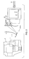
- a remote-controlled probe unit 21 of an ultrasonic flaw detection apparatus 20 (i.e., non-destructive inspection device) is attached onto an outer surface of the valve casing 7.
- the probe unit 21 has a pair of ultrasonic transducers 21a and 21b, one 21a for emitting an ultrasonic wave and the other 21b for receiving the reflected ultrasonic wave.
- the probe unit 21 has a device such as magnet rollers (not shown) that allows the probe unit 21 to move on the outer surface of the valve casing 7.
- the dimension of a crack, if any, formed in the valve casing is measured based on the wave pattern shown on a display 22.
- the data on the crack dimension and the inspection temperature is sent or inputted to the computer 12.
- the computer 12 judges whether the cracked portion should be repaired based on the crack dimension and the measured temperature.
- the atmospheric temperature may be estimated or calculated based on the temperature of the outer surface of the valve casing.
- the outer and inner casings 2a and 2b of the turbine 1 or the valve casing 7 are disassembled. Then, the cracked portion is repaired by a suitable conventional method, or the clearance is adjusted by a suitable conventional method.
- Fig. 3A is a graph showing the dependence of temperature difference between the interior and the exterior of a turbine casing on turbine internal temperature (i.e., atmospheric temperature of the interior space of the turbine casing where steam flows) after shutting-down of the turbine system.
- Fig. 3B is a graph showing the dependence of thermal stress on turbine internal temperature. The temperature difference and the thermal stress are high when the turbine internal temperature is in the range of 100°C to 300°C. The changes in the temperature difference and in the thermal stress shows similar tendency after starting-up of the turbine system.
- the turbine internal temperature is lowered to about 300°C when about 24 hours has elapsed from the shutting-down of the turbine system, and is lowered to about 100°C when about 100 hours has elapsed from the shutting-down of the turbine system.
- the change in the clearance is maximal when the turbine internal temperature is in the range of 100°C to 300°C.
- the valve casing shows a similar tendency.
- the inspection is preferably performed when the turbine internal temperature is in the range of 100°C to 300°C, or when a time period in a range of 24 to 100 hours passes from the shutting-down of the turbine system.
- Fig. 5 (a), (b) and (c) are graphs showing the dependence of sensitivity on temperature in visual inspection using a CCD camera or a fiberscope, inspection using a piezoelectric device (i.e., the probe of the ultrasonic flow detection apparatus), and inspection using both visual observation and a piezoelectric device.
- a CCD camera When a CCD camera is used, dew condenses on the lens of the CCD camera at temperatures not higher than 100°C to lower sensitivity. The measuring accuracy of a piezoelectric device drops sharply when the temperature increases beyond the Curie point.
- the inspection temperature should be not lower than 100°C. If the piezoelectric device is used for the inspection, the inspection temperature should be not higher than the Curie point, typically 300°C. If both devices are used, the temperature should be in the range of 100°C to 300°C, as shown in Fig. 5(c). However, some piezoelectric devices have Curie points higher than 300°C. In such a case, the inspection temperature may be higher than 300°C.
- the first judgment method is a very simple method.
- the computer includes a database in which a judgmental standard is stored, and judges whether the component part should be repaired based on the judgmental standard.
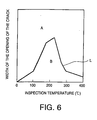
- the graph of Fig. 6 shows the judgmental standard.
- the data on the width of the opening of the crack (hereinafter referred to as "crack-opening width") and the inspection temperature is plotted on the graph. If the plot is in area A above line L, it is judged that the crack portion should be repaired. If the plot is in area B below line L, it is judged that the crack portion needs not be repaired.
- the graph may be prepared by minute analysis using a FEM.
- the judgmental standard for clearance may be prepared in a similar manner.
- the computer When the computer received the data on the crack-opening width and the inspection temperature (e.g., 150°C), the computer estimated a crack-opening width and the thermal stress induced in the cracked portion at a specific temperature (e.g., 280°C) at which a maximum thermal stress induced in the cracked portion.
- the computer applies the estimated thermal stress to a loading endurance limit diagrams for the material forming the cracked portion stored in the computer, in order to estimate the remaining life of the cracked portion based on the total operation time and/or the shutting-down and starting-up times of the turbine system. If the remaining life is not enough, the computer judges that the cracked portion should be repaired.
- the maximum thermal stress may be estimated or calculated by using simplified models, such as a cylindrical-shaped model for turbine casing, which are well-known in the technical field of materials and mechanics.
- the estimation may be done by minute analysis by using a FEM.
- the calculation result by the FEM prepared beforehand may be corrected based on the result of the measurement. For example, if the crack-opening width at the inspection temperature calculated by the FEM is 1 mm and the measured crack width at the inspection temperature is 1.5 mm, the maximum thermal stress calculated by the FEM is corrected by multiplying the calculated thermal stress by a correction coefficient such as 1.5.
- Other correction methods that correct an estimated or calculated value by using an actual value may be used.
- the computer estimated the clearance at a specific temperature.
- the specific temperature may be a first temperature of about 280°C, for example, at which the temperature distribution is widest.
- the specific temperature may be a second temperature of about 550°C, for example, which is a rated temperature of the turbine, i.e., a temperature of the turbine when the turbine is in normal operation.
- the estimation may be done in the same manner as that in estimating the thermal stress.
- the computer judges whether or not the clearance at the specific temperature result in any trouble of the turbine or in reduction of the efficiency of the turbine. If it is judged that any problem exists, the clearance is adjusted by any suitable method.
- This method uses at least two data obtained at different inspection temperatures. For example, the crack-opening width at a first inspection temperature of about 150°C and the crack-opening width at a second inspection temperature of about 250°C are measured. Thus, the dependence of parameter of defects, such as the crack-opening width, on temperature can be determined by using temperature difference and the measured data.
- the crack-opening width at temperatures beyond the range of the first inspection temperature to the second inspection temperature, and the crack width at temperatures between the first and the second inspection temperatures can be estimated by interpolation or extrapolation based on the plurality of inspection temperatures. This method may be applied to the evaluation of the clearances measured at two or more different inspection temperatures.
- the computer may judge whether repairing of the crack or clearance adjustment is necessary in the same manner as that in the second judgment method.
- Only one of said at least two data may be used.
- the judgment is done based on the largest or smallest crack-opening width, or the largest or smallest clearance. In this case, the judgment may be done in the same manner as that in the first or the second judgment method.
- the inspection is performed when a relatively high thermal stress is induced in the component part(s) or temperature distribution is relatively wide, accurate evaluation of the thermal stress or the clearance, which is difficult by the conventional method, is possible. Therefore, it is possible to appropriately judge whether or not maintenance is necessary.
- the present invention is not limited to the aforementioned embodiments.
- the inspection devices are not limited to the CCD camera and the ultrasonic flaw detection apparatus, and any other suitable inspection devices may be used.
- a fiberscope may be used for visual inspection instead of the CCD camera.
- a device for laser UT or AE (acoustic emission) test may be used.
- the probe unit of the ultrasonic flaw detection device may be inserted into the interior space of the turbine casing to measure the size of the crack.
- the inspection item is not limited to those as mentioned above.
- fastening bolts for the valve casing may be inspected.
- Moving blades or any other critical parts to which a relatively low thermal stress is induced or in which temperature distribution is relatively narrow, may be inspected for cracks or erosion simultaneously with the inspection of such parts to which high thermal stress is induced or in which temperature distribution is wide, such as the turbine or valve casing.
Landscapes
- Physics & Mathematics (AREA)
- Biochemistry (AREA)
- General Physics & Mathematics (AREA)
- Life Sciences & Earth Sciences (AREA)
- Chemical & Material Sciences (AREA)
- Analytical Chemistry (AREA)
- Pathology (AREA)
- General Health & Medical Sciences (AREA)
- Health & Medical Sciences (AREA)
- Immunology (AREA)
- Acoustics & Sound (AREA)
- Engineering & Computer Science (AREA)
- Mechanical Engineering (AREA)
- General Engineering & Computer Science (AREA)
- Testing Of Devices, Machine Parts, Or Other Structures Thereof (AREA)
Applications Claiming Priority (2)
| Application Number | Priority Date | Filing Date | Title |
|---|---|---|---|
| JP2002297068A JP2004132245A (ja) | 2002-10-10 | 2002-10-10 | タービンの点検診断方法及び点検診断装置 |
| JP2002297068 | 2002-10-10 |
Publications (3)
| Publication Number | Publication Date |
|---|---|
| EP1408201A2 true EP1408201A2 (de) | 2004-04-14 |
| EP1408201A3 EP1408201A3 (de) | 2006-04-05 |
| EP1408201B1 EP1408201B1 (de) | 2007-07-18 |
Family
ID=32025563
Family Applications (1)
| Application Number | Title | Priority Date | Filing Date |
|---|---|---|---|
| EP03022981A Expired - Lifetime EP1408201B1 (de) | 2002-10-10 | 2003-10-10 | Verfahren zur Inspektion von Dampfturbinen |
Country Status (5)
| Country | Link |
|---|---|
| US (1) | US6965834B2 (de) |
| EP (1) | EP1408201B1 (de) |
| JP (1) | JP2004132245A (de) |
| AU (1) | AU2003252931B2 (de) |
| DE (1) | DE60314955T2 (de) |
Cited By (7)
| Publication number | Priority date | Publication date | Assignee | Title |
|---|---|---|---|---|
| EP1835150A1 (de) * | 2006-03-17 | 2007-09-19 | Siemens Aktiengesellschaft | Verfahren zur Inspektion einer Turbinenanlage sowie Vorrichtung hierzu |
| WO2013045108A1 (de) * | 2011-09-30 | 2013-04-04 | Lufthansa Technik Ag | Endoskopiesystem und korrespondierendes verfahren zur untersuchung von gasturbinen |
| US8695445B2 (en) | 2011-05-09 | 2014-04-15 | General Electric Company | Wear-indicating system for use with turbine engines and methods of inspecting same |
| US9016114B2 (en) | 2012-03-06 | 2015-04-28 | Kabushiki Kaisha Toshiba | Method of measuring steam turbine, measuring device, and method of manufacturing steam turbine |
| CN109707465A (zh) * | 2018-11-30 | 2019-05-03 | 东方电气集团东方汽轮机有限公司 | 一种用于汽轮机抽汽可调的装置以及方法 |
| US10344625B2 (en) | 2015-04-30 | 2019-07-09 | General Electric Company | Jacking assembly for rotor |
| CN110672438A (zh) * | 2019-10-16 | 2020-01-10 | 浙江科技学院 | 用于动态冲切岩土体的圆孔线型钉柱式双面聚能切缝装置 |
Families Citing this family (12)
| Publication number | Priority date | Publication date | Assignee | Title |
|---|---|---|---|---|
| US6992315B2 (en) * | 2004-03-10 | 2006-01-31 | Siemens Westinghouse Power Corporation | In situ combustion turbine engine airfoil inspection |
| US20070090726A1 (en) * | 2005-10-24 | 2007-04-26 | Morris Grant A | Piezoelectric fan |
| US9952182B2 (en) | 2010-12-10 | 2018-04-24 | Ihi Southwest Technologies | Visualization of tests on lift-type check valves using phased array sequence scanning |
| US8453508B2 (en) | 2010-12-10 | 2013-06-04 | Ihi Southwest Technologies, Inc. | Testing of swing type check valves using phased array sequence scanning |
| US9557303B2 (en) | 2010-12-10 | 2017-01-31 | Ihi Southwest Technologies, Inc. | Visualization of tests on swing type check valves using phased array sequence scanning |
| US10352477B2 (en) | 2010-12-10 | 2019-07-16 | Ihi Southwest Technologies, Inc. | Visualization of tests on globe-type valves using phased array sequence scanning |
| US9726643B2 (en) | 2012-12-28 | 2017-08-08 | Vetco Gray Inc. | Gate valve real time health monitoring system, apparatus, program code and related methods |
| US9506839B2 (en) * | 2014-05-12 | 2016-11-29 | Siemens Energy, Inc. | Retaining ring online inspection apparatus and method |
| US10871081B2 (en) * | 2016-08-31 | 2020-12-22 | General Electric Technology Gmbh | Creep damage indicator module for a valve and actuator monitoring system |
| US20180058251A1 (en) * | 2016-08-31 | 2018-03-01 | General Electric Technology Gmbh | Flexible Service Interval Counter Module For A Valve And Actuator Monitoring System |
| CN110626889B (zh) * | 2019-09-18 | 2023-12-29 | 中国电建集团山东电力建设第一工程有限公司 | 一种火电厂汽轮机汽缸通流间隙测量工具及方法 |
| EP3964824B1 (de) * | 2020-09-02 | 2024-02-14 | AT & S Austria Technologie & Systemtechnik Aktiengesellschaft | Dehnungskoeffizientenbestimmung mit verformungsmessung und simulation |
Family Cites Families (4)
| Publication number | Priority date | Publication date | Assignee | Title |
|---|---|---|---|---|
| US4680470A (en) * | 1983-12-27 | 1987-07-14 | Heald Jerry D | Method and apparatus for crack detection and characterization |
| US5164826A (en) | 1991-08-19 | 1992-11-17 | Westinghouse Electric Corp. | Method and apparatus for visual inspection of the internal structure of apparatus through internal passages |
| FR2771515B1 (fr) * | 1997-11-27 | 1999-12-31 | Snecma | Systeme d'inspection de zones internes d'une machine par endoscopie par fibres optiques |
| US6487922B1 (en) * | 2000-09-25 | 2002-12-03 | Siemens Westinghouse Power Corporation | Steam turbine inlet sleeve inspection apparatus and method |
-
2002
- 2002-10-10 JP JP2002297068A patent/JP2004132245A/ja not_active Withdrawn
-
2003
- 2003-10-09 US US10/681,165 patent/US6965834B2/en not_active Expired - Fee Related
- 2003-10-10 EP EP03022981A patent/EP1408201B1/de not_active Expired - Lifetime
- 2003-10-10 DE DE60314955T patent/DE60314955T2/de not_active Expired - Lifetime
- 2003-10-10 AU AU2003252931A patent/AU2003252931B2/en not_active Ceased
Cited By (11)
| Publication number | Priority date | Publication date | Assignee | Title |
|---|---|---|---|---|
| EP1835150A1 (de) * | 2006-03-17 | 2007-09-19 | Siemens Aktiengesellschaft | Verfahren zur Inspektion einer Turbinenanlage sowie Vorrichtung hierzu |
| WO2007107395A1 (de) * | 2006-03-17 | 2007-09-27 | Siemens Aktiengesellschaft | Verfahren zur inspektion einer turbinenanlage sowie vorrichtung hierzu |
| US8322202B2 (en) | 2006-03-17 | 2012-12-04 | Siemens Aktiengesellschaft | Method for inspecting a turbine installation and corresponding device |
| US8695445B2 (en) | 2011-05-09 | 2014-04-15 | General Electric Company | Wear-indicating system for use with turbine engines and methods of inspecting same |
| WO2013045108A1 (de) * | 2011-09-30 | 2013-04-04 | Lufthansa Technik Ag | Endoskopiesystem und korrespondierendes verfahren zur untersuchung von gasturbinen |
| US9939349B2 (en) | 2011-09-30 | 2018-04-10 | Lufthansa Technik Ag | Endoscopy system and corresponding method for examining gas turbines |
| US9016114B2 (en) | 2012-03-06 | 2015-04-28 | Kabushiki Kaisha Toshiba | Method of measuring steam turbine, measuring device, and method of manufacturing steam turbine |
| US10344625B2 (en) | 2015-04-30 | 2019-07-09 | General Electric Company | Jacking assembly for rotor |
| CN109707465A (zh) * | 2018-11-30 | 2019-05-03 | 东方电气集团东方汽轮机有限公司 | 一种用于汽轮机抽汽可调的装置以及方法 |
| CN109707465B (zh) * | 2018-11-30 | 2021-09-21 | 东方电气集团东方汽轮机有限公司 | 一种用于汽轮机抽汽可调的装置以及方法 |
| CN110672438A (zh) * | 2019-10-16 | 2020-01-10 | 浙江科技学院 | 用于动态冲切岩土体的圆孔线型钉柱式双面聚能切缝装置 |
Also Published As
| Publication number | Publication date |
|---|---|
| US20040128109A1 (en) | 2004-07-01 |
| US6965834B2 (en) | 2005-11-15 |
| AU2003252931A1 (en) | 2004-04-29 |
| DE60314955D1 (de) | 2007-08-30 |
| JP2004132245A (ja) | 2004-04-30 |
| DE60314955T2 (de) | 2008-04-10 |
| EP1408201B1 (de) | 2007-07-18 |
| EP1408201A3 (de) | 2006-04-05 |
| AU2003252931B2 (en) | 2008-08-07 |
Similar Documents
| Publication | Publication Date | Title |
|---|---|---|
| US6965834B2 (en) | Steam turbine system inspecting method | |
| US8818078B2 (en) | Apparatus and method for optically measuring creep | |
| EP2679778B1 (de) | Verfahren zum Messen der Geometrie von Verformungen eines Turbinenbauteils | |
| US20090297336A1 (en) | Online systems and methods for thermal inspection of parts | |
| US20110166798A1 (en) | Device and method for service-life monitoring | |
| US7715991B2 (en) | Systems and methods for monitoring energy system components | |
| JP2009216095A (ja) | ガスタービン又は航空機エンジンブレード問題のリアルタイム検出用のシステム及び方法 | |
| JP2014528794A (ja) | ガスタービンを検査するための内視鏡検査システムおよび対応する方法 | |
| JP3392526B2 (ja) | 機器の保守管理支援装置 | |
| US6474935B1 (en) | Optical stall precursor sensor apparatus and method for application on axial flow compressors | |
| US8322202B2 (en) | Method for inspecting a turbine installation and corresponding device | |
| JP3517229B2 (ja) | クリープ余寿命評価方法 | |
| JPH09195795A (ja) | ガスタービン静翼の余寿命評価方法およびその装置 | |
| CN114729874A (zh) | 蒸汽轮机的应力腐蚀裂纹评价方法 | |
| JPH10293049A (ja) | ガスタービンの保守管理方法および装置 | |
| JP4753787B2 (ja) | 蛍光分光式内部応力検査装置 | |
| JP6122669B2 (ja) | 高温機械用部品の余寿命評価方法 | |
| JPH08160035A (ja) | ガスタービン高温部品の寿命管理方法及びその装置 | |
| JPH11237912A (ja) | 高温構造部材の保守管理方法および装置 | |
| JPH0712709A (ja) | ガスタービンコーティング翼の劣化診断方法及びその装置 | |
| Crowther | Non-destructive evaluation of coatings for land-based gas turbines using a multi-frequency eddy current technique | |
| JPH06258190A (ja) | ガスタービン動翼検査装置 | |
| EP4170134A1 (de) | Gasdurchgang | |
| JP2006047074A (ja) | コーティング剥離評価方法 | |
| JP2001215176A (ja) | コーティング部材の保守管理支援システム |
Legal Events
| Date | Code | Title | Description |
|---|---|---|---|
| PUAI | Public reference made under article 153(3) epc to a published international application that has entered the european phase |
Free format text: ORIGINAL CODE: 0009012 |
|
| 17P | Request for examination filed |
Effective date: 20031010 |
|
| AK | Designated contracting states |
Kind code of ref document: A2 Designated state(s): AT BE BG CH CY CZ DE DK EE ES FI FR GB GR HU IE IT LI LU MC NL PT RO SE SI SK TR |
|
| AX | Request for extension of the european patent |
Extension state: AL LT LV MK |
|
| PUAL | Search report despatched |
Free format text: ORIGINAL CODE: 0009013 |
|
| AK | Designated contracting states |
Kind code of ref document: A3 Designated state(s): AT BE BG CH CY CZ DE DK EE ES FI FR GB GR HU IE IT LI LU MC NL PT RO SE SI SK TR |
|
| AX | Request for extension of the european patent |
Extension state: AL LT LV MK |
|
| RIC1 | Information provided on ipc code assigned before grant |
Ipc: G01N 29/26 20060101ALI20060214BHEP Ipc: G01N 21/954 20060101AFI20060214BHEP Ipc: F01D 21/00 20060101ALI20060214BHEP |
|
| RTI1 | Title (correction) |
Free format text: STEAM TURBINE INSPECTION METHOD |
|
| AKX | Designation fees paid |
Designated state(s): DE GB IT |
|
| GRAP | Despatch of communication of intention to grant a patent |
Free format text: ORIGINAL CODE: EPIDOSNIGR1 |
|
| GRAS | Grant fee paid |
Free format text: ORIGINAL CODE: EPIDOSNIGR3 |
|
| GRAA | (expected) grant |
Free format text: ORIGINAL CODE: 0009210 |
|
| AK | Designated contracting states |
Kind code of ref document: B1 Designated state(s): DE GB IT |
|
| REG | Reference to a national code |
Ref country code: GB Ref legal event code: FG4D |
|
| REF | Corresponds to: |
Ref document number: 60314955 Country of ref document: DE Date of ref document: 20070830 Kind code of ref document: P |
|
| PLBE | No opposition filed within time limit |
Free format text: ORIGINAL CODE: 0009261 |
|
| STAA | Information on the status of an ep patent application or granted ep patent |
Free format text: STATUS: NO OPPOSITION FILED WITHIN TIME LIMIT |
|
| 26N | No opposition filed |
Effective date: 20080421 |
|
| PGFP | Annual fee paid to national office [announced via postgrant information from national office to epo] |
Ref country code: IT Payment date: 20151026 Year of fee payment: 13 Ref country code: GB Payment date: 20151007 Year of fee payment: 13 Ref country code: DE Payment date: 20151006 Year of fee payment: 13 |
|
| REG | Reference to a national code |
Ref country code: DE Ref legal event code: R119 Ref document number: 60314955 Country of ref document: DE |
|
| GBPC | Gb: european patent ceased through non-payment of renewal fee |
Effective date: 20161010 |
|
| PG25 | Lapsed in a contracting state [announced via postgrant information from national office to epo] |
Ref country code: GB Free format text: LAPSE BECAUSE OF NON-PAYMENT OF DUE FEES Effective date: 20161010 Ref country code: DE Free format text: LAPSE BECAUSE OF NON-PAYMENT OF DUE FEES Effective date: 20170503 |
|
| PG25 | Lapsed in a contracting state [announced via postgrant information from national office to epo] |
Ref country code: IT Free format text: LAPSE BECAUSE OF NON-PAYMENT OF DUE FEES Effective date: 20161010 |