EP1408276A2 - Système d'éclairage utilisant des détecteurs - Google Patents
Système d'éclairage utilisant des détecteurs Download PDFInfo
- Publication number
- EP1408276A2 EP1408276A2 EP03020936A EP03020936A EP1408276A2 EP 1408276 A2 EP1408276 A2 EP 1408276A2 EP 03020936 A EP03020936 A EP 03020936A EP 03020936 A EP03020936 A EP 03020936A EP 1408276 A2 EP1408276 A2 EP 1408276A2
- Authority
- EP
- European Patent Office
- Prior art keywords
- sensors
- light sources
- control unit
- light
- lighting
- Prior art date
- Legal status (The legal status is an assumption and is not a legal conclusion. Google has not performed a legal analysis and makes no representation as to the accuracy of the status listed.)
- Granted
Links
Images


Classifications
-
- E—FIXED CONSTRUCTIONS
- E04—BUILDING
- E04B—GENERAL BUILDING CONSTRUCTIONS; WALLS, e.g. PARTITIONS; ROOFS; FLOORS; CEILINGS; INSULATION OR OTHER PROTECTION OF BUILDINGS
- E04B9/00—Ceilings; Construction of ceilings, e.g. false ceilings; Ceiling construction with regard to insulation
- E04B9/32—Translucent ceilings, i.e. permitting both the transmission and diffusion of light
-
- E—FIXED CONSTRUCTIONS
- E04—BUILDING
- E04B—GENERAL BUILDING CONSTRUCTIONS; WALLS, e.g. PARTITIONS; ROOFS; FLOORS; CEILINGS; INSULATION OR OTHER PROTECTION OF BUILDINGS
- E04B5/00—Floors; Floor construction with regard to insulation; Connections specially adapted therefor
- E04B5/46—Special adaptation of floors for transmission of light, e.g. by inserts of glass
-
- E—FIXED CONSTRUCTIONS
- E04—BUILDING
- E04B—GENERAL BUILDING CONSTRUCTIONS; WALLS, e.g. PARTITIONS; ROOFS; FLOORS; CEILINGS; INSULATION OR OTHER PROTECTION OF BUILDINGS
- E04B9/00—Ceilings; Construction of ceilings, e.g. false ceilings; Ceiling construction with regard to insulation
- E04B9/30—Ceilings; Construction of ceilings, e.g. false ceilings; Ceiling construction with regard to insulation characterised by edge details of the ceiling; e.g. securing to an adjacent wall
- E04B9/303—Ceilings; Construction of ceilings, e.g. false ceilings; Ceiling construction with regard to insulation characterised by edge details of the ceiling; e.g. securing to an adjacent wall for flexible tensioned membranes
-
- F—MECHANICAL ENGINEERING; LIGHTING; HEATING; WEAPONS; BLASTING
- F21—LIGHTING
- F21S—NON-PORTABLE LIGHTING DEVICES; SYSTEMS THEREOF; VEHICLE LIGHTING DEVICES SPECIALLY ADAPTED FOR VEHICLE EXTERIORS
- F21S2/00—Systems of lighting devices, not provided for in main groups F21S4/00 - F21S10/00 or F21S19/00, e.g. of modular construction
-
- F—MECHANICAL ENGINEERING; LIGHTING; HEATING; WEAPONS; BLASTING
- F21—LIGHTING
- F21V—FUNCTIONAL FEATURES OR DETAILS OF LIGHTING DEVICES OR SYSTEMS THEREOF; STRUCTURAL COMBINATIONS OF LIGHTING DEVICES WITH OTHER ARTICLES, NOT OTHERWISE PROVIDED FOR
- F21V23/00—Arrangement of electric circuit elements in or on lighting devices
- F21V23/04—Arrangement of electric circuit elements in or on lighting devices the elements being switches
- F21V23/0442—Arrangement of electric circuit elements in or on lighting devices the elements being switches activated by means of a sensor, e.g. motion or photodetectors
-
- F—MECHANICAL ENGINEERING; LIGHTING; HEATING; WEAPONS; BLASTING
- F21—LIGHTING
- F21V—FUNCTIONAL FEATURES OR DETAILS OF LIGHTING DEVICES OR SYSTEMS THEREOF; STRUCTURAL COMBINATIONS OF LIGHTING DEVICES WITH OTHER ARTICLES, NOT OTHERWISE PROVIDED FOR
- F21V23/00—Arrangement of electric circuit elements in or on lighting devices
- F21V23/04—Arrangement of electric circuit elements in or on lighting devices the elements being switches
- F21V23/0442—Arrangement of electric circuit elements in or on lighting devices the elements being switches activated by means of a sensor, e.g. motion or photodetectors
- F21V23/0471—Arrangement of electric circuit elements in or on lighting devices the elements being switches activated by means of a sensor, e.g. motion or photodetectors the sensor detecting the proximity, the presence or the movement of an object or a person
-
- F—MECHANICAL ENGINEERING; LIGHTING; HEATING; WEAPONS; BLASTING
- F21—LIGHTING
- F21V—FUNCTIONAL FEATURES OR DETAILS OF LIGHTING DEVICES OR SYSTEMS THEREOF; STRUCTURAL COMBINATIONS OF LIGHTING DEVICES WITH OTHER ARTICLES, NOT OTHERWISE PROVIDED FOR
- F21V23/00—Arrangement of electric circuit elements in or on lighting devices
- F21V23/04—Arrangement of electric circuit elements in or on lighting devices the elements being switches
- F21V23/0442—Arrangement of electric circuit elements in or on lighting devices the elements being switches activated by means of a sensor, e.g. motion or photodetectors
- F21V23/0485—Arrangement of electric circuit elements in or on lighting devices the elements being switches activated by means of a sensor, e.g. motion or photodetectors the sensor sensing the physical interaction between a user and certain areas located on the lighting device, e.g. a touch sensor
-
- F—MECHANICAL ENGINEERING; LIGHTING; HEATING; WEAPONS; BLASTING
- F21—LIGHTING
- F21V—FUNCTIONAL FEATURES OR DETAILS OF LIGHTING DEVICES OR SYSTEMS THEREOF; STRUCTURAL COMBINATIONS OF LIGHTING DEVICES WITH OTHER ARTICLES, NOT OTHERWISE PROVIDED FOR
- F21V3/00—Globes; Bowls; Cover glasses
-
- H—ELECTRICITY
- H05—ELECTRIC TECHNIQUES NOT OTHERWISE PROVIDED FOR
- H05B—ELECTRIC HEATING; ELECTRIC LIGHT SOURCES NOT OTHERWISE PROVIDED FOR; CIRCUIT ARRANGEMENTS FOR ELECTRIC LIGHT SOURCES, IN GENERAL
- H05B47/00—Circuit arrangements for operating light sources in general, i.e. where the type of light source is not relevant
- H05B47/10—Controlling the light source
- H05B47/105—Controlling the light source in response to determined parameters
- H05B47/115—Controlling the light source in response to determined parameters by determining the presence or movement of objects or living beings
-
- Y—GENERAL TAGGING OF NEW TECHNOLOGICAL DEVELOPMENTS; GENERAL TAGGING OF CROSS-SECTIONAL TECHNOLOGIES SPANNING OVER SEVERAL SECTIONS OF THE IPC; TECHNICAL SUBJECTS COVERED BY FORMER USPC CROSS-REFERENCE ART COLLECTIONS [XRACs] AND DIGESTS
- Y02—TECHNOLOGIES OR APPLICATIONS FOR MITIGATION OR ADAPTATION AGAINST CLIMATE CHANGE
- Y02B—CLIMATE CHANGE MITIGATION TECHNOLOGIES RELATED TO BUILDINGS, e.g. HOUSING, HOUSE APPLIANCES OR RELATED END-USER APPLICATIONS
- Y02B20/00—Energy efficient lighting technologies, e.g. halogen lamps or gas discharge lamps
- Y02B20/40—Control techniques providing energy savings, e.g. smart controller or presence detection
Definitions
- the invention relates to a lighting device and a method for lighting of objects with several controllable light sources with the characteristics of Preamble of the independent claims.
- Lighting devices of the generic type are preferred for suspended ceilings and possibly also used for walls, whereby from Apart from exceptions, the light sources are arranged behind a diffuser.
- Large area luminaires can also be single, distributed and together Combined diffuser elements for illumination or individual ones distributed in the room Lighting fixtures can be used. This gives the architect options for light planning without visible light sources is offered, which differs significantly from Stand out from conventional lighting systems and the give the architect design freedom.
- the lighting devices can be used with light sources in different colors be equipped and enable each one with complex controls Artistically staging differentiated lighting situations, for the viewer due to the unrecognizable light sources and the use of a diffuser pleasant color variations are generated, which in connection with for example, acoustic reproductions cause certain mood effects.
- Usually light sources with the three primary colors are used different intensities of the three basic colors a freely selectable and individual Let the color spectrum emerge.
- the invention is therefore based on the object, one compared to the known Control technology to show improved lighting control, which is a partial, unconsciously influencing the illumination by a viewer or visitor allows.
- sensors first an object, a visitor, for example, then the exact position of the object is determined and finally the control unit is controlled so that the Lighting device shows a greater or the maximum brightness where is the position of the object.
- This can include an area around the object be understood. Any type of sensor can be used, which in the Is able to grasp a person or an object. Depending on the area of application and the objects to be detected are ultrasound sensors, infrared motion detectors, capacitive proximity switches and the like in question. to Implementation of the invention does not depend on a special sensor. As good as pressure sensors or the evaluation of camera or infrared images are conceivable. On Object can be discovered, for example, by its speed is evaluated, or any kind of change in the environment.
- the position of the object can be determined by a sensor, for example a camera, or a Large number of sensors, for example several capacitive proximity switches together with appropriate electronics for evaluating those from the sensors Signals.
- the position of the object can be one, two or three-dimensional be determined.
- a one-dimensional determination exists, for example, in corridors and corridors where the light can only be carried in the direction of the corridor.
- a Two-dimensional positioning is useful in large halls or Open-plan offices in which so-called islands of light are formed around the property can be.
- the invention also includes other means of Position determination of the objects, e.g. B. transmitter or transponder that the object with leads.
- the method can be implemented particularly well with a large number of commercially available ones Sensors, each of which individually delivers a measured value, which is in a known relation to the Distance or speed of the registered object can be.
- the one with the Controls connected to sensors can therefore be made up of a variety of sensors delivered signals draw conclusions about the position of the object and the Activate light sources in such a way that one over or in an area around the object results in higher brightness.
- the registration of the Suitable speed because this is the first derivative of the path.
- Several Sensors have the advantage that commercially available, inexpensive sensors are used can be.
- the light is carried along with the Object saves energy with local lighting without steps, such as B. in Underground garages and hotel corridors, in which the Illumination of an entire section suddenly started.
- the lighting is more or less like an "aura” or “island of light” moves seamlessly with the object.
- This is achieved in particular by that the light sources in the direction of movement are continuously brighter and those in opposite light sources can be regulated continuously darker.
- the superimposition of the light emitted by the individual light sources thus results a continuously moving "island of light", especially when using a individual light sources covering diffuser.
- the geometry of the Lighting device is also possible to dim in stages, taking care of it arrives that the stages are not consciously perceived by the eye.
- This lighting is particularly pleasant for the viewer when the light in the closer range from the viewer is particularly bright and slow with distance decreases. It is generally not absolutely necessary that in the area of precisely the highest brightness or the exact center of the light island is present or its brightness increases with increasing distance decreases. The brightness gradient, the brightness center and the brightness of the removed lying environment of the object are therefore dependent on the concrete Select use case. However, the lighting is particularly pleasant then felt when the transitions are as smooth as possible.
- the process can then be implemented using inexpensive technology, if not permanently, but at certain intervals, the position of the object is redetermined. This results in a certain sluggishness of the tracking, which is also a creative one Element can be used. If the position of the object in a time interval has undergone a major change, then the island of light should be in one move quickly in relation to the time interval and the distance.
- the shape, size, brightness or color of the light island Ambient brightness is preferred for the shape, size, brightness or color of the light island Ambient brightness.
- the brightness of the The light can be controlled depending on the distance to the object can be manufactured modularly and with little effort, with subsequent Extensions are possible without any problems since they are not in the existing facility must be intervened.
- the individual light sources or sensors are independent from each other, d. H. they do not exchange data.
- the lamp according to the invention is in this case by several independent lamps with proximity sensors formed, in which the lamps become brighter the closer the object is to her.
- this effect can be independent for several objects from each other, which is important in open-plan offices, for example.
- Fluorescent tubes in particular those that have electronic ballasts (EVG) are more economical to use than incandescent lamps.
- Electronic ballasts have the advantage that the fluorescent tubes flicker-free and can be operated dimmable and do not flicker when starting up. The same applies to LEDs.
- the device according to the invention is also with non-dimmable light sources conceivable, provided there are enough of them, e.g. B. LEDs.
- control unit is not visible arranged sensors cooperates, for example, a electromagnetic field change and thus a movement within a Detect area to be illuminated and generate a control signal, which for Control of one or more light sources is provided.
- the sensors are arranged so that they are for the Visitors remain completely invisible and the visitor does not even notice that he is influences the lighting design via sensors. This influencing can in addition to a change in intensity in a change in color of the emitted light exist and extend to smaller or larger areas.
- this illumination is only in connection with a control unit possible, the individual control of the light sources or ballasts allows. Due to the sensors used, the color spectrum and the light intensity can be influenced, usually a large number is used by sensors for a large area luminaire, so that individual islands of light are individually controllable, for example only the light sources in the detection area control of a single sensor. There is a possibility that individual or multiple light sources can be controlled by multiple sensors and for example that Light follows a moving person.
- the combination of the sensors in connection with an as is particularly advantageous Diffuser-formed film, in particular translucent film or a lacquer film.
- the light sources can be used to achieve a uniformly illuminated Be arranged behind the diffuser or as spots, for example in the Paint ceiling or paint film, be integrated.
- the sensors are therefore invisible behind the Foil or lacquer ceiling arranged and allow an individual partial light control without an observer recognizing the control elements can and also first recognizes the influence by himself.
- sensors can also be used in individual lighting fixtures hidden sensors, in particular with a detection range of 360 ° contain.
- the sensors are behind a diffuser trained frosted glass or plastic pane can be arranged and the Light sources according to the version with a film behind the diffuser are arranged.
- Frosted glass or plastic panes provide just as much as one translucent film for optimal light scattering, so that an even shadow-free illumination takes place.
- the sensors as Sensor field matrix formed z. B. in the diffuser, for example the frosted glass or Plastic pane, integrated or invisible on the inside or outside are attached, a transparent sensor material such as Indium tin oxide is used, which is highly transparent and in no way the Illumination adversely affected.
- a transparent sensor material such as Indium tin oxide is used, which is highly transparent and in no way the Illumination adversely affected.
- Through the sensor field matrix is also under Consideration of the subject of the invention a particularly large field of coverage created, which partially illuminates the room can.
- Long-range sensors are obtained from large areas, e.g. B. one on one Window pane applied electrically conductive layer, for example Sun protection layer or heat protection layer. These can then also can be used as an electrode in a capacitive proximity switch. As a result, extremely large electrodes can be formed, whereby the Proximity switch has a particularly long range.
- the sensors Approach as well as the speed and distance of the approaching objects or people, so that depending on the Distance the intensity of the light sources increases or decreases or the color temperature is changed.
- the intensity or the color temperature can also be influenced.
- the information about the speed of the object can also be determined, for example used to change the size, shape, brightness or color of the light island influence, as the following examples show:
- the island of light With fast moving objects the island of light must be enlarged so that the object does not run "in the dark”. It is it is also conceivable to shape the light island so that it has an elongated shape in the direction the movement of the object receives a larger area to the front and to the rear covers a smaller area. Whoever walks slowly through an area and details want to perceive the area, e.g. B. in quality control, needs more light, as someone who passes the area quickly.
- the sensors that can be used for this purpose consist, for example, of capacitive sensors Proximity switches with a long range, which can also be used over long distances Perceive a visitor's approach and thus over several levels Generate control signals according to the distance or type of movement that are in an intensity or color temperature control can be implemented.
- This in of the capacitive circuit technology penetrates the electromagnetic field the diffuser or the paint film and evaluates the situation before Lighting device off.
- the sensors for example in the floor in front of a light wall or under one Luminous ceiling are integrated and when entering or walking through the Allow space to be influenced by light.
- a tunnel can go through Lateral light walls or luminous ceilings are produced and a lighting situation be created, which acts exactly on the light sources in the area in which the visitor is staying.
- Lighting from many individual luminaires that are optimal The lighting situation can only generate in its immediate vicinity Always use the sensor technology to walk the intended lighting with the guest and accompany him as he walks through the room or the tunnel. This way For example, energy consumption can be reduced because only the lights are used addressed, which are actually needed, is almost a matter of course and also leads to interesting effects that leave a lasting impression leave.
- Such large area luminaires are therefore also suitable in representative rooms or for advertising. If necessary, everyone can rooms to be illuminated have a necessary dim light in order to To make the depth of the room clear to visitors,
- Another significant advantage of the technology presented opens up, for example also when using the luminous ceilings in an open-plan office in which several Jobs are available and, for example, only a few are currently occupied.
- the person in question can be much more concentrated work and does not feel disturbed by other light sources Energy consumption is significantly reduced.
- Luminous ceilings with a completely diffuse light and a homogeneous light distribution Cause glare and distracting reflections on screen surfaces and a shadow-free illumination of the work surface or the work area Allow without annoying illuminants,
- This variant is particularly useful in Open-plan offices where a flexible design of the individual work zones in the The foreground is and at any time a slight change in the workplace situation or Formation of working groups through partitions or creation of further ones Jobs is required.
- sensors With the help of sensors, the presence of people below the light ceiling, so that individual groups of Light sources, for example fluorescent tubes in the vicinity of a sensor, are switched on among other things and enable a reduction in energy consumption.
- the sensors with a daylight-dependent sensor element for example a photo resistor or one Photodiode
- a daylight-dependent sensor element for example a photo resistor or one Photodiode
- sensors with other Control elements can be coupled, the application of individual or enable multiple light sources regardless of the responsive sensors, if so desired.
- control technology shown can also be used to design artistic Performance or used in light therapy rooms, the completely new Enable treatment methods.
- the capacitive sensors used usually consist of a sensor plate and can be invisible to any viewer, for example, behind the diffuser or one Cladding can be installed.
- the range of the homogeneous electric field is individually adjustable and can be up to a size of several square meters can be set. Novel sensors are also shown by a high one Interference immunity through digital filter technology and are insensitive to Environmental influences including against mobile communications.
- the flat sensors can thus be arranged invisibly for every viewer and the electric field penetrates all non-conductive materials such as wood or Plastic.
- the electrical field is caused by conductive or weakly conductive materials distracted so that existing objects or metallic furniture from this field and the area in front of and behind the existing ones Furniture for influencing light can also be used.
- a shield can be required to control the light sources used, which is arranged between these devices and the sensor, whereby this is mounted behind the individual light sources so that none A shadow effect also occurs with a translucent film.
- the electric field of Sensors penetrate the film unhindered and detect the area below the ceiling or in front of a wall surface. To strengthen the electric field
- the sensors can also generate certain field dimensions Electromagnetic sensitive areas such as foil grids, foil strips or a steamed glass pane, possibly making wire-like structures be combined, which increase the probability of response and determined possibly cover overlapping room areas.
- the invention thus enables depending on special lighting needs and the Presence of people in the room to be illuminated a particularly advantageous and make pleasant illumination, whereby by the sensors in Dependence of the distance and the speed of approach the intensity and / or the color temperature of the diffusely emitted light can be influenced.
- Carrying the light is different from previous applications in underground garages and hotel corridors were not experienced consciously, as they are carried along continuously. The light floats as it were with the person through the room, so that the viewer sees it as of course and therefore perceived as non-artificial ..
- Such light sources preferably have a frequency and Radiate intensity spectrum that comes very close to that of natural light and is therefore felt to be particularly pleasant.
- translucent foils are particularly suitable, which are for light of any wavelength are permeable and after tensioning a smooth surface without Form wrinkles.
- the light sources are switched on, the light is even with a broad spectrum of light transmitted through the translucent film without one Shadow formation occurs.
- very thin foils with a Thickness of approximately 0.25 mm is used, which also includes ultraviolet and infrared light Border area can transmit, giving the viewer the impression of natural light is conveyed.
- light can be below 380 manometers Wavelength are filtered out so that the photosensitive materials are protected become.
- the films are also very good flexible, so that it can be easily attached to existing frames or in without tearing existing wall or floor rails can be clamped.
- the special advantage of Foils is that they are not transparent, so the space behind the foil, especially the light sources as well as the sensors remain hidden.
- the permeability of the foils to electrical fields or is advantageous infrared light, as a result of which infrared receivers and infrared transmitters for controlling the Lighting or other devices can be used if the Control unit are arranged behind the films.
- Double films used which are particularly dustproof at a distance from each other are arranged and therefore no staining on the lower visible film Dust particles or the like arise.
- Such films are particularly inexpensive and aesthetically large illuminated areas realizable.
- For maintenance and assembly purposes there is an all-round piping on the film provided, the wall and ceiling attached profiles by stretching the film locks.
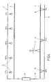
- FIG. 4 shows a large area luminaire 1 fastened to a ceiling (not shown), which essentially consist of lamps arranged side by side, here Fluorescent tubes 12 and a diffuser suspended below them in the form of a film 6 consists.
- the distance between the light sources 12 and their distance from the Diffusers are chosen so that by overlaying the individual illuminants 12 radiated brightness, a uniform illumination of the diffuser 6 is effected, without individual bulbs undesirably emerging.
- a Control / data line 18 includes the light sources 12 which can be influenced in terms of their brightness a central control unit 17 connected. This is the case with fluorescent tubes Dimming generally via electronic ballasts, which are not shown in FIG. 4 are drawn.
- the power supply to the light sources 12 is also not shown in FIG. 4 explicitly drawn.
- the control / data line 18 is optionally a point-to-point connection or bus executable, depending on the light sources used or Ballasts.
- the control unit 17 is also connected to sensors embedded in the floor, for example capacitive proximity switches. For aesthetic reasons, these can be hidden from viewer 2. Depending on how the sensors 15 work these, of course, also attached above the diffuser 6 or on the walls be attached. Via a further data line 19, connected as a point-to-point connection or as a bus, the signals from the sensors 15 to the central Control unit 17 transmitted.
- the position of person 2 is determined as follows: depending on the proximity of object 2, sensors 15 send a signal between 0 and 100%.
- sensors 15 send a signal between 0 and 100%.
- the central control unit 17 determines the from these values Presumed position of person 2, whereby instead of providing a sensor matrix one sensor line, two-dimensional position determinations are also possible.
- light sources 12 Brightness applied from left to right as follows: 31%, 100%, 100%. 30%, 5 %.
- FIGS. 1 to 3 Special applications and further details are shown in FIGS. 1 to 3 explained.
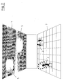
- FIG. 1 shows a large area luminaire 1 designed as a wall surface, behind which there is several invisible light sources, sensor elements and ballasts are located.
- the area of the existing people 2 is only in their immediate vicinity lighting is provided, which is characterized by the illuminated wall area 3 is, while existing in the end areas or in the intermediate area Light sources cannot be controlled.
- Figure 2 shows a similar arrangement, but it is a Large area light 4 acts, which is mounted on a ceiling and the one below illuminates the room. Only where people 2 are present individual islands of light 5, which are indicated by brightly lit circles, during the remaining area is not illuminated.
- the unrecognizable sensors can For example, be arranged behind a diffuser 6 or in the bottom 7.
- FIG. 3 shows a diffuser 10, for example a, in a sectional side view Translucent film in front of a lighting device 11 consisting of light sources 12, for example fluorescent tubes, and ballasts 13.
- the Ballasts 13 are mounted with the light sources 12 on a support plate 14 can in turn be attached to a wall or ceiling.
- a flat sensor 15 is arranged, with its Electric field 16 penetrates the diffuser 10 and the area in front of or below the diffuser 10 detected. In the event of a disorder caused by a person electromagnetic field 16, this is thus detected by the sensor 15, one Distance determination and the speed of the approaching person possible is.
- the control unit can use the necessary information is provided in order to control the individual Allow light sources 12.
- the control can, for example, be in a change but the color temperature preferably consists of a change in intensity.
Landscapes
- Engineering & Computer Science (AREA)
- Architecture (AREA)
- General Engineering & Computer Science (AREA)
- Physics & Mathematics (AREA)
- Electromagnetism (AREA)
- Civil Engineering (AREA)
- Structural Engineering (AREA)
- Human Computer Interaction (AREA)
- Circuit Arrangement For Electric Light Sources In General (AREA)
- Non-Portable Lighting Devices Or Systems Thereof (AREA)
- Geophysics And Detection Of Objects (AREA)
Applications Claiming Priority (4)
| Application Number | Priority Date | Filing Date | Title |
|---|---|---|---|
| DE10247071 | 2002-10-09 | ||
| DE10247071 | 2002-10-09 | ||
| DE10251731 | 2002-11-05 | ||
| DE10251731 | 2002-11-05 |
Publications (3)
| Publication Number | Publication Date |
|---|---|
| EP1408276A2 true EP1408276A2 (fr) | 2004-04-14 |
| EP1408276A3 EP1408276A3 (fr) | 2006-06-21 |
| EP1408276B1 EP1408276B1 (fr) | 2009-08-05 |
Family
ID=32031489
Family Applications (1)
| Application Number | Title | Priority Date | Filing Date |
|---|---|---|---|
| EP03020936A Expired - Lifetime EP1408276B1 (fr) | 2002-10-09 | 2003-09-16 | Système d'éclairage utilisant des détecteurs |
Country Status (3)
| Country | Link |
|---|---|
| EP (1) | EP1408276B1 (fr) |
| AT (1) | ATE438825T1 (fr) |
| DE (2) | DE10343062A1 (fr) |
Cited By (28)
| Publication number | Priority date | Publication date | Assignee | Title |
|---|---|---|---|---|
| WO2008012721A3 (fr) * | 2006-07-26 | 2008-03-27 | Koninkl Philips Electronics Nv | Dispositif de support de lampe et système comprenant des dispositifs de support de lampe et une unité de commande sans fil |
| AT504397B1 (de) * | 2006-10-27 | 2009-03-15 | Bartenbach Christian | Aussenleuchtenanordnung |
| WO2009144657A1 (fr) * | 2008-05-29 | 2009-12-03 | Philips Intellectual Property & Standards Gmbh | Informations de commande pour commander un système d'éclairage |
| EP2160078A1 (fr) | 2008-08-26 | 2010-03-03 | Panasonic Electric Works Co., Ltd. | Système d'illumination |
| WO2010010493A3 (fr) * | 2008-07-21 | 2010-03-18 | Koninklijke Philips Electronics N.V. | Procédé de réglage d’un luminaire et luminaire à appliquer au procédé |
| EP2180248A1 (fr) * | 2008-10-27 | 2010-04-28 | Panasonic Electric Works Co., Ltd. | Appareil d'éclairage |
| EP2271184A1 (fr) * | 2009-07-01 | 2011-01-05 | Osram Gesellschaft mit beschränkter Haftung | Procédé d'éclairage et système, par exemple pour éclairer les rues et les routes |
| WO2011023184A1 (fr) * | 2009-08-31 | 2011-03-03 | Hülsta-Werke Hüls Gmbh & Co. Kg | Meuble à commande lumineuse |
| WO2011046464A1 (fr) * | 2009-10-12 | 2011-04-21 | Beloglovskiy Sergey Yakovlevich | Procédé d'organisation d'éclairage artificiel économe et dispositif intellectuel pour sa mise en oeuvre (et variantes) |
| EP2364068A1 (fr) * | 2010-02-26 | 2011-09-07 | Sanyo Electric Co., Ltd. | Appareil de contrôle d'éclairage |
| WO2011151796A1 (fr) * | 2010-06-03 | 2011-12-08 | Koninklijke Philips Electronics N.V. | Système et procédé permettant de commander l'éclairage |
| CN102448230A (zh) * | 2011-10-24 | 2012-05-09 | 丽水市海威光控科技有限公司 | 一种用于公路隧道的红外车辆跟踪led照明调光方法 |
| EP2538757A1 (fr) * | 2011-06-22 | 2012-12-26 | Panasonic Corporation | Dispositif d'éclairage |
| US8427076B2 (en) | 2007-06-29 | 2013-04-23 | Carmanah Technologies Corp. | Intelligent area lighting system |
| WO2013084158A1 (fr) | 2011-12-08 | 2013-06-13 | Koninklijke Philips Electronics N.V. | Appareil d'éclairage |
| AT509035B1 (de) * | 2009-11-11 | 2013-07-15 | Illumination Network Systems Gmbh | Beleuchtungsvorrichtung und beleuchtungssystem |
| WO2013152258A1 (fr) * | 2012-04-05 | 2013-10-10 | Rethink Robotics, Inc. | Indication visuelle de suivi de cible |
| WO2013121342A3 (fr) * | 2012-02-16 | 2013-12-19 | Koninklijke Philips N.V. | Appareil et procédés de configuration d'éclairage utilisant des capteurs de distance |
| DE102013212671A1 (de) | 2013-06-28 | 2014-12-31 | Itz Innovations- Und Technologiezentrum Gmbh | Variables Decken- bzw. Wandleuchtensystem |
| CN104676441A (zh) * | 2015-01-14 | 2015-06-03 | 郑见伟 | 一种实现虚拟智能地毯的方法 |
| WO2016191560A1 (fr) * | 2015-05-26 | 2016-12-01 | Idd Aerospace Corporation | Éclairage réglable dans un aéronef basé sur l'emplacement d'un objet mobile |
| AT15517U1 (de) * | 2014-08-26 | 2017-11-15 | Tridonic Gmbh & Co Kg | System zur ortsaufgelösten Beleuchtungssteuerung |
| US9860127B2 (en) | 2011-06-09 | 2018-01-02 | Philips Lighting Holding B.V. | Method for configuring a network |
| WO2018048528A1 (fr) * | 2016-09-08 | 2018-03-15 | Osram Sylvania Inc. | Éclairage d'occupation doux dans l'espace et dans le temps |
| AT16240U1 (de) * | 2016-02-05 | 2019-05-15 | Zumtobel Lighting Gmbh | Lichtbandsystem mit mehreren ansteuerbaren Lichtbandmodulen |
| EP3543121A1 (fr) * | 2018-03-20 | 2019-09-25 | Rockwell Collins, Inc. | Système d'éclairage suivant les objets |
| CN115316046A (zh) * | 2020-03-27 | 2022-11-08 | 三菱电机株式会社 | 照明管理装置、照明管理系统、学习装置以及推理装置 |
| CN119012463A (zh) * | 2024-10-21 | 2024-11-22 | 宁波能亮光电科技有限公司 | 一种感应灯联动控制系统 |
Families Citing this family (13)
| Publication number | Priority date | Publication date | Assignee | Title |
|---|---|---|---|---|
| JP4252938B2 (ja) | 2004-07-07 | 2009-04-08 | 株式会社デンソー | 車両の車室照明装置 |
| DE102004058055B3 (de) * | 2004-12-01 | 2006-03-16 | Abb Research Ltd. | Bewegungsmeldersystem mit mehreren Bewegungsmeldern |
| DE102006024512A1 (de) * | 2006-05-23 | 2007-11-29 | Judith Gabel | System zur Regelung und Steuerung von Lichtquellen und Beleuchtungseinrichtungen |
| DE102006057755A1 (de) * | 2006-12-07 | 2008-06-12 | Zumtobel Lighting Gmbh | Steuerbare Beleuchtungsanlage |
| DE102007035412A1 (de) * | 2007-07-26 | 2009-01-29 | Igs Development Gmbh | Dimmervorrichtung zur Steuerung der Leistungsaufnahme von Verbrauchern |
| DE102009024412B4 (de) | 2009-02-05 | 2021-12-09 | Osram Gmbh | Verfahren zum Betreiben eines Beleuchtungssystems und Computerprogramm |
| RU2543937C2 (ru) * | 2009-06-03 | 2015-03-10 | Конинклейке Филипс Электроникс Н.В. | Оценка положений громкоговорителей |
| DE102011012336A1 (de) * | 2011-02-24 | 2012-08-30 | Dula-Werke Dustmann & Co. Gmbh | Verfahren zur automatisierten Einstellung von Umgebungsparametern an Präsentationsflächen sowie Vorrichtung hierzu |
| JP5899501B2 (ja) * | 2012-06-27 | 2016-04-06 | パナソニックIpマネジメント株式会社 | 照明システム |
| DE102014004434B4 (de) * | 2014-03-28 | 2025-01-02 | Trilux Gmbh & Co. Kg | Beleuchtungssystem und Betriebsverfahren mit einer Mehrzahl von gekoppelten Leuchten und Bewegungsmeldern |
| DE102015114842A1 (de) * | 2015-09-04 | 2017-03-09 | Lupyled Gmbh | Folienartige Beleuchtungseinrichtung |
| DE102021118773A1 (de) * | 2021-07-20 | 2023-01-26 | Reichhardt Gmbh Steuerungstechnik | Beleuchtungssystem mit mehreren Leuchten |
| WO2024002796A1 (fr) * | 2022-06-27 | 2024-01-04 | Signify Holding B.V. | Procédé et système d'éclairage à commande de couleur adaptative |
Family Cites Families (8)
| Publication number | Priority date | Publication date | Assignee | Title |
|---|---|---|---|---|
| JPS5384372A (en) * | 1976-12-30 | 1978-07-25 | Matsushita Electric Works Ltd | Lighting device in combination of warning device and power line conveyance |
| JPH07263151A (ja) * | 1994-03-28 | 1995-10-13 | Matsushita Electric Works Ltd | 照明制御装置 |
| AU701880B2 (en) * | 1995-03-21 | 1999-02-11 | Lutron Electronics Co., Inc. | Improved system for individual and remote control of spaced lighting fixtures |
| US6079862A (en) * | 1996-02-22 | 2000-06-27 | Matsushita Electric Works, Ltd. | Automatic tracking lighting equipment, lighting controller and tracking apparatus |
| DE19645184A1 (de) * | 1996-11-02 | 1998-05-07 | Abb Patent Gmbh | Schalteinrichtung für eine Treppenhausbeleuchtung |
| US5803589A (en) * | 1997-01-10 | 1998-09-08 | Lee; Chi-Hsiang | Ceiling lighting fixture |
| CA2277645A1 (fr) * | 1999-07-15 | 2001-01-15 | Quality Craft Importers Ltd. | Detecteur de mouvement integre a un plafonnier encastre |
| SE521058C3 (sv) * | 2002-05-21 | 2003-10-22 | Cellux Ab | Anordning för att tända och släcka belysningar vid väg, spår eller annan sträckning |
-
2003
- 2003-09-16 EP EP03020936A patent/EP1408276B1/fr not_active Expired - Lifetime
- 2003-09-16 DE DE2003143062 patent/DE10343062A1/de not_active Withdrawn
- 2003-09-16 AT AT03020936T patent/ATE438825T1/de active
- 2003-09-16 DE DE50311772T patent/DE50311772D1/de not_active Expired - Lifetime
Cited By (51)
| Publication number | Priority date | Publication date | Assignee | Title |
|---|---|---|---|---|
| WO2008012721A3 (fr) * | 2006-07-26 | 2008-03-27 | Koninkl Philips Electronics Nv | Dispositif de support de lampe et système comprenant des dispositifs de support de lampe et une unité de commande sans fil |
| US8497635B2 (en) | 2006-07-26 | 2013-07-30 | Koninklijke Philips N.V. | Lamp-holding device and system comprising lamp-holding devices and wireless controller |
| CN101496450B (zh) * | 2006-07-26 | 2013-12-04 | 皇家飞利浦电子股份有限公司 | 灯支撑设备和包括多个灯支撑设备与无线控制器的系统 |
| AT504397B1 (de) * | 2006-10-27 | 2009-03-15 | Bartenbach Christian | Aussenleuchtenanordnung |
| US8427076B2 (en) | 2007-06-29 | 2013-04-23 | Carmanah Technologies Corp. | Intelligent area lighting system |
| WO2009144657A1 (fr) * | 2008-05-29 | 2009-12-03 | Philips Intellectual Property & Standards Gmbh | Informations de commande pour commander un système d'éclairage |
| WO2010010493A3 (fr) * | 2008-07-21 | 2010-03-18 | Koninklijke Philips Electronics N.V. | Procédé de réglage d’un luminaire et luminaire à appliquer au procédé |
| US8791649B2 (en) | 2008-07-21 | 2014-07-29 | Koninklijke Philips N.V. | Method of setting up a luminaire and luminaire to apply the method |
| EP2160078A1 (fr) | 2008-08-26 | 2010-03-03 | Panasonic Electric Works Co., Ltd. | Système d'illumination |
| US8058819B2 (en) | 2008-08-26 | 2011-11-15 | Panasonic Electric Works Co., Ltd. | Illumination system |
| CN101662866B (zh) * | 2008-08-26 | 2013-06-19 | 松下电器产业株式会社 | 照明系统 |
| EP2180248A1 (fr) * | 2008-10-27 | 2010-04-28 | Panasonic Electric Works Co., Ltd. | Appareil d'éclairage |
| CN101725855B (zh) * | 2008-10-27 | 2012-01-11 | 松下电工株式会社 | 照明装置 |
| US8172423B2 (en) | 2008-10-27 | 2012-05-08 | Panasonic Electric Works Co., Ltd. | Illumination apparatus |
| EP2271184A1 (fr) * | 2009-07-01 | 2011-01-05 | Osram Gesellschaft mit beschränkter Haftung | Procédé d'éclairage et système, par exemple pour éclairer les rues et les routes |
| WO2011023184A1 (fr) * | 2009-08-31 | 2011-03-03 | Hülsta-Werke Hüls Gmbh & Co. Kg | Meuble à commande lumineuse |
| WO2011046464A1 (fr) * | 2009-10-12 | 2011-04-21 | Beloglovskiy Sergey Yakovlevich | Procédé d'organisation d'éclairage artificiel économe et dispositif intellectuel pour sa mise en oeuvre (et variantes) |
| AT509035B1 (de) * | 2009-11-11 | 2013-07-15 | Illumination Network Systems Gmbh | Beleuchtungsvorrichtung und beleuchtungssystem |
| US8456102B2 (en) | 2010-02-26 | 2013-06-04 | Sanyo Electric Co., Ltd. | Illumination control apparatus |
| EP2364068A1 (fr) * | 2010-02-26 | 2011-09-07 | Sanyo Electric Co., Ltd. | Appareil de contrôle d'éclairage |
| WO2011151796A1 (fr) * | 2010-06-03 | 2011-12-08 | Koninklijke Philips Electronics N.V. | Système et procédé permettant de commander l'éclairage |
| US9860127B2 (en) | 2011-06-09 | 2018-01-02 | Philips Lighting Holding B.V. | Method for configuring a network |
| EP2538757A1 (fr) * | 2011-06-22 | 2012-12-26 | Panasonic Corporation | Dispositif d'éclairage |
| US8779667B2 (en) | 2011-06-22 | 2014-07-15 | Panasonic Corporation | Illumination apparatus |
| CN102448230A (zh) * | 2011-10-24 | 2012-05-09 | 丽水市海威光控科技有限公司 | 一种用于公路隧道的红外车辆跟踪led照明调光方法 |
| CN102448230B (zh) * | 2011-10-24 | 2013-09-18 | 丽水市海威光控科技有限公司 | 一种用于公路隧道的红外车辆跟踪led照明调光方法 |
| WO2013084158A1 (fr) | 2011-12-08 | 2013-06-13 | Koninklijke Philips Electronics N.V. | Appareil d'éclairage |
| US9220147B2 (en) | 2011-12-08 | 2015-12-22 | Koninklijke Philips N.V. | Luminaire with a sensor that varies its activation in response to the presence or absence of objects |
| WO2013121342A3 (fr) * | 2012-02-16 | 2013-12-19 | Koninklijke Philips N.V. | Appareil et procédés de configuration d'éclairage utilisant des capteurs de distance |
| RU2623491C2 (ru) * | 2012-02-16 | 2017-06-27 | Филипс Лайтинг Холдинг Б.В. | Устройство и способы конфигурации освещения с использованием датчиков расстояния |
| US9936555B2 (en) * | 2012-02-16 | 2018-04-03 | Philips Lighting Holding B.V. | Lighting configuration apparatus and methods utilizing distance sensors |
| CN104115566A (zh) * | 2012-02-16 | 2014-10-22 | 皇家飞利浦有限公司 | 利用距离传感器的照明配置装置和方法 |
| CN104115566B (zh) * | 2012-02-16 | 2016-08-24 | 皇家飞利浦有限公司 | 利用距离传感器的照明配置装置和方法 |
| US9578708B2 (en) | 2012-02-16 | 2017-02-21 | Philips Lighting Holding B.V. | Lighting configuration apparatus and methods utilizing distance sensors |
| CN104349874A (zh) * | 2012-04-05 | 2015-02-11 | 睿信科机器人有限公司 | 目标跟踪的视觉指示 |
| US9283677B2 (en) | 2012-04-05 | 2016-03-15 | Rethink Robotics, Inc. | Visual indication of target tracking |
| WO2013152258A1 (fr) * | 2012-04-05 | 2013-10-10 | Rethink Robotics, Inc. | Indication visuelle de suivi de cible |
| DE102013212671B4 (de) | 2013-06-28 | 2018-07-19 | Itz Innovations- Und Technologiezentrum Gmbh | Variables Decken- bzw. Wandleuchtensystem sowie Grundplatte und Lichtmodul hierfür |
| DE102013212671A1 (de) | 2013-06-28 | 2014-12-31 | Itz Innovations- Und Technologiezentrum Gmbh | Variables Decken- bzw. Wandleuchtensystem |
| AT15517U1 (de) * | 2014-08-26 | 2017-11-15 | Tridonic Gmbh & Co Kg | System zur ortsaufgelösten Beleuchtungssteuerung |
| CN104676441B (zh) * | 2015-01-14 | 2017-08-01 | 郑见伟 | 一种实现虚拟智能地毯的方法 |
| CN104676441A (zh) * | 2015-01-14 | 2015-06-03 | 郑见伟 | 一种实现虚拟智能地毯的方法 |
| US10129954B2 (en) | 2015-05-26 | 2018-11-13 | Idd Aerospace Corporation | Adjustable lighting in an aircraft based on location of movable object |
| WO2016191560A1 (fr) * | 2015-05-26 | 2016-12-01 | Idd Aerospace Corporation | Éclairage réglable dans un aéronef basé sur l'emplacement d'un objet mobile |
| AT16240U1 (de) * | 2016-02-05 | 2019-05-15 | Zumtobel Lighting Gmbh | Lichtbandsystem mit mehreren ansteuerbaren Lichtbandmodulen |
| WO2018048528A1 (fr) * | 2016-09-08 | 2018-03-15 | Osram Sylvania Inc. | Éclairage d'occupation doux dans l'espace et dans le temps |
| US9980349B2 (en) | 2016-09-08 | 2018-05-22 | Osram Sylvania Inc. | Spatially and temporally smooth occupancy lighting |
| EP3543121A1 (fr) * | 2018-03-20 | 2019-09-25 | Rockwell Collins, Inc. | Système d'éclairage suivant les objets |
| US10449895B2 (en) | 2018-03-20 | 2019-10-22 | Rockwell Collins, Inc. | Object tracking illumination system |
| CN115316046A (zh) * | 2020-03-27 | 2022-11-08 | 三菱电机株式会社 | 照明管理装置、照明管理系统、学习装置以及推理装置 |
| CN119012463A (zh) * | 2024-10-21 | 2024-11-22 | 宁波能亮光电科技有限公司 | 一种感应灯联动控制系统 |
Also Published As
| Publication number | Publication date |
|---|---|
| DE10343062A1 (de) | 2004-05-27 |
| EP1408276B1 (fr) | 2009-08-05 |
| ATE438825T1 (de) | 2009-08-15 |
| EP1408276A3 (fr) | 2006-06-21 |
| DE50311772D1 (de) | 2009-09-17 |
Similar Documents
| Publication | Publication Date | Title |
|---|---|---|
| EP1408276B1 (fr) | Système d'éclairage utilisant des détecteurs | |
| EP1366265B1 (fr) | Element de fenetre | |
| DE10231502A1 (de) | Fensterelement | |
| DE102004026730A1 (de) | Fläche mit elektrischen Verbrauchern, insbesondere Leuchtmitteln | |
| DE202006005427U1 (de) | Beleuchtungsvorrichtung | |
| EP2893775B1 (fr) | Luminaire | |
| EP1297280B1 (fr) | Element d'eclairage | |
| DE102016124257B4 (de) | Leuchte | |
| EP3013123B1 (fr) | Système d'éclairage et procédé de commande correspondant | |
| EP2838828B1 (fr) | Panneau transparent pouvant être éclairé pour un escalier roulant, un trottoir roulant ou une cabine d'ascenseur | |
| DE10359376A1 (de) | Beleuchtungsvorrichtung, insbesondere Therapieleuchte | |
| DE10056745B4 (de) | Leuchte mit farbigem Indirekt-Lichtanteil und Verfahren zu ihrer Steuerung | |
| EP1323976A2 (fr) | Dispositif d'éclairage | |
| DE202006005428U1 (de) | Beleuchtbare Fliese | |
| DE10220588A1 (de) | Leuchte zur Arbeitsplatzbeleuchtung | |
| DE202013010375U1 (de) | Beleuchtungsvorrichtung für ein Patientenzimmer und Beleuchtungssystem | |
| DE10064703B4 (de) | Sandwichartiges Plattenelement | |
| DE102013225889A1 (de) | Panelleuchte | |
| DE10163957A1 (de) | Elektronisches Vorschaltgerät | |
| EP4039135B1 (fr) | Dispositif miroir à mode lumière nocturne | |
| DE10256383A1 (de) | Transparente Fläche mit Fluoreszenzmitteln und Beleuchtungsvorrichtung mit einer derartigen Fläche | |
| DE202008000386U1 (de) | Sensitives Flächenelement | |
| WO2015144625A1 (fr) | Chambranle pour une ouverture de cloison ou de mur | |
| EP1437927A2 (fr) | Luminaire | |
| EP0651200B1 (fr) | Dispositif d'éclairage |
Legal Events
| Date | Code | Title | Description |
|---|---|---|---|
| PUAI | Public reference made under article 153(3) epc to a published international application that has entered the european phase |
Free format text: ORIGINAL CODE: 0009012 |
|
| AK | Designated contracting states |
Kind code of ref document: A2 Designated state(s): AT BE BG CH CY CZ DE DK EE ES FI FR GB GR HU IE IT LI LU MC NL PT RO SE SI SK TR |
|
| AX | Request for extension of the european patent |
Extension state: AL LT LV MK |
|
| PUAL | Search report despatched |
Free format text: ORIGINAL CODE: 0009013 |
|
| AK | Designated contracting states |
Kind code of ref document: A3 Designated state(s): AT BE BG CH CY CZ DE DK EE ES FI FR GB GR HU IE IT LI LU MC NL PT RO SE SI SK TR |
|
| AX | Request for extension of the european patent |
Extension state: AL LT LV MK |
|
| 17P | Request for examination filed |
Effective date: 20061122 |
|
| AKX | Designation fees paid |
Designated state(s): AT BE BG CH CY CZ DE DK EE ES FI FR GB GR HU IE IT LI LU MC NL PT RO SE SI SK TR |
|
| 17Q | First examination report despatched |
Effective date: 20070202 |
|
| GRAP | Despatch of communication of intention to grant a patent |
Free format text: ORIGINAL CODE: EPIDOSNIGR1 |
|
| GRAS | Grant fee paid |
Free format text: ORIGINAL CODE: EPIDOSNIGR3 |
|
| GRAA | (expected) grant |
Free format text: ORIGINAL CODE: 0009210 |
|
| AK | Designated contracting states |
Kind code of ref document: B1 Designated state(s): AT BE BG CH CY CZ DE DK EE ES FI FR GB GR HU IE IT LI LU MC NL PT RO SE SI SK TR |
|
| REG | Reference to a national code |
Ref country code: GB Ref legal event code: FG4D Free format text: NOT ENGLISH |
|
| REG | Reference to a national code |
Ref country code: CH Ref legal event code: EP |
|
| REG | Reference to a national code |
Ref country code: IE Ref legal event code: FG4D |
|
| REF | Corresponds to: |
Ref document number: 50311772 Country of ref document: DE Date of ref document: 20090917 Kind code of ref document: P |
|
| REG | Reference to a national code |
Ref country code: SE Ref legal event code: TRGR |
|
| PG25 | Lapsed in a contracting state [announced via postgrant information from national office to epo] |
Ref country code: ES Free format text: LAPSE BECAUSE OF FAILURE TO SUBMIT A TRANSLATION OF THE DESCRIPTION OR TO PAY THE FEE WITHIN THE PRESCRIBED TIME-LIMIT Effective date: 20091116 |
|
| PG25 | Lapsed in a contracting state [announced via postgrant information from national office to epo] |
Ref country code: SI Free format text: LAPSE BECAUSE OF FAILURE TO SUBMIT A TRANSLATION OF THE DESCRIPTION OR TO PAY THE FEE WITHIN THE PRESCRIBED TIME-LIMIT Effective date: 20090805 |
|
| REG | Reference to a national code |
Ref country code: IE Ref legal event code: FD4D |
|
| PG25 | Lapsed in a contracting state [announced via postgrant information from national office to epo] |
Ref country code: BG Free format text: LAPSE BECAUSE OF FAILURE TO SUBMIT A TRANSLATION OF THE DESCRIPTION OR TO PAY THE FEE WITHIN THE PRESCRIBED TIME-LIMIT Effective date: 20091105 Ref country code: PT Free format text: LAPSE BECAUSE OF FAILURE TO SUBMIT A TRANSLATION OF THE DESCRIPTION OR TO PAY THE FEE WITHIN THE PRESCRIBED TIME-LIMIT Effective date: 20091205 |
|
| PG25 | Lapsed in a contracting state [announced via postgrant information from national office to epo] |
Ref country code: DK Free format text: LAPSE BECAUSE OF FAILURE TO SUBMIT A TRANSLATION OF THE DESCRIPTION OR TO PAY THE FEE WITHIN THE PRESCRIBED TIME-LIMIT Effective date: 20090805 Ref country code: MC Free format text: LAPSE BECAUSE OF NON-PAYMENT OF DUE FEES Effective date: 20090930 Ref country code: EE Free format text: LAPSE BECAUSE OF FAILURE TO SUBMIT A TRANSLATION OF THE DESCRIPTION OR TO PAY THE FEE WITHIN THE PRESCRIBED TIME-LIMIT Effective date: 20090805 Ref country code: IE Free format text: LAPSE BECAUSE OF FAILURE TO SUBMIT A TRANSLATION OF THE DESCRIPTION OR TO PAY THE FEE WITHIN THE PRESCRIBED TIME-LIMIT Effective date: 20090805 Ref country code: CZ Free format text: LAPSE BECAUSE OF FAILURE TO SUBMIT A TRANSLATION OF THE DESCRIPTION OR TO PAY THE FEE WITHIN THE PRESCRIBED TIME-LIMIT Effective date: 20090805 Ref country code: RO Free format text: LAPSE BECAUSE OF FAILURE TO SUBMIT A TRANSLATION OF THE DESCRIPTION OR TO PAY THE FEE WITHIN THE PRESCRIBED TIME-LIMIT Effective date: 20090805 |
|
| PG25 | Lapsed in a contracting state [announced via postgrant information from national office to epo] |
Ref country code: SK Free format text: LAPSE BECAUSE OF FAILURE TO SUBMIT A TRANSLATION OF THE DESCRIPTION OR TO PAY THE FEE WITHIN THE PRESCRIBED TIME-LIMIT Effective date: 20090805 |
|
| PLBE | No opposition filed within time limit |
Free format text: ORIGINAL CODE: 0009261 |
|
| STAA | Information on the status of an ep patent application or granted ep patent |
Free format text: STATUS: NO OPPOSITION FILED WITHIN TIME LIMIT |
|
| 26N | No opposition filed |
Effective date: 20100507 |
|
| PG25 | Lapsed in a contracting state [announced via postgrant information from national office to epo] |
Ref country code: GR Free format text: LAPSE BECAUSE OF FAILURE TO SUBMIT A TRANSLATION OF THE DESCRIPTION OR TO PAY THE FEE WITHIN THE PRESCRIBED TIME-LIMIT Effective date: 20091106 |
|
| PGFP | Annual fee paid to national office [announced via postgrant information from national office to epo] |
Ref country code: CH Payment date: 20100913 Year of fee payment: 8 |
|
| PGFP | Annual fee paid to national office [announced via postgrant information from national office to epo] |
Ref country code: AT Payment date: 20100910 Year of fee payment: 8 Ref country code: FI Payment date: 20100917 Year of fee payment: 8 Ref country code: FR Payment date: 20100921 Year of fee payment: 8 Ref country code: LU Payment date: 20100914 Year of fee payment: 8 Ref country code: SE Payment date: 20100913 Year of fee payment: 8 |
|
| PGFP | Annual fee paid to national office [announced via postgrant information from national office to epo] |
Ref country code: GB Payment date: 20100923 Year of fee payment: 8 |
|
| PGFP | Annual fee paid to national office [announced via postgrant information from national office to epo] |
Ref country code: NL Payment date: 20100910 Year of fee payment: 8 |
|
| PGFP | Annual fee paid to national office [announced via postgrant information from national office to epo] |
Ref country code: BE Payment date: 20100910 Year of fee payment: 8 Ref country code: DE Payment date: 20101113 Year of fee payment: 8 |
|
| PG25 | Lapsed in a contracting state [announced via postgrant information from national office to epo] |
Ref country code: IT Free format text: LAPSE BECAUSE OF NON-PAYMENT OF DUE FEES Effective date: 20090916 |
|
| PG25 | Lapsed in a contracting state [announced via postgrant information from national office to epo] |
Ref country code: HU Free format text: LAPSE BECAUSE OF FAILURE TO SUBMIT A TRANSLATION OF THE DESCRIPTION OR TO PAY THE FEE WITHIN THE PRESCRIBED TIME-LIMIT Effective date: 20100206 |
|
| REG | Reference to a national code |
Ref country code: DE Ref legal event code: R082 Ref document number: 50311772 Country of ref document: DE Representative=s name: KOENIG SZYNKA TILMANN VON RENESSE, DE Ref country code: DE Ref legal event code: R082 Ref document number: 50311772 Country of ref document: DE Representative=s name: KOENIG, SZYNKA, TILMANN, VON RENESSE PATENTANW, DE Ref country code: DE Ref legal event code: R082 Ref document number: 50311772 Country of ref document: DE Representative=s name: KOENIG SZYNKA TILMANN VON RENESSE PATENTANWAEL, DE |
|
| PGFP | Annual fee paid to national office [announced via postgrant information from national office to epo] |
Ref country code: IT Payment date: 20100923 Year of fee payment: 8 |
|
| PGRI | Patent reinstated in contracting state [announced from national office to epo] |
Ref country code: IT Effective date: 20110616 |
|
| PG25 | Lapsed in a contracting state [announced via postgrant information from national office to epo] |
Ref country code: TR Free format text: LAPSE BECAUSE OF FAILURE TO SUBMIT A TRANSLATION OF THE DESCRIPTION OR TO PAY THE FEE WITHIN THE PRESCRIBED TIME-LIMIT Effective date: 20090805 |
|
| PG25 | Lapsed in a contracting state [announced via postgrant information from national office to epo] |
Ref country code: CY Free format text: LAPSE BECAUSE OF FAILURE TO SUBMIT A TRANSLATION OF THE DESCRIPTION OR TO PAY THE FEE WITHIN THE PRESCRIBED TIME-LIMIT Effective date: 20090805 |
|
| BERE | Be: lapsed |
Owner name: KLUTH, MANFRED Effective date: 20110930 |
|
| REG | Reference to a national code |
Ref country code: NL Ref legal event code: V1 Effective date: 20120401 |
|
| REG | Reference to a national code |
Ref country code: CH Ref legal event code: PL |
|
| GBPC | Gb: european patent ceased through non-payment of renewal fee |
Effective date: 20110916 |
|
| PG25 | Lapsed in a contracting state [announced via postgrant information from national office to epo] |
Ref country code: FI Free format text: LAPSE BECAUSE OF NON-PAYMENT OF DUE FEES Effective date: 20110916 Ref country code: IT Free format text: LAPSE BECAUSE OF NON-PAYMENT OF DUE FEES Effective date: 20110916 |
|
| REG | Reference to a national code |
Ref country code: FR Ref legal event code: ST Effective date: 20120531 |
|
| PG25 | Lapsed in a contracting state [announced via postgrant information from national office to epo] |
Ref country code: BE Free format text: LAPSE BECAUSE OF NON-PAYMENT OF DUE FEES Effective date: 20110930 |
|
| REG | Reference to a national code |
Ref country code: SE Ref legal event code: EUG |
|
| REG | Reference to a national code |
Ref country code: DE Ref legal event code: R119 Ref document number: 50311772 Country of ref document: DE Effective date: 20120403 |
|
| PG25 | Lapsed in a contracting state [announced via postgrant information from national office to epo] |
Ref country code: LI Free format text: LAPSE BECAUSE OF NON-PAYMENT OF DUE FEES Effective date: 20110930 Ref country code: CH Free format text: LAPSE BECAUSE OF NON-PAYMENT OF DUE FEES Effective date: 20110930 Ref country code: NL Free format text: LAPSE BECAUSE OF NON-PAYMENT OF DUE FEES Effective date: 20120401 Ref country code: DE Free format text: LAPSE BECAUSE OF NON-PAYMENT OF DUE FEES Effective date: 20120403 |
|
| PG25 | Lapsed in a contracting state [announced via postgrant information from national office to epo] |
Ref country code: FR Free format text: LAPSE BECAUSE OF NON-PAYMENT OF DUE FEES Effective date: 20110930 Ref country code: GB Free format text: LAPSE BECAUSE OF NON-PAYMENT OF DUE FEES Effective date: 20110916 |
|
| REG | Reference to a national code |
Ref country code: AT Ref legal event code: MM01 Ref document number: 438825 Country of ref document: AT Kind code of ref document: T Effective date: 20110916 |
|
| PG25 | Lapsed in a contracting state [announced via postgrant information from national office to epo] |
Ref country code: AT Free format text: LAPSE BECAUSE OF NON-PAYMENT OF DUE FEES Effective date: 20110916 |
|
| PG25 | Lapsed in a contracting state [announced via postgrant information from national office to epo] |
Ref country code: SE Free format text: LAPSE BECAUSE OF NON-PAYMENT OF DUE FEES Effective date: 20110917 |
|
| PG25 | Lapsed in a contracting state [announced via postgrant information from national office to epo] |
Ref country code: LU Free format text: LAPSE BECAUSE OF NON-PAYMENT OF DUE FEES Effective date: 20110916 |