EP1408295A2 - Procédé et dispositif pour réfrigérer des marchandises dans un conteneur de transport calorifugé utilisant un module de réfrigération - Google Patents
Procédé et dispositif pour réfrigérer des marchandises dans un conteneur de transport calorifugé utilisant un module de réfrigération Download PDFInfo
- Publication number
- EP1408295A2 EP1408295A2 EP03022711A EP03022711A EP1408295A2 EP 1408295 A2 EP1408295 A2 EP 1408295A2 EP 03022711 A EP03022711 A EP 03022711A EP 03022711 A EP03022711 A EP 03022711A EP 1408295 A2 EP1408295 A2 EP 1408295A2
- Authority
- EP
- European Patent Office
- Prior art keywords
- cooling
- dry ice
- cooling module
- grain
- screening
- Prior art date
- Legal status (The legal status is an assumption and is not a legal conclusion. Google has not performed a legal analysis and makes no representation as to the accuracy of the status listed.)
- Granted
Links
- 238000001816 cooling Methods 0.000 title claims abstract description 189
- 238000000034 method Methods 0.000 title claims abstract description 30
- CURLTUGMZLYLDI-UHFFFAOYSA-N Carbon dioxide Chemical compound O=C=O CURLTUGMZLYLDI-UHFFFAOYSA-N 0.000 claims abstract description 136
- 235000011089 carbon dioxide Nutrition 0.000 claims abstract description 114
- 239000002826 coolant Substances 0.000 claims abstract description 34
- 230000008569 process Effects 0.000 claims abstract description 6
- 239000008188 pellet Substances 0.000 claims description 34
- 238000012216 screening Methods 0.000 claims description 24
- 238000009826 distribution Methods 0.000 claims description 8
- 239000003795 chemical substances by application Substances 0.000 claims description 7
- 238000005469 granulation Methods 0.000 claims description 6
- 230000003179 granulation Effects 0.000 claims description 6
- 238000004519 manufacturing process Methods 0.000 claims description 5
- 230000001419 dependent effect Effects 0.000 claims description 4
- 239000002912 waste gas Substances 0.000 claims description 3
- 230000007797 corrosion Effects 0.000 claims description 2
- 238000005260 corrosion Methods 0.000 claims description 2
- 239000000463 material Substances 0.000 claims description 2
- 238000007873 sieving Methods 0.000 claims description 2
- 238000012549 training Methods 0.000 claims description 2
- 238000011144 upstream manufacturing Methods 0.000 claims description 2
- 238000005453 pelletization Methods 0.000 claims 1
- 239000008187 granular material Substances 0.000 abstract description 11
- 239000002245 particle Substances 0.000 abstract description 4
- 229910002092 carbon dioxide Inorganic materials 0.000 description 11
- 238000001704 evaporation Methods 0.000 description 11
- 230000008020 evaporation Effects 0.000 description 11
- 239000001569 carbon dioxide Substances 0.000 description 10
- 239000007789 gas Substances 0.000 description 7
- 238000009413 insulation Methods 0.000 description 7
- 239000003570 air Substances 0.000 description 6
- 239000007788 liquid Substances 0.000 description 6
- 230000000694 effects Effects 0.000 description 5
- 238000000859 sublimation Methods 0.000 description 5
- 230000008022 sublimation Effects 0.000 description 5
- IJGRMHOSHXDMSA-UHFFFAOYSA-N Atomic nitrogen Chemical compound N#N IJGRMHOSHXDMSA-UHFFFAOYSA-N 0.000 description 4
- 235000013305 food Nutrition 0.000 description 4
- 238000010521 absorption reaction Methods 0.000 description 3
- 230000033228 biological regulation Effects 0.000 description 3
- 230000007613 environmental effect Effects 0.000 description 3
- 239000000945 filler Substances 0.000 description 3
- 230000008014 freezing Effects 0.000 description 3
- 238000007710 freezing Methods 0.000 description 3
- 238000012544 monitoring process Methods 0.000 description 3
- 238000013461 design Methods 0.000 description 2
- 229910052757 nitrogen Inorganic materials 0.000 description 2
- 238000003825 pressing Methods 0.000 description 2
- 238000003860 storage Methods 0.000 description 2
- XLYOFNOQVPJJNP-UHFFFAOYSA-N water Substances O XLYOFNOQVPJJNP-UHFFFAOYSA-N 0.000 description 2
- 230000009471 action Effects 0.000 description 1
- 239000012080 ambient air Substances 0.000 description 1
- 230000008859 change Effects 0.000 description 1
- 238000006243 chemical reaction Methods 0.000 description 1
- 230000007423 decrease Effects 0.000 description 1
- 230000003247 decreasing effect Effects 0.000 description 1
- 238000005516 engineering process Methods 0.000 description 1
- 238000000605 extraction Methods 0.000 description 1
- 235000013611 frozen food Nutrition 0.000 description 1
- 230000005484 gravity Effects 0.000 description 1
- 235000015243 ice cream Nutrition 0.000 description 1
- 238000002347 injection Methods 0.000 description 1
- 239000007924 injection Substances 0.000 description 1
- 230000001788 irregular Effects 0.000 description 1
- 238000012423 maintenance Methods 0.000 description 1
- 235000013372 meat Nutrition 0.000 description 1
- 238000012856 packing Methods 0.000 description 1
- 230000002028 premature Effects 0.000 description 1
- 230000001105 regulatory effect Effects 0.000 description 1
- 238000005549 size reduction Methods 0.000 description 1
- 239000007787 solid Substances 0.000 description 1
- 239000000243 solution Substances 0.000 description 1
- 239000000126 substance Substances 0.000 description 1
- 238000005303 weighing Methods 0.000 description 1
Images

Classifications
-
- F—MECHANICAL ENGINEERING; LIGHTING; HEATING; WEAPONS; BLASTING
- F25—REFRIGERATION OR COOLING; COMBINED HEATING AND REFRIGERATION SYSTEMS; HEAT PUMP SYSTEMS; MANUFACTURE OR STORAGE OF ICE; LIQUEFACTION SOLIDIFICATION OF GASES
- F25D—REFRIGERATORS; COLD ROOMS; ICE-BOXES; COOLING OR FREEZING APPARATUS NOT OTHERWISE PROVIDED FOR
- F25D3/00—Devices using other cold materials; Devices using cold-storage bodies
- F25D3/12—Devices using other cold materials; Devices using cold-storage bodies using solidified gases, e.g. carbon-dioxide snow
- F25D3/125—Movable containers
-
- A—HUMAN NECESSITIES
- A23—FOODS OR FOODSTUFFS; TREATMENT THEREOF, NOT COVERED BY OTHER CLASSES
- A23B—PRESERVATION OF FOODS, FOODSTUFFS OR NON-ALCOHOLIC BEVERAGES; CHEMICAL RIPENING OF FRUIT OR VEGETABLES
- A23B2/00—Preservation of foods or foodstuffs, in general
- A23B2/80—Freezing; Subsequent thawing; Cooling
- A23B2/85—Freezing; Subsequent thawing; Cooling with addition of or treatment with chemicals
- A23B2/88—Freezing; Subsequent thawing; Cooling with addition of or treatment with chemicals with direct contact between the food and the chemical, e.g. liquid N2 at cryogenic temperature
-
- F—MECHANICAL ENGINEERING; LIGHTING; HEATING; WEAPONS; BLASTING
- F25—REFRIGERATION OR COOLING; COMBINED HEATING AND REFRIGERATION SYSTEMS; HEAT PUMP SYSTEMS; MANUFACTURE OR STORAGE OF ICE; LIQUEFACTION SOLIDIFICATION OF GASES
- F25D—REFRIGERATORS; COLD ROOMS; ICE-BOXES; COOLING OR FREEZING APPARATUS NOT OTHERWISE PROVIDED FOR
- F25D29/00—Arrangement or mounting of control or safety devices
- F25D29/001—Arrangement or mounting of control or safety devices for cryogenic fluid systems
Definitions
- the invention relates to a method for cooling goods in a heat-insulated Transport container (hereinafter briefly: container), one with a cooling module for the Contains dry ice in thermal contact with the loading area, the cooling module depending on a predetermined cooling capacity and cooling duration Coolant of various amounts and properties is supplied.
- the invention relates to a device for setting a predetermined Cooling capacity in a cooling module for the absorption of dry ice, comprising a Coolant supply from which the cooling module depending on the specified Cooling power is supplied with coolant via a coolant supply.
- thermally insulating wall thermally insulated
- Transport container used.
- the containers are usually additionally cooled to to be able to maintain a low internal temperature over a longer period of time.
- the temperatures are between 0 ° C and + 12 ° C frozen goods such as frozen foods and ice cream at temperatures between -18 ° C to -25 ° C.
- the equilibrium temperature that is due to the insulated container Setting cooling performance and heat input depends on the ambient temperature.
- a Cooling capacity designed in view of high temperatures in summer can be colder Outside temperatures lead to freezing damage to the refrigerated goods, and vice versa Design case for a low outside temperature, the upper temperature limit in the container slightly exceeded in summer. Therefore, the cooling of goods in particular requires particularly narrow tolerance range, for example for meat between 0 and 4 ° C is a complex cooling technology with a coordination of the cooling capacity to the Ambient temperature.
- temperature control is used for cost reasons usually waived.
- Dry ice in the form of blocks is often used for cooling. Adapting the cooling capacity using such carbon dioxide blocks to the respective requirement is problematic.
- the surface of an ice block is relatively small in relation to its mass ( ⁇ 1 cm 2 / g), which results in a cooling capacity that is too low for practical purposes.
- dry ice blocks quickly become covered with water ice, which is formed from the air humidity and which leads to a greatly reduced cooling capacity.
- the cooling capacity is much higher because the snow has a porous structure and, for example, 10kg of snow in practically used shells has an outer, i.e. - around the bed outside - surface of 120 dm 2 compared to two 5 kg blocks with a surface of only approx. 20dm 2 to have.
- the dry ice snow is filled into a container that is usually trough-shaped and whose insulation determines the cooling capacity, keeps moisture out and thus significantly improves the system.
- liquid nitrogen is used for cooling, the necessary container is insulated so well that any freezing moisture does not significant change in insulation can cause.
- Cooling modules are known for cooling the containers, which use cryogenic liquid or filled with snow-like carbon dioxide or cryogenic liquid nitrogen as cooling media become.
- a cooling module is described in DE-T 694 04 231, from which also a method and a device of the type mentioned are known.
- DE-T 694 04 231 describes a method for cooling goods in an insulated container proposed using dry ice snow. This is in the upper area of the Container provided a dry ice compartment. A dosed amount is placed in the dry ice compartment injected by pressurized liquid carbon dioxide, the dosage on climatic conditions is matched. This makes it possible to put in the dry ice compartment resulting amount of dry ice snow to vary and to the current Adapt ambient temperatures.
- the device used to fill the dry ice compartment consists of a tank for liquid carbon dioxide, which is connected to the dry ice compartment via a pressure line can be, and from a control unit with a timer, by means of which the injection duration of pressurized liquid carbon dioxide into the dry ice compartment.
- the cooling capacity can also be adjusted using dry ice snow problematic. While at the beginning a high one with large amounts of carbon dioxide snow Cooling performance can be achieved, this is after a short time by (water, ice and Snow covering from the ambient air and above all premature sublimation of dry ice highly limited. Furthermore, the cooling capacity and the cooling time can of course only be achieved with a selectable parameter cannot be set independently.
- DE 563 068 discloses dry ice or solid carbonic acid as Use coolant for cooling devices.
- the coolant is placed in a Upper part of a cooling device arranged, designed as a bottomless bottle and introduced with its bottle neck towards the refrigerator. A continuous charging and quantity control of the coolant is not possible.
- EP 06 40 295 B1 describes a device for cooling a food product with a Means for applying a cryogenic substance (carbon dioxide snow) to the in a Storage chamber brought food product.
- a cryogenic substance carbon dioxide snow
- DE 195 41 338 A1 shows a method and an apparatus for cooling Floor cover layers or coverings, in which a granulate of frozen particles, in particular from dry ice pellets, preferably flat on the goods to be cooled is applied. By temperature, the particle size and / or the applied The layer cooling capacity of the granulate can be adjusted. This specifically technical solution designed for cooling floor coverings or coverings but unsuitable for cooling goods in a container.
- the object of the invention is to provide a simple, alternative method that it using dry ice enables the cooling capacity and the cooling time independently to match each other within a container to the environmental conditions.
- the invention is based, an inexpensive and at the same time the task Maintenance and user-friendly device for cooling goods in one Provide containers that are characterized by a high level of operational reliability and a required cooling capacity and cooling time easily adjustable cooling generation distinguished, and in which room air monitoring and suction are dispensed with can.
- this task is based on the above Method according to the invention solved in that as a coolant in its specific Surface and quantity depending on the cooling capacity and the cooling time in advance set dry ice grain is fed to the cooling module and in the cooling module in one grain size dependent on the cooling capacity and cooling time is distributed and evaporated.
- the specific surface area is the ratio of the surface area of the dry ice grain and their mass.
- the evaporation rate of dry ice granules depends, among other things. of its specific surface.
- the evaporation rate is just another measure of the cooling performance. A larger surface area leads to a higher evaporation rate and thus to a higher rate Cooling capacity and vice versa.
- the size of the surface of dry ice grain is determined by the amount (mass) Dry ice and the size and size distribution of the dry ice grains certainly.
- the cooling capacity is essentially determined by the specific Surface and the cooling time is determined by the mass.
- the specific surface of the dry ice granulation is preferably carried out by Crushing dry ice pellets set. Dry ice pellets are coarse-grained particles with an average diameter in the range from 2 to 20 mm. This are obtained, for example, using commercially available dry ice pelletizers
- the average grain size of the dry ice grain can be reduced by crushing the dry ice pellets and thus adjust the specific surface of the grain in a wide range.
- a shredding device with an adjustable, controllable or adjustable, movable shredding tool for example a rotating one Knife, used.
- the average grain size of the dry ice grain - and thus its specific surface and cooling capacity - is determined, for example, by speed the movement of the shredding tool.
- the crushing of the dry ice pellets proves to be a simple, reproducible process that does not require much apparatus and energy expenditure is feasible.
- the dry ice grain can therefore the required cooling capacity of the container before Transport easily adapted to the current conditions become.
- pellets which are already of a suitable size without introducing any further pretreatment into the cooling module.
- the cooling module with different Grain sizes introduced dry ice grain in the cooling module by means of an as Sieve plate arrangement trained device in different heat insulated Module areas (e.g. side wall and floor area) distributed, whereby one to the required cooling capacity and cooling time adapted cooling is guaranteed.
- different heat insulated Module areas e.g. side wall and floor area
- Sublimation effects matched coolant into the cooling module and through a - likewise matched to the existing sublimation effects - distribution of the coolant in the cooling module can maintain a constant cooling capacity over the entire cooling period be guaranteed.
- the ambient temperature of the Containers recorded, the specific surface area of the dry ice grain in Dependence on the ambient temperature is set.
- the capture of the Ambient temperature takes place, for example, by a temperature sensor or by a computer-based query with a weather forecasting service.
- the determined Ambient temperature flows automatically or by manual entry in a control for setting the grain size of the dry ice grain. In the simplest case it is a regulation for the rotational speed of a comminution tool a shredding device.
- the amount of Dry ice grain metered in primarily determines the cooling time of the cooling module. However, it also affects the cooling capacity, since the size of the free surface also depends on the grain size. The amount of dry ice granulation is therefore at Determination of the cooling capacity and the specific surface to be set for it consider. The contribution of the amount of gromung to the overall cooling capacity depends again on the specific surface of the dry ice grain. The described mutual dependencies are in the simplest case when determining the specific surface of the dry ice grain to be set empirically and coordinated.
- waste gas arising in the production of the dry ice pellets is transferred re-liquefaction is fed back into the process. This procedure is sensible for cost reasons, especially with larger amounts of exhaust gas. Otherwise it can the exhaust gas can also be discharged outdoors.
- the technical task specified above is based on the device from the device of the type mentioned - solved according to the invention by that the coolant supply with a sieve with a distribution of the dry ice grain Sorting device equipped cooling module is connected.
- the coolant can be stored in a chopper in which the Dry ice pellets are crushed into dry ice granules and by means of a feeder be directly or indirectly connected to a heat-insulated cooling module.
- the device according to the invention comes without pressurized apparatus and lines out. Leakage problems or complex safety devices so there is no need.
- the device is easy to use and is characterized by high operational reliability.
- the device can also be a device for Production of dry ice pellets (pelletizers) and / or a container for holding the same, the dry ice pellets either leaving this The device can be crushed immediately to dry ice or first in the mentioned Container.
- the comminution device is preferably a container for holding Upstream of dry ice pellets.
- the size of the container should be such that the it contained a stagnant replenishment of pellets from one of them connected pelletizers can bridge. This is preferably a automatic control provided by a level controller. Alternatively it is possible to design the container for a batch filling, in which case the Pelletizer can be installed elsewhere and the pellets are delivered ready.
- the shredding device Shredding tool with adjustable shredding degree for dry ice pellets includes.
- the middle one can be Grain size of the dry ice grain and thus the specific surface of the grain in wide range precisely and reproducibly.
- This is preferably a Shredding device with an adjustable, movable shredding tool, for example a rotating knife.
- the average grain size of the Grain of dry ice - and thus its specific surface and cooling capacity - becomes set on the speed of movement of the shredding tool.
- the degree of comminution depending on the Ambient temperature is adjustable.
- the one determined by the temperature sensor Ambient temperature flows automatically or by manual entry in a control for setting the grain size of the dry ice grain. In the simplest case it is a regulation for the rotational speed of a Shredding tool of the shredding device.
- a particularly safe and precise filling of the cooling modules results when in the Feeder for dry ice granulation a dosing device for dry ice granulation is arranged.
- the amount of dry ice granules is determined by the dosing device Cooling module dosed in a controlled manner.
- the amount of dry ice pellet addition determined in primarily the cooling time, but it is also when determining the cooling capacity and the account for the specific surface to be set and vice versa, how this has already been explained above using the method according to the invention.
- the shredding device with the Temperature sensor for the environmental conditions is connected. This is one Control of the specific surface area of the dry ice grain that reaches the cooling module taking into account the ambient temperature is particularly easy to implement.
- the metering device is advantageously provided with a level sensor, by means of which the supply of dry ice grain is recorded in the metering device. at Dry ice gromung is required by the shredding device - and if necessary from a pelletizer - supplied later.
- the waste gas that arises during the production of the dry ice pellets can be obtained through a Pipeline either led quantitatively into the open or - for large quantities - via one Reliquefaction can be fed back into the process.
- the to separate the coolant into different grain size ranges in the The screening and sorting device used for the cooling module consists of at least one Screening / sorting means.
- the screening and sorting device preferably has up to four screening / sorting means.
- the mesh size (hole size) of each screening / sorting agent is 2 to 20 mm.
- screening / sorting means in the invention is any for screening and sorting in different inner areas of the cooling module spaced apart and a variety of holes, from a cold and corrosion resistant Material of different training and structure called existing means, with whose help is the coolant introduced into the cooling module due to its weight due to transporter vibrations or other forces in different ways Grain size ranges separated and the separate coolant components in all interior areas of the cooling module can be distributed.
- the grain size between the two Products is determined by the size of the sieve openings certainly.
- the sieve trays are preferably spaced apart from the side wall of the cooling module arranged so that between each sieve plate and the inner wall of the one as an additional Thermal insulation acting air gap is formed.
- the screening / sorting means are as absorbing the dry ice grain with the smaller grain size, with the inner wall of the Cooling module formed heat-conducting honeycomb structures, whereby the Cold release of the dry ice grain in the honeycomb structures increased significantly becomes
- the screening / sorting means of the screening and sorting device used in the cooling module are selected so that the heat absorption of the coolant by the variable The distance between the individual screens and the outer skin can be varied.
- the sieve / sorting agent with the maximum hole size is closest to the filling opening of the Cooling module and the screening / sorting agent with the smallest hole size directly above the Bottom of the cooling module arranged.
- the hole sizes (mesh size) of each sieve / sorting agent is again dependent on the grain size of the coolant introduced into the cooling module, the speed the grain size reduction and the required cooling capacity and cooling time.
- the cooling module according to the invention enables a controlled, i.e. adjustable and constant evaporation of the coolant and thus the different Required cooling of goods stored in a transport container.
- the thermal insulation of the cooling module is the adapted to the respective cooling conditions. This allows the previously used Disadvantages associated with initially high and carbon dioxide snow then rapidly decreasing cooling capacity can be avoided.
- the dimensions and Thermal conductivity of the module wall dependent cooling capacity of the cooling module can are kept almost constant during the entire cooling period.
- An irregular pellet weighing 1 g has a surface area of approx. 6 cm 2 or a specific surface area of 6 cm 2 / g. 1 kg of these pellets evaporates (depending on the distribution) in about 2 hours.
- the cooling capacity is about 300 kJ / h.
- the specific surface area for a dry ice block is less than 1 cm 2 / g.
- a cube-shaped block of 1 kg weight ie 640 kJ cooling energy
- the energy absorption and thus the release of cold occurs only through evaporation on the surface. It evaporates in about a day. Its cooling capacity is therefore 640 kJ / 24h or 27 kJ / h.
- Table 1 shows the relationship between the grain size of the dry ice grain 6 (referred to as flakes, granules, nuggets) and the cooling capacity. The values are approximate and are based on a bulk of 1 kg. flakes (F) granules (G) nuggets (N) dimension diameter 15 15 15 mm length 1 5 20 mm Dimensions 0.177 0.883 3,533 G surface 4.00 5.89 12.95 Cm 2 Specific surface 22.7 6.7 3.7 Cm 2 / g evaporation 500 200 100 G / h Cooling capacity 0.085 0.034 0,017 KWh / kg
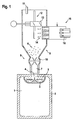
- the container 1 shown in FIG. 1 has a thermally insulating wall 2 Mistake.
- a cooling module 3 is arranged inside the container 1.
- the cooling module 3 has the shape of a shell which communicates with a filling opening 4 of the container 1 stands and has a gas opening in the interior of the container.
- the cooling module 3 which is equipped with two sieve trays 5, is provided with dry ice grain 6 filled.
- a filler neck 7 of a metering device 8 projects into the filling opening 4
- Dosing device 8 comprises a funnel-shaped container 9 in addition to the filler neck 7 the outlet of which a metering instrument 10 is arranged and a level sensor 11.
- the dosing device 8 is loaded with dry ice grain 6. This is within the Container 9 and above the metering 10 a chopper 12 with a rotating knife 13 arranged, the continuous dry ice pellets 14 and supplied be chopped by the rotating knife 13 to the dry ice grain 6.
- the dry ice pellets 14 are produced and fed via a pelletizer 15, which comprises a pressing device 16, which at the height of the rotating knife 13 in the Side wall of the container 9 is mounted.
- the press device 16 becomes carbon dioxide snow fed, which compacted therein and then via a press nozzle in the form of Dry ice pellets 14 transported into the interior of the container 9 and from there rotating knife 13 to a preset average grain size of the dry ice grain 6 is crushed.
- the pelletizer 15 supplies pellets 14 as soon as the stock decreases.
- the dry ice pellets 14 are sized by means of the chopper 12 crushed to a desired surface per kg of pellets and thus to the desired evaporation rate or cooling capacity, which leads to the respective Requirements is needed. E.g .: small pellets in midsummer, large pellets in lower outside temperatures.
- the metering instrument 10 conveys the dry ice grain 6 over the filler neck 7 and through a filling opening 4 into the cooling module 3 of the sieve plates 5 Container 1.
- Figure 2 shows two arranged within the container 1 in the manner described above Cooling modules 3 whose preferred embodiment can be seen in FIG. 3.
- the sieve plate 17 arranged in the cooling module 3 above the sieve plate 18 is spaced from the module side wall.
- This special arrangement of the sieve plate 17 in the cooling module 3 is between the Sieve bottom 17 and the inner wall of the cooling module 3 as additional heat insulation acting air gap.
- the sieve plate 18 arranged in the bottom area of the cooling module 3 is thermally connected to the side wall of the cooling module 3.
- the dry ice grain introduced into the cooling module 3 with a different grain size 19, 20 is in through the sieve plate 17, 18 depending on their grain size the cooling module 3 with the largest possible specific surface area distributed in such a way that an optimal evaporation of the coolant and thus the respective Cooling according to requirements by means of the cooling module 3 in the container 1 is guaranteed.
- the one grain size falls smaller than the respective mesh size of the bottom sieve 17, 18, partial amount (sieve passage) of dry ice grain 19.20 through Gravity and due to the transport-related vibrations caused by the Openings of the sieve bottom 17, 18 on the bottom wall of the cooling module 3 and evaporated there - as well as the partial quantity (sieve residue) of the sieve bottom 17, 18 left-over dry ice grain 19.20 - due to the effect of ambient heat.
- the sieve bottom 18 can, for example, also be one with the side wall of the cooling module 3 thermally connected honeycomb structure in the bottom area of the cooling module 3 be trained.
- the evaporation of the coolant takes place the faster, the less the coolant from the Environment is isolated, so the closer the coolant in the inner wall area of the cooling module 3rd is distributed.
Landscapes
- Engineering & Computer Science (AREA)
- Chemical & Material Sciences (AREA)
- Combustion & Propulsion (AREA)
- General Engineering & Computer Science (AREA)
- Life Sciences & Earth Sciences (AREA)
- Thermal Sciences (AREA)
- Mechanical Engineering (AREA)
- Physics & Mathematics (AREA)
- Zoology (AREA)
- Chemical Kinetics & Catalysis (AREA)
- Polymers & Plastics (AREA)
- Food Science & Technology (AREA)
- Wood Science & Technology (AREA)
- Carbon And Carbon Compounds (AREA)
- Devices That Are Associated With Refrigeration Equipment (AREA)
Applications Claiming Priority (2)
| Application Number | Priority Date | Filing Date | Title |
|---|---|---|---|
| DE10247489A DE10247489A1 (de) | 2002-10-11 | 2002-10-11 | Verfahren und Vorrichtung zum Kühlen von Waren in einem wärmeisolierten Transportbehälter unter Einsatz eines Kühlmoduls |
| DE10247489 | 2002-10-11 |
Publications (3)
| Publication Number | Publication Date |
|---|---|
| EP1408295A2 true EP1408295A2 (fr) | 2004-04-14 |
| EP1408295A3 EP1408295A3 (fr) | 2005-05-25 |
| EP1408295B1 EP1408295B1 (fr) | 2009-12-16 |
Family
ID=32010439
Family Applications (1)
| Application Number | Title | Priority Date | Filing Date |
|---|---|---|---|
| EP03022711A Expired - Lifetime EP1408295B1 (fr) | 2002-10-11 | 2003-10-09 | Procédé et dispositif pour réfrigérer des marchandises dans un conteneur de transport calorifugé utilisant un module de réfrigération |
Country Status (3)
| Country | Link |
|---|---|
| EP (1) | EP1408295B1 (fr) |
| AT (1) | ATE452318T1 (fr) |
| DE (2) | DE10247489A1 (fr) |
Cited By (5)
| Publication number | Priority date | Publication date | Assignee | Title |
|---|---|---|---|---|
| EP2604129A1 (fr) * | 2011-12-13 | 2013-06-19 | Linde Aktiengesellschaft | Procédé et dispositif destinés au maintien de la température |
| EP2873937A1 (fr) | 2013-11-13 | 2015-05-20 | ACP Belgium N.V. | Système d'entrepôt pour le stockage et le transport de produits à basse température |
| WO2017176572A1 (fr) * | 2016-04-04 | 2017-10-12 | Linde Aktiengesellschaft | Réfrigération pour cabas de distribution de provisions |
| CN112722531A (zh) * | 2020-12-24 | 2021-04-30 | 苏州浩宇南天信息科技有限公司 | 一种医疗药品运输用低温存储装置及其使用方法 |
| CN119898637A (zh) * | 2024-12-12 | 2025-04-29 | 广州市华达石化有限公司 | 一种基于三维模型的安全加料方法以及电子设备 |
Families Citing this family (2)
| Publication number | Priority date | Publication date | Assignee | Title |
|---|---|---|---|---|
| NO335251B1 (no) * | 2011-03-29 | 2014-10-27 | Trosterud Mekaniske Verksted As | Fremgangsmåte og anordning for distribusjon av tørrissnø |
| EP3141847A1 (fr) * | 2015-09-10 | 2017-03-15 | REWE Digital GmbH | Conteneur de transport pour produit congelés et/ou réfrigérés et procédé et dispositif de préparation à l'utilisation d'un récipient de transport |
Citations (4)
| Publication number | Priority date | Publication date | Assignee | Title |
|---|---|---|---|---|
| DE563068C (de) | 1931-04-01 | 1932-11-01 | G H Walb & Co | Kuehlschraenke oder Kuehlraeume fuer Trockeneis, wie z. B. feste Kohlensaeure, die in einem in der Isoliermasse des Oberteiles des Kuehlschrankes gelagerten Gefaess untergebracht ist |
| DE19541338A1 (de) | 1995-11-06 | 1997-05-07 | Linde Ag | Verfahren und Vorrichtung zum Kühlen von Bodendeckschichten oder -belägen |
| DE69404231T2 (de) | 1993-06-23 | 1997-12-18 | Carboxyque Francaise | Verfahren zur Konservierung von Waren bei niedrigen Temperaturen in einem isolierten Gehäuse, Vorrichtung zur Durchführung des Verfahrens, isoliertes Gehäuse und Behälter für solch ein Gehäuse |
| EP0640295B1 (fr) | 1993-08-30 | 2000-05-03 | The Boc Group, Inc. | Procédé et appareil pour réfrigérer des produits alimentaires |
Family Cites Families (5)
| Publication number | Priority date | Publication date | Assignee | Title |
|---|---|---|---|---|
| GB609432A (en) * | 1946-03-14 | 1948-09-30 | Frank George Brown | Improvements in or relating to apparatus employing solid carbon dioxide as a refrigerant |
| FR2565336B1 (fr) * | 1984-06-01 | 1987-01-09 | Keller Jean Paul | Machine de production de neige carbonique |
| ZW7192A1 (en) * | 1991-06-28 | 1992-08-08 | African Oxygen Ltd | A method and means for providing refrigeration |
| US6151913A (en) * | 1999-04-23 | 2000-11-28 | Praxair Technology, Inc. | Method and apparatus for agglomerating fine snow particles |
| DE10129217B4 (de) * | 2001-06-19 | 2006-07-06 | Air Liquide Deutschland Gmbh | Verfahren zum Kühlen von Waren in einem Isolierbehälter unter Einsatz eines Kühlmoduls |
-
2002
- 2002-10-11 DE DE10247489A patent/DE10247489A1/de not_active Withdrawn
-
2003
- 2003-10-09 AT AT03022711T patent/ATE452318T1/de active
- 2003-10-09 DE DE50312233T patent/DE50312233D1/de not_active Expired - Lifetime
- 2003-10-09 EP EP03022711A patent/EP1408295B1/fr not_active Expired - Lifetime
Patent Citations (4)
| Publication number | Priority date | Publication date | Assignee | Title |
|---|---|---|---|---|
| DE563068C (de) | 1931-04-01 | 1932-11-01 | G H Walb & Co | Kuehlschraenke oder Kuehlraeume fuer Trockeneis, wie z. B. feste Kohlensaeure, die in einem in der Isoliermasse des Oberteiles des Kuehlschrankes gelagerten Gefaess untergebracht ist |
| DE69404231T2 (de) | 1993-06-23 | 1997-12-18 | Carboxyque Francaise | Verfahren zur Konservierung von Waren bei niedrigen Temperaturen in einem isolierten Gehäuse, Vorrichtung zur Durchführung des Verfahrens, isoliertes Gehäuse und Behälter für solch ein Gehäuse |
| EP0640295B1 (fr) | 1993-08-30 | 2000-05-03 | The Boc Group, Inc. | Procédé et appareil pour réfrigérer des produits alimentaires |
| DE19541338A1 (de) | 1995-11-06 | 1997-05-07 | Linde Ag | Verfahren und Vorrichtung zum Kühlen von Bodendeckschichten oder -belägen |
Cited By (5)
| Publication number | Priority date | Publication date | Assignee | Title |
|---|---|---|---|---|
| EP2604129A1 (fr) * | 2011-12-13 | 2013-06-19 | Linde Aktiengesellschaft | Procédé et dispositif destinés au maintien de la température |
| EP2873937A1 (fr) | 2013-11-13 | 2015-05-20 | ACP Belgium N.V. | Système d'entrepôt pour le stockage et le transport de produits à basse température |
| WO2017176572A1 (fr) * | 2016-04-04 | 2017-10-12 | Linde Aktiengesellschaft | Réfrigération pour cabas de distribution de provisions |
| CN112722531A (zh) * | 2020-12-24 | 2021-04-30 | 苏州浩宇南天信息科技有限公司 | 一种医疗药品运输用低温存储装置及其使用方法 |
| CN119898637A (zh) * | 2024-12-12 | 2025-04-29 | 广州市华达石化有限公司 | 一种基于三维模型的安全加料方法以及电子设备 |
Also Published As
| Publication number | Publication date |
|---|---|
| DE10247489A1 (de) | 2004-04-22 |
| ATE452318T1 (de) | 2010-01-15 |
| DE50312233D1 (de) | 2010-01-28 |
| EP1408295A3 (fr) | 2005-05-25 |
| EP1408295B1 (fr) | 2009-12-16 |
Similar Documents
| Publication | Publication Date | Title |
|---|---|---|
| DE68902250T2 (de) | Verfahren und vorrichtung zur tiefkuehlung von produkten. | |
| DE69612741T2 (de) | Tropfersystem für flüssigkeitszufuhr und zufuhrverfahren von flüssigen zusammensetzungen ins gefrierraum | |
| DE2748796C2 (fr) | ||
| EP2560502B1 (fr) | Procédé pour la production de crème de glace | |
| DE68928657T2 (de) | Schnee-erzeugungseinrichtung und -verfahren | |
| DE69114439T2 (de) | Verfahren zum Gefrieren von Lebensmitteln und Tiefgefrieranlage dafür. | |
| DE2223769A1 (de) | Kaelteanlage bzw. Vorrichtung zur Zerkleinerung von verhaeltnismaessig nichtsproedem Material | |
| EP2126487A2 (fr) | Machine à glaçons, appareil frigorifique équipé de ladite machine et procédé de fabrication de glaçons | |
| EP1408295B1 (fr) | Procédé et dispositif pour réfrigérer des marchandises dans un conteneur de transport calorifugé utilisant un module de réfrigération | |
| DE10129217A1 (de) | Verfahren und Vorrichtung zum Kühlen von Waren in einem Isolierbehälter unter Einsatz eines Kühlmoduls | |
| DE2900372C2 (fr) | ||
| DE102015100140B3 (de) | Verfahren und Anlage zur Kryo-Aufbereitung großer biologischer Massen | |
| EP0919279B1 (fr) | Procédé et dispositif à granuler pour produit liquide ou pâteux | |
| DE102017008488B4 (de) | Vorrichtung zum Dosieren von Kohlendioxidschnee | |
| EP2368638A1 (fr) | Procédé et dispositif destinés au broyage à froid | |
| EP1110043B1 (fr) | Procede et dispositif pour refroidir un contenant | |
| EP3433552A1 (fr) | Dispositif de dosage de neige carbonique | |
| DE4344393C1 (de) | Verfahren zum Herstellen tiefgefrorener eßbarer Massen, insbesondere von Lebensmitteln mit erhöhtem Gasgehalt, und Einrichtung zum Durchführen des Verfahrens | |
| DE60022125T2 (de) | Tiefstkühlen von Waren | |
| DE69424233T2 (de) | Verfahren und Vorrichtung zum Abkühlen von Nahrungsmitteln | |
| DE4304675A1 (de) | Kühlung stückigen oder körnigen Gutes | |
| DE3434162A1 (de) | Verfahren und vorrichtung zur herstellung von verbundgranalien aus trockeneis und gefrorener fluessigkeit | |
| DE1607462B1 (de) | Verfahren zur Feinzerkleinerung von durch Eintauchen in verfluessigtes Gas sproede gemachten festen Stoffen | |
| EP3058058B1 (fr) | Procédé et système de refroidissement pour le transfert de chaleur d'un milieu à un caloporteur dans un procédé de production d'aliments, de préférence dans la production de boissons, en particulier dans la production de bière ; et utilisations correspondantes | |
| DE10012551A1 (de) | Vorrichtung zum Pellet-Gefrieren |
Legal Events
| Date | Code | Title | Description |
|---|---|---|---|
| PUAI | Public reference made under article 153(3) epc to a published international application that has entered the european phase |
Free format text: ORIGINAL CODE: 0009012 |
|
| AK | Designated contracting states |
Kind code of ref document: A2 Designated state(s): AT BE BG CH CY CZ DE DK EE ES FI FR GB GR HU IE IT LI LU MC NL PT RO SE SI SK TR |
|
| AX | Request for extension of the european patent |
Extension state: AL LT LV MK |
|
| RAP1 | Party data changed (applicant data changed or rights of an application transferred) |
Owner name: AIR LIQUIDE DEUTSCHLAND GMBH |
|
| RAP1 | Party data changed (applicant data changed or rights of an application transferred) |
Owner name: AIR LIQUIDE DEUTSCHLAND GMBH |
|
| PUAL | Search report despatched |
Free format text: ORIGINAL CODE: 0009013 |
|
| AK | Designated contracting states |
Kind code of ref document: A3 Designated state(s): AT BE BG CH CY CZ DE DK EE ES FI FR GB GR HU IE IT LI LU MC NL PT RO SE SI SK TR |
|
| AX | Request for extension of the european patent |
Extension state: AL LT LV MK |
|
| RAP1 | Party data changed (applicant data changed or rights of an application transferred) |
Owner name: AIR LIQUIDE DEUTSCHLAND GMBH |
|
| 17P | Request for examination filed |
Effective date: 20051125 |
|
| AKX | Designation fees paid |
Designated state(s): AT BE BG CH CY CZ DE DK EE ES FI FR GB GR HU IE IT LI LU MC NL PT RO SE SI SK TR |
|
| RAP1 | Party data changed (applicant data changed or rights of an application transferred) |
Owner name: MESSER GROUP GMBH |
|
| RAP1 | Party data changed (applicant data changed or rights of an application transferred) |
Owner name: AIR LIQUIDE DEUTSCHLAND GMBH Owner name: MESSER GROUP GMBH |
|
| RAP1 | Party data changed (applicant data changed or rights of an application transferred) |
Owner name: AIR LIQUIDE DEUTSCHLAND GMBH Owner name: MESSER GROUP GMBH |
|
| GRAP | Despatch of communication of intention to grant a patent |
Free format text: ORIGINAL CODE: EPIDOSNIGR1 |
|
| RAP1 | Party data changed (applicant data changed or rights of an application transferred) |
Owner name: MESSER GROUP GMBH Owner name: AIR LIQUIDE DEUTSCHLAND GMBH |
|
| GRAS | Grant fee paid |
Free format text: ORIGINAL CODE: EPIDOSNIGR3 |
|
| GRAA | (expected) grant |
Free format text: ORIGINAL CODE: 0009210 |
|
| AK | Designated contracting states |
Kind code of ref document: B1 Designated state(s): AT BE BG CH CY CZ DE DK EE ES FI FR GB GR HU IE IT LI LU MC NL PT RO SE SI SK TR |
|
| REG | Reference to a national code |
Ref country code: GB Ref legal event code: FG4D Free format text: NOT ENGLISH |
|
| REG | Reference to a national code |
Ref country code: CH Ref legal event code: EP |
|
| REG | Reference to a national code |
Ref country code: IE Ref legal event code: FG4D |
|
| REF | Corresponds to: |
Ref document number: 50312233 Country of ref document: DE Date of ref document: 20100128 Kind code of ref document: P |
|
| PG25 | Lapsed in a contracting state [announced via postgrant information from national office to epo] |
Ref country code: FI Free format text: LAPSE BECAUSE OF FAILURE TO SUBMIT A TRANSLATION OF THE DESCRIPTION OR TO PAY THE FEE WITHIN THE PRESCRIBED TIME-LIMIT Effective date: 20091216 Ref country code: SE Free format text: LAPSE BECAUSE OF FAILURE TO SUBMIT A TRANSLATION OF THE DESCRIPTION OR TO PAY THE FEE WITHIN THE PRESCRIBED TIME-LIMIT Effective date: 20091216 |
|
| PG25 | Lapsed in a contracting state [announced via postgrant information from national office to epo] |
Ref country code: SI Free format text: LAPSE BECAUSE OF FAILURE TO SUBMIT A TRANSLATION OF THE DESCRIPTION OR TO PAY THE FEE WITHIN THE PRESCRIBED TIME-LIMIT Effective date: 20091216 |
|
| REG | Reference to a national code |
Ref country code: IE Ref legal event code: FD4D |
|
| REG | Reference to a national code |
Ref country code: HU Ref legal event code: AG4A Ref document number: E007569 Country of ref document: HU |
|
| PG25 | Lapsed in a contracting state [announced via postgrant information from national office to epo] |
Ref country code: PT Free format text: LAPSE BECAUSE OF FAILURE TO SUBMIT A TRANSLATION OF THE DESCRIPTION OR TO PAY THE FEE WITHIN THE PRESCRIBED TIME-LIMIT Effective date: 20100416 Ref country code: BG Free format text: LAPSE BECAUSE OF FAILURE TO SUBMIT A TRANSLATION OF THE DESCRIPTION OR TO PAY THE FEE WITHIN THE PRESCRIBED TIME-LIMIT Effective date: 20100316 Ref country code: EE Free format text: LAPSE BECAUSE OF FAILURE TO SUBMIT A TRANSLATION OF THE DESCRIPTION OR TO PAY THE FEE WITHIN THE PRESCRIBED TIME-LIMIT Effective date: 20091216 Ref country code: IE Free format text: LAPSE BECAUSE OF FAILURE TO SUBMIT A TRANSLATION OF THE DESCRIPTION OR TO PAY THE FEE WITHIN THE PRESCRIBED TIME-LIMIT Effective date: 20091216 Ref country code: ES Free format text: LAPSE BECAUSE OF FAILURE TO SUBMIT A TRANSLATION OF THE DESCRIPTION OR TO PAY THE FEE WITHIN THE PRESCRIBED TIME-LIMIT Effective date: 20100327 Ref country code: RO Free format text: LAPSE BECAUSE OF FAILURE TO SUBMIT A TRANSLATION OF THE DESCRIPTION OR TO PAY THE FEE WITHIN THE PRESCRIBED TIME-LIMIT Effective date: 20091216 |
|
| PG25 | Lapsed in a contracting state [announced via postgrant information from national office to epo] |
Ref country code: SK Free format text: LAPSE BECAUSE OF FAILURE TO SUBMIT A TRANSLATION OF THE DESCRIPTION OR TO PAY THE FEE WITHIN THE PRESCRIBED TIME-LIMIT Effective date: 20091216 Ref country code: CZ Free format text: LAPSE BECAUSE OF FAILURE TO SUBMIT A TRANSLATION OF THE DESCRIPTION OR TO PAY THE FEE WITHIN THE PRESCRIBED TIME-LIMIT Effective date: 20091216 |
|
| PLBE | No opposition filed within time limit |
Free format text: ORIGINAL CODE: 0009261 |
|
| STAA | Information on the status of an ep patent application or granted ep patent |
Free format text: STATUS: NO OPPOSITION FILED WITHIN TIME LIMIT |
|
| PG25 | Lapsed in a contracting state [announced via postgrant information from national office to epo] |
Ref country code: CY Free format text: LAPSE BECAUSE OF FAILURE TO SUBMIT A TRANSLATION OF THE DESCRIPTION OR TO PAY THE FEE WITHIN THE PRESCRIBED TIME-LIMIT Effective date: 20091216 Ref country code: GR Free format text: LAPSE BECAUSE OF FAILURE TO SUBMIT A TRANSLATION OF THE DESCRIPTION OR TO PAY THE FEE WITHIN THE PRESCRIBED TIME-LIMIT Effective date: 20100317 |
|
| 26N | No opposition filed |
Effective date: 20100917 |
|
| PG25 | Lapsed in a contracting state [announced via postgrant information from national office to epo] |
Ref country code: DK Free format text: LAPSE BECAUSE OF FAILURE TO SUBMIT A TRANSLATION OF THE DESCRIPTION OR TO PAY THE FEE WITHIN THE PRESCRIBED TIME-LIMIT Effective date: 20091216 |
|
| PG25 | Lapsed in a contracting state [announced via postgrant information from national office to epo] |
Ref country code: MC Free format text: LAPSE BECAUSE OF NON-PAYMENT OF DUE FEES Effective date: 20101031 |
|
| REG | Reference to a national code |
Ref country code: CH Ref legal event code: PL |
|
| GBPC | Gb: european patent ceased through non-payment of renewal fee |
Effective date: 20101009 |
|
| PG25 | Lapsed in a contracting state [announced via postgrant information from national office to epo] |
Ref country code: CH Free format text: LAPSE BECAUSE OF NON-PAYMENT OF DUE FEES Effective date: 20101031 Ref country code: LI Free format text: LAPSE BECAUSE OF NON-PAYMENT OF DUE FEES Effective date: 20101031 |
|
| PG25 | Lapsed in a contracting state [announced via postgrant information from national office to epo] |
Ref country code: GB Free format text: LAPSE BECAUSE OF NON-PAYMENT OF DUE FEES Effective date: 20101009 |
|
| REG | Reference to a national code |
Ref country code: DE Ref legal event code: R119 Ref document number: 50312233 Country of ref document: DE Effective date: 20110502 |
|
| PG25 | Lapsed in a contracting state [announced via postgrant information from national office to epo] |
Ref country code: LU Free format text: LAPSE BECAUSE OF NON-PAYMENT OF DUE FEES Effective date: 20101009 |
|
| PG25 | Lapsed in a contracting state [announced via postgrant information from national office to epo] |
Ref country code: TR Free format text: LAPSE BECAUSE OF FAILURE TO SUBMIT A TRANSLATION OF THE DESCRIPTION OR TO PAY THE FEE WITHIN THE PRESCRIBED TIME-LIMIT Effective date: 20091216 |
|
| PGFP | Annual fee paid to national office [announced via postgrant information from national office to epo] |
Ref country code: BE Payment date: 20121018 Year of fee payment: 10 Ref country code: HU Payment date: 20120911 Year of fee payment: 10 Ref country code: FR Payment date: 20121018 Year of fee payment: 10 |
|
| PGFP | Annual fee paid to national office [announced via postgrant information from national office to epo] |
Ref country code: IT Payment date: 20121012 Year of fee payment: 10 |
|
| PGFP | Annual fee paid to national office [announced via postgrant information from national office to epo] |
Ref country code: AT Payment date: 20120927 Year of fee payment: 10 Ref country code: NL Payment date: 20121010 Year of fee payment: 10 |
|
| PG25 | Lapsed in a contracting state [announced via postgrant information from national office to epo] |
Ref country code: DE Free format text: LAPSE BECAUSE OF NON-PAYMENT OF DUE FEES Effective date: 20110502 |
|
| BERE | Be: lapsed |
Owner name: MESSER GROUP G.M.B.H. Effective date: 20131031 |
|
| REG | Reference to a national code |
Ref country code: NL Ref legal event code: V1 Effective date: 20140501 |
|
| REG | Reference to a national code |
Ref country code: AT Ref legal event code: MM01 Ref document number: 452318 Country of ref document: AT Kind code of ref document: T Effective date: 20131009 |
|
| REG | Reference to a national code |
Ref country code: FR Ref legal event code: ST Effective date: 20140630 |
|
| PG25 | Lapsed in a contracting state [announced via postgrant information from national office to epo] |
Ref country code: FR Free format text: LAPSE BECAUSE OF NON-PAYMENT OF DUE FEES Effective date: 20131031 Ref country code: NL Free format text: LAPSE BECAUSE OF NON-PAYMENT OF DUE FEES Effective date: 20140501 Ref country code: IT Free format text: LAPSE BECAUSE OF NON-PAYMENT OF DUE FEES Effective date: 20131009 Ref country code: AT Free format text: LAPSE BECAUSE OF NON-PAYMENT OF DUE FEES Effective date: 20131009 |
|
| PG25 | Lapsed in a contracting state [announced via postgrant information from national office to epo] |
Ref country code: BE Free format text: LAPSE BECAUSE OF NON-PAYMENT OF DUE FEES Effective date: 20131031 Ref country code: HU Free format text: LAPSE BECAUSE OF NON-PAYMENT OF DUE FEES Effective date: 20131010 |