EP1408342A2 - Méthode et dispositif pour la determination de la position d'un objet avec des moyens optiques - Google Patents
Méthode et dispositif pour la determination de la position d'un objet avec des moyens optiques Download PDFInfo
- Publication number
- EP1408342A2 EP1408342A2 EP03022887A EP03022887A EP1408342A2 EP 1408342 A2 EP1408342 A2 EP 1408342A2 EP 03022887 A EP03022887 A EP 03022887A EP 03022887 A EP03022887 A EP 03022887A EP 1408342 A2 EP1408342 A2 EP 1408342A2
- Authority
- EP
- European Patent Office
- Prior art keywords
- light
- angle
- light detector
- detector
- measured
- Prior art date
- Legal status (The legal status is an assumption and is not a legal conclusion. Google has not performed a legal analysis and makes no representation as to the accuracy of the status listed.)
- Withdrawn
Links
Images




Classifications
-
- G—PHYSICS
- G01—MEASURING; TESTING
- G01S—RADIO DIRECTION-FINDING; RADIO NAVIGATION; DETERMINING DISTANCE OR VELOCITY BY USE OF RADIO WAVES; LOCATING OR PRESENCE-DETECTING BY USE OF THE REFLECTION OR RERADIATION OF RADIO WAVES; ANALOGOUS ARRANGEMENTS USING OTHER WAVES
- G01S3/00—Direction-finders for determining the direction from which infrasonic, sonic, ultrasonic or electromagnetic waves, or particle emission, not having a directional significance, are being received
- G01S3/78—Direction-finders for determining the direction from which infrasonic, sonic, ultrasonic or electromagnetic waves, or particle emission, not having a directional significance, are being received using electromagnetic waves other than radio waves
- G01S3/782—Systems for determining direction or deviation from predetermined direction
- G01S3/783—Systems for determining direction or deviation from predetermined direction using amplitude comparison of signals derived from static detectors or detector systems
- G01S3/7835—Systems for determining direction or deviation from predetermined direction using amplitude comparison of signals derived from static detectors or detector systems using coding masks
-
- G—PHYSICS
- G01—MEASURING; TESTING
- G01S—RADIO DIRECTION-FINDING; RADIO NAVIGATION; DETERMINING DISTANCE OR VELOCITY BY USE OF RADIO WAVES; LOCATING OR PRESENCE-DETECTING BY USE OF THE REFLECTION OR RERADIATION OF RADIO WAVES; ANALOGOUS ARRANGEMENTS USING OTHER WAVES
- G01S17/00—Systems using the reflection or reradiation of electromagnetic waves other than radio waves, e.g. lidar systems
- G01S17/02—Systems using the reflection of electromagnetic waves other than radio waves
- G01S17/06—Systems determining position data of a target
- G01S17/42—Simultaneous measurement of distance and other co-ordinates
-
- G—PHYSICS
- G01—MEASURING; TESTING
- G01S—RADIO DIRECTION-FINDING; RADIO NAVIGATION; DETERMINING DISTANCE OR VELOCITY BY USE OF RADIO WAVES; LOCATING OR PRESENCE-DETECTING BY USE OF THE REFLECTION OR RERADIATION OF RADIO WAVES; ANALOGOUS ARRANGEMENTS USING OTHER WAVES
- G01S5/00—Position-fixing by co-ordinating two or more direction or position line determinations; Position-fixing by co-ordinating two or more distance determinations
- G01S5/16—Position-fixing by co-ordinating two or more direction or position line determinations; Position-fixing by co-ordinating two or more distance determinations using electromagnetic waves other than radio waves
Definitions
- the invention relates to methods and devices for Determine the position of an object in the room.
- the invention is based on the object, the known Methods and devices for position determination to further develop the position with Determined with the help of a reduced amount of data or computing effort can be and thus a real-time position determination is made possible.
- a method for quasi-continuous Determining the position of an object in space in which light is emitted from the object.
- a first light detector measures a first angle, under which the light emitted by the object onto the first light detector occurs.
- a second light detector measures a second angle, under which the light emitted by the object onto the second Incident light detector, the first angle being perpendicular to the second angle.
- a distance measuring device measured a distance to the object. The position of the object in space becomes the first and second measured angle and the measured Distance as well as the position of the first and second Light detector and the distance measuring device determined.
- claims 11 and 12 are the method according of claims 1 and 2 corresponding devices for quasi-continuous determination of the position of an object created.
- the device according to the invention for quasi-continuous Determine the position of an object on the object attached lamp for emitting light in the room.
- This light falls on a first light detector which is a first angle between the location of the light detector and measures the object.
- the light is also noticeable a second light detector, the second, perpendicular to the first standing angle between the light detector and measures the object.
- the light is still noticeable a third light detector that has a third angle between this light detector and the object.
- first, second and third light detector means not that this is two or three separate detectors must be, but that only two separate measurands (First angle, preferably perpendicular to it second angle and third angle) can be measured. It however, it is preferred that the third light detector if it is spatially distant from the first or second light detector is a separate detector. Of course can also use all three light detectors as separate Units can be formed at different positions are arranged. For the subsequent determination the position of the object in space must be the relative position of the three light detectors to each other known his. For example, one of the three light detectors on one of the three axes of a Cartesian coordinate system be arranged. The measured angles of the three light detectors can then preferably be in pairs are perpendicular to each other.
- the position is determined by one with the first, second and third light detector coupled evaluation device performed, which is based on the object position of the first, second and third measured angles and the position of the first, second and third light detectors certainly.
- the angle-resolving detectors can be of different types. The following will only a preferred embodiment described in more detail, where the angular resolution with the help of a Light detection means rotating aperture is realized.
- This aperture can be a mechanically rotating one or also be an electronically rotating aperture.
- An electronic one Aperture can be controlled in its light transmission LCD layer, the permeable area through appropriate control of light transmission their pixels, stripes or the like around the light detection means rotates (if the LCD layer around the light detection means is arranged curved) or moved in front of this (if the LCD layer is planar).
- As well are (for example holographically produced) diffraction gratings in front of a spatially resolving means of light detection conceivable which an incident light beam depending on the angular position to a different area map onto
- a light source infrared LED, LED in the visible frequency range, etc.
- a reflector can also be arranged on the object RP, which reflects the light from one or more light sources back to the light detector units E1 and E2.
- the light sources can preferably each be arranged on the light detector units E1 and E2.
- the reflector is preferably designed as a retro reflector, so that as far as possible all light impinging on the retro reflector is reflected back to the light detector units E1 and E2.
- the light detector unit E2 measures a third azimuth angle ⁇ 2 and a fourth elevation angle e 2 , which in the exemplary embodiment shown in FIG. 1a is equal to the second elevation angle e 1 , since the two light detector units E1 and E2 are arranged at the same height with respect to the z-axis are.
- the evaluation device now calculates a second direction vector from the measured third and fourth angles, which runs through the position of the second light detector E2 and points to the object RP. The evaluation device then determines the intersection of the two direction vectors and thus receives the position of the object RP in space.
- the information about the fourth measured elevation angle e 2 is redundant, since this is the same size as the second elevation angle e 1 .
- this redundancy can be used to increase the accuracy of the position determination, for example by averaging over both measured elevation angles e 1 and e 2 .
- the second light detector unit E2 can only measure the third azimuth angle ⁇ 2 .
- the evaluation device determines a measuring plane (perpendicular to the xy plane in FIG. 1a) in which the object RP lies. It then determines the position of the object RP from the intersection of the first direction vector with this measurement plane.
- the Evaluation device for each light detector one measuring level determine which by the position of each Light detector and the measured angle clearly defined and then the object position in space determine from the intersection of the three measurement planes. How it is easy to see from the examples described, There are a variety of ways to use light detectors to position each other and their measured angles to align with each other.
- light detectors can also be used or light detector units at different positions be provided. With multiple light detector units accuracy can be measured by measuring redundant angles the position determination can be increased. It can also Shadowing problems are prevented and / or the measuring room, within which the position of the object is determined should be enlarged.
- the redundantly measured Angles can be statistically evaluated for position determination become. So such measurements can be rejected those outside of a certain position range which are determined by the positions of several redundant measurements is given. It can too from the time course of the determined positions Trajectories are determined and such measurements are discarded that are not based on a plausible prediction of the future trajectory.
- the several Light detector units can be connected via a network are (chaining), for example a Master evaluates the individual measurements of the slaves.
- FIG. 1b shows a second preferred exemplary embodiment of the device according to the invention for quasi-continuous determination of the position of an object, which is constructed similarly to the first exemplary embodiment.
- it only comprises two light detectors, which are preferably arranged at one position and form a light detector unit.
- This light detector unit measures a first azimuth angle ⁇ 1 and a second elevation angle e 1 and in turn supplies this angular position to an evaluation device not shown in FIG. 1b.
- the light detector unit also includes a range finder, which measures the distance 1 of the object RP from the light detector unit.
- This range finder can be a laser, an ultrasonic transmitter or the like.
- the evaluation device calculates a first direction vector from the measured first and second angles ⁇ 1 and e 1 , which runs through the position of the light detector E1 and points to the object RP. From the measured distance, it can then directly determine the position of the object RP in space with the determined direction vector.
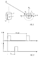
- FIG. 2 schematically shows a side view and top view of a preferred exemplary embodiment of a light detector used in the device according to the invention.
- This light detector comprises a light detection means L (for example a photodiode, infrared receiving diode) or the like, which need not be spatially resolving.
- This light detection means L is arranged centrally within a substantially hollow cylinder Z which has a column Sp which runs along its cylindrical outer wall.
- a fork light barrier GL is also arranged on the cylindrical outer wall, the light barrier being opened and closed by the gap Sp.
- This fork light barrier GL supplies a reference signal when the gap Sp passes through its light barrier, which is shown, for example, in the timing diagram in FIG. 3.
- the time curve of the measurement signals supplied by the fork light barrier GL is illustrated in the diagram section labeled GL.
- the measurement signals are in the form of two rectangular pulses, the spacing of which corresponds exactly to a 360 ° revolution of the gap Sp around the light detection means L. If the gap Sp rotates through an angle ⁇ after it has passed through the fork light barrier GL until the light beam emitted by the object RP falls on the light detection means L in the center of the hollow cylinder Z, the corresponding light detection means L supplies a signal to the evaluation device.
- This signal of the light detection means L is shown in FIG. 3 over time with the signal delivered by the fork light barrier GL. As can be seen from FIG.
- the two signals are offset by the time t ⁇ , from which the angle ⁇ can be concluded.
- the cylinder Z is driven, for example, by a speed-controlled electric motor which keeps the speed of the cylinder Z constant.
- the time interval T between two successive measurement signals of the fork light barrier GL corresponds to an angle ⁇ of 360 °. If the time offset t ⁇ between the signal measured by the light detection means L and the signal GL measured by the fork light barrier is set to the time interval T and multiplied by the angle 360 °, the angle ⁇ can be determined directly therefrom.
- the longitudinal axis of the cylinder Z is aligned parallel to the z direction. The angle ⁇ is thus measured in the xy plane.
- the one fixed reference point for the rotational position of the cylinder Z measures for example a Hall sensor, a special electronic Circuit that from the to the electric motor of the rotatable cylinder Z applied drive signal directly the rotational position of the cylinder Z delivers, etc.
- a further light detector unit D2 is now arranged perpendicular to the first light detector D1, as shown in more detail in the schematic side view of FIG. 4, the two light detector units D1 and D2 also measure two angles perpendicular to one another.
- the light detector D1 for example, measures an angle in the yz plane because its cylinder Z is aligned along the x-axis
- the light detector D2 measures an angle in the xz plane because the longitudinal axis of its cylinder Z in y-direction is aligned.
- Two such light detectors D1 and D2 can now form a light detector unit E1, which for example measure the azimuth angle ⁇ 1 and the elevation angle e 1 .
- such a pair of light detector units D1 and D2 can also form the second light detector unit E2, wherein the angles of the light detectors D1 and D2 of the second light detector unit E2 can be aligned like those of the first light detector unit E1.
- the second light detector unit E2 can comprise, for example, only one such light detector D1 or D2. 4 shows the two separate drive motors Mx and My (eg electric motors, etc.) for the two rotatable cylinders Z. Of course, only one drive motor can be used for both cylinders Z, which drives them via a corresponding gear.
- FIG. 5 shows a schematic side view of an alternative exemplary embodiment for a light detector unit E1 or E2.
- the width of the gap Sp varies along the cylindrical outer wall of the hollow cylinder Z.
- the gap width is greatest at an upper end and tapers linearly (V-shaped) toward the lower end of the gap Sp.
- a spatially resolving light detection means L Z is arranged in the center of the hollow cylinder Z.
- the spatially resolving light detection means L Z can be a CCD line which extends in the radial direction of the hollow cylinder Z and is arranged centrally in the interior of the hollow cylinder Z. This configuration is referred to below as light detection line L Z.
- the light spot width falling from the object RP onto the light detection line L Z varies.
- two such elevation angles e A and e B are shown for illustration purposes, which correspond to objects RP A and RP B. If the light from the object RP A falls through the slit S p onto the light detection line L Z , the light spot which is striking there is just as wide as is represented by the vertical dashed field. The light field falls through a narrower slit section of the V-shaped column Sp. When the light from the object RP B strikes the light detection line L Z , the light spot generated there is as large as through the vertically and horizontally dashed fields on the light detection line L Z is shown.
- the light falls through a wider slit section of the V-shaped column Sp.
- the azimuth angle ⁇ A, B is measured, for example, when the light spot - seen in the radial direction - strikes the light detection line L Z centrally. If the center of the light spot lies next to the center of the light detection line L Z , the center of the symmetrically formed gap Sp is not yet aligned in the direction of the object RP A, B.
- a cylinder with two columns Sp and Sp 2 can alternatively be used, as is shown in the schematic side view of FIG. 5b.
- the column width of the column Sp is constant, while the column width of the gap Sp 2 increases or decreases linearly from one end to the other end, as in the exemplary embodiment in FIG. 5a.
- the gap Sp is used here to measure the azimuth angle ⁇ A, B. Its measurement signal is also used to trigger the measurement of the elevation angle e A, B using the gap Sp 2 .
- a temporal pulse width measurement is preferably carried out.
- the evaluation device determines the pulse duration of the measured light signal. Since the entire light spot from its one edge to its other edge (for the object RP A the left and right edge of the vertically dashed field and for the object RP B the left and right edge of the horizontally dashed field) over the "center" of the light detection means is running, the pulse duration is different for the same rotational speed of the aperture and a measure of the elevation angle e A, B.
- the light detection means is preferably no longer spatially resolving.
- V-shaped gap Sp shown in FIGS. 5a and 5b
- other gap shapes can also be used which allow a clear assignment of the light spot projected onto a light detection line L Z or a non-location-resolving light detection means to the associated elevation angle.
- a non-linear increase or decrease can also be provided, for example in order to obtain a linear dependence of the detected light spot width or pulse duration on the elevation angle e A, B.
- a gap Sp with a constant gap width is provided on the cylindrical outer wall of the hollow cylinder Z, to which a further gap Sp 3 is arranged in a locally offset manner.
- this gap Sp 3 is shown opposite the gap Sp in FIG. 5c.
- the gap Sp 3 does not run parallel to the longitudinal axis of the hollow cylinder Z. For example, it can run obliquely to the longitudinal axis, so that the gap Sp 3 executes a spiral shape over the cylindrical outer surface of the hollow cylinder Z.
- the gap Sp is used to determine the azimuth angle ⁇ , as is shown in the timing diagram in FIG. 6.
- the azimuth angle ⁇ results from the time offset t ⁇ to a corresponding signal of the fork light barrier GL, not shown in FIG. 5c.
- the second light signal falling on the non-spatial resolution (point-shaped) light detection means L is used to measure the elevation angle e.
- the elevation angle e can thus be determined from the time offset of the light signal assigned to the first gap Sp and the light signal assigned to the second gap Sp 3 .
- any form of column Sp 3 is again conceivable here that enables the measured time offset t e to be uniquely assigned to the elevation angle e.
- the course of the gap Sp 3 can be chosen so that the measured time offset t e is linearly dependent on the elevation angle e.
- the hollow cylinder Z can also carry out exemplary embodiments have two, three or more columns in the circumferential direction evenly over the cylindrical outer wall of the hollow cylinder Z are distributed. With two such opposite The hollow cylinder Z can be compared in comparison to a hollow cylinder with only one gap constant Width driven at half the speed of rotation and still has the same temporal resolution rate, but at the cost of a halved detection space (Only objects RP "in front” of such a detector can be used be recorded, but not “behind” it). in the Case of a hollow cylinder Z with only one column Sp constant Two light detection cells can be wide L are used, whose detection surfaces face "forward" and point to the "back".
- the light detector is used so that it is always in one certain minimum distance from the object RP, three or more columns can also be provided, where is the angular range for position determination reduced accordingly (with three columns only one Angular range of 120 ° can be detected "in front" of the detector, Etc.).
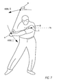
- Fig. 7 now shows a special application example of such an inventive device for determination the position of several objects in space.
- Application example shown is the movement of a Golfers are analyzed.
- a frequency selective reflector or one on a first frequency emitting light source
- a second frequency selective Reflector or a second light source that Light on a second, different from the first Frequency emits
- a third frequency selective reflector or a third light source, the light on a third, from the first and the second different frequency
- Such frequency-selective reflectors can, for example can be easily realized with color filters, e.g. incident white light in the corresponding Reflect the color of the color filter.
- the light detector units E1 and E2 can now be designed so that their Light detection means L are frequency selective. At a first rotation of the hollow cylinder H can the light detection means L only receive light of the first frequency, in the subsequent circulation only light of the second frequency and in a subsequent circulation only light the third frequency. Then it receives light again the first frequency. If the hollow cylinder Z three columns Sp, the frequency selectivity can also be within a third of the rotation of the hollow cylinder Z changed become. Thus, the positions of the Club head H, hand H and shoulder S determined become.
- These measured positions can be tracked over time and corresponding analyzes of the swing path (lever II) of the club head K, in particular the angle ⁇ between Golfers club and arm and shoulder angle Golf the golfer's horizontal ho, as well as the swing path (lever I) of the swing hand H des Golfers are analyzed.
- the Light detectors E1 and E2 also non-frequency selective be designed. In this case, the evaluation device starting from a e.g. entered manually Starting position of the club head K, the swing hand H and the shoulder S the positions of these objects in time follow.
- a first criterion for the assignment of a newly measured Position to one of the several tracked Trajectories whose spatial proximity to one of these trajectories and a second criterion regarding their location the direction of these trajectories, which were determined from the last Position is derived.
- a second criterion regarding their location the direction of these trajectories, which were determined from the last Position is derived.
- FDM frequency selective differentiation
- TDM time division multiplexing
- CDM code division multiplexing
- the invention can also in medical technology (e.g. orthopedics for Step or gait pattern measurement, etc.), the industry (e.g. measuring the position of a crane hook from Heavy-duty cranes, etc.), virtual reality (e.g. for a human / machine user interface in the form of a Data gloves, etc.) etc. are used.
- medical technology e.g. orthopedics for Step or gait pattern measurement, etc.
- industry e.g. measuring the position of a crane hook from Heavy-duty cranes, etc.
- virtual reality e.g. for a human / machine user interface in the form of a Data gloves, etc.
- the invention is also particularly suitable for position determination on a small scale.
Landscapes
- Physics & Mathematics (AREA)
- Electromagnetism (AREA)
- Engineering & Computer Science (AREA)
- General Physics & Mathematics (AREA)
- Radar, Positioning & Navigation (AREA)
- Remote Sensing (AREA)
- Computer Networks & Wireless Communication (AREA)
- Length Measuring Devices By Optical Means (AREA)
Applications Claiming Priority (2)
| Application Number | Priority Date | Filing Date | Title |
|---|---|---|---|
| DE2002146808 DE10246808A1 (de) | 2002-10-08 | 2002-10-08 | Verfahren und Vorrichtungen zum Bestimmen der Position eines Objektes im Raum |
| DE10246808 | 2002-10-08 |
Publications (2)
| Publication Number | Publication Date |
|---|---|
| EP1408342A2 true EP1408342A2 (fr) | 2004-04-14 |
| EP1408342A3 EP1408342A3 (fr) | 2004-08-04 |
Family
ID=32010371
Family Applications (1)
| Application Number | Title | Priority Date | Filing Date |
|---|---|---|---|
| EP03022887A Withdrawn EP1408342A3 (fr) | 2002-10-08 | 2003-10-08 | Méthode et dispositif pour la determination de la position d'un objet avec des moyens optiques |
Country Status (2)
| Country | Link |
|---|---|
| EP (1) | EP1408342A3 (fr) |
| DE (1) | DE10246808A1 (fr) |
Cited By (2)
| Publication number | Priority date | Publication date | Assignee | Title |
|---|---|---|---|---|
| FR2878615A1 (fr) * | 2004-11-30 | 2006-06-02 | Raquin Cyrille | Systeme de simulation de tir ou de lancement de projectile a l'aide d'un objet ou lanceur specifique |
| EP1536248A3 (fr) * | 2003-11-27 | 2006-12-06 | Deutsches Zentrum für Luft- und Raumfahrt e.V. | Procédé et dispositif pour suivre la position d'objets en mouvement |
Families Citing this family (1)
| Publication number | Priority date | Publication date | Assignee | Title |
|---|---|---|---|---|
| EP2201987B1 (fr) | 2008-12-29 | 2011-05-25 | ABATEC Electronic AG | Dispositif et procédé pour la détection du mouvement d'un club de golf |
Family Cites Families (8)
| Publication number | Priority date | Publication date | Assignee | Title |
|---|---|---|---|---|
| EP0063127A1 (fr) * | 1980-10-21 | 1982-10-27 | ARATO, Laszlo | Procede et installation de determination des coordonnees de deplacement pour le parcours telecommande d'un corps mobile |
| CH661981A5 (de) * | 1984-02-13 | 1987-08-31 | Haenni & Cie Ag | Optisches messgeraet zur beruehrungslosen abstandsmessung. |
| US4688933A (en) * | 1985-05-10 | 1987-08-25 | The Laitram Corporation | Electro-optical position determining system |
| US4997146A (en) * | 1989-05-30 | 1991-03-05 | Ford Aerospace Corporation | Electronic sun incidence avoidance device |
| DE4212438A1 (de) * | 1992-04-14 | 1993-10-21 | Dirk Prof Dr Ing Jansen | Anordnung zur Erzeugung eines lateralen Strahlversatzes bei Vorrichtungen zur trigonometrischen Distanzmessung |
| GB2285550B (en) * | 1994-01-05 | 1997-09-17 | Creo Products Inc | Optical coordinate measuring system for large objects |
| JPH07286839A (ja) * | 1994-04-18 | 1995-10-31 | Fujitsu Ten Ltd | 回転角センサ |
| DE10039384A1 (de) * | 2000-08-11 | 2002-02-21 | Buech Multimedia Kg | Verfahren und Vorrichtung zur Bestimmung von Positionsdaten von beweglichen Objekten, zur Auswertung von Ereignissen und/oder zur Bestimmung der Relationen zwischen beweglichen Objekten |
-
2002
- 2002-10-08 DE DE2002146808 patent/DE10246808A1/de not_active Ceased
-
2003
- 2003-10-08 EP EP03022887A patent/EP1408342A3/fr not_active Withdrawn
Cited By (2)
| Publication number | Priority date | Publication date | Assignee | Title |
|---|---|---|---|---|
| EP1536248A3 (fr) * | 2003-11-27 | 2006-12-06 | Deutsches Zentrum für Luft- und Raumfahrt e.V. | Procédé et dispositif pour suivre la position d'objets en mouvement |
| FR2878615A1 (fr) * | 2004-11-30 | 2006-06-02 | Raquin Cyrille | Systeme de simulation de tir ou de lancement de projectile a l'aide d'un objet ou lanceur specifique |
Also Published As
| Publication number | Publication date |
|---|---|
| EP1408342A3 (fr) | 2004-08-04 |
| DE10246808A1 (de) | 2004-04-22 |
Similar Documents
| Publication | Publication Date | Title |
|---|---|---|
| DE69804591T2 (de) | Positionserkennungssystem für virtuelles studio | |
| DE69702338T2 (de) | Verfahren und system zur manipulation von objekten in einem fernsehbild | |
| DE69819363T2 (de) | System zur bestimmung der räumlichen position und orientierung eines körpers | |
| DE19518978C2 (de) | Hinderniserfassungsvorrichtung für Kraftfahrzeuge | |
| DE69119500T2 (de) | System und Verfahren zur dreidimensionalen Positionserfassung | |
| DE10034976B4 (de) | Erfassungsvorrichtung zum Erfassen von Personen | |
| DE4230515C2 (de) | Strahlenbündelanordnung zur Verkehrsüberwachung | |
| DE102013104443A1 (de) | Verkehrsüberwachungssystem zur Geschwindigkeitsmessung und Zuordnung von bewegten Fahrzeugen bei einem Mehrziel-Aufnahmemodul | |
| EP1057323B1 (fr) | Systeme de poursuite de camera pour studio de television ou de video virtuel | |
| WO2009095014A1 (fr) | Procédé et dispositif de surveillance d'un volume spatial | |
| DE19621612A1 (de) | Verfahren und Vorrichtung zur optischen Freiraumüberwachung | |
| DE69224671T2 (de) | Räumliche positionierungsvorrichtung | |
| WO1992008948A1 (fr) | Procede et dispositif de mesure opto-electrique servant a determiner les dimensions de la section transversale d'objets notamment allonges par rapport a au moins une ligne droite tracee a la peripherie de la section transversale, touchant celle-ci en au moins deux points | |
| WO2001017838A1 (fr) | Procede pour la surveillance d'une zone de danger | |
| DE102015106837B4 (de) | Verfahren zur Steuerung einer 3D-Messvorrichtung mittels Gesten und Vorrichtung hierzu | |
| EP1408342A2 (fr) | Méthode et dispositif pour la determination de la position d'un objet avec des moyens optiques | |
| EP0997704A1 (fr) | Théodolite | |
| DE102011017707A1 (de) | Verfahren und Vorrichtung zur Erkennung von einem Objekt in einer Umgebung einer Kamera | |
| EP3989860A1 (fr) | Système de caméras | |
| DE102014204423B4 (de) | Lichtlaufzeitkamerasystem | |
| WO2012175185A1 (fr) | Dispositif et procédé pour étalonner la direction d'un appareil de mesure polaire | |
| DE102011107451B3 (de) | Verfahren und Vorrichtung zur Bestimmung der Position und Orientierung eines Körpers | |
| DE2405195A1 (de) | Vorrichtung zur abtastung eines dreidimensionalen gebildes | |
| DE10225077A1 (de) | Trackingsystem | |
| EP1769638A1 (fr) | Commande d'une camera asservie |
Legal Events
| Date | Code | Title | Description |
|---|---|---|---|
| PUAI | Public reference made under article 153(3) epc to a published international application that has entered the european phase |
Free format text: ORIGINAL CODE: 0009012 |
|
| AK | Designated contracting states |
Kind code of ref document: A2 Designated state(s): AT BE BG CH CY CZ DE DK EE ES FI FR GB GR HU IE IT LI LU MC NL PT RO SE SI SK TR |
|
| AX | Request for extension of the european patent |
Extension state: AL LT LV MK |
|
| PUAL | Search report despatched |
Free format text: ORIGINAL CODE: 0009013 |
|
| AK | Designated contracting states |
Kind code of ref document: A3 Designated state(s): AT BE BG CH CY CZ DE DK EE ES FI FR GB GR HU IE IT LI LU MC NL PT RO SE SI SK TR |
|
| AX | Request for extension of the european patent |
Extension state: AL LT LV MK |
|
| RIC1 | Information provided on ipc code assigned before grant |
Ipc: 7G 01S 5/16 B Ipc: 7G 01S 3/782 A |
|
| AKX | Designation fees paid | ||
| REG | Reference to a national code |
Ref country code: DE Ref legal event code: 8566 |
|
| STAA | Information on the status of an ep patent application or granted ep patent |
Free format text: STATUS: THE APPLICATION IS DEEMED TO BE WITHDRAWN |
|
| 18D | Application deemed to be withdrawn |
Effective date: 20050205 |