EP1408502A2 - Optisches Plattenlaufwerk mit erhöhter Aufzeichnungseffizienz - Google Patents
Optisches Plattenlaufwerk mit erhöhter Aufzeichnungseffizienz Download PDFInfo
- Publication number
- EP1408502A2 EP1408502A2 EP03255339A EP03255339A EP1408502A2 EP 1408502 A2 EP1408502 A2 EP 1408502A2 EP 03255339 A EP03255339 A EP 03255339A EP 03255339 A EP03255339 A EP 03255339A EP 1408502 A2 EP1408502 A2 EP 1408502A2
- Authority
- EP
- European Patent Office
- Prior art keywords
- data
- standard
- disk
- recorded
- format
- Prior art date
- Legal status (The legal status is an assumption and is not a legal conclusion. Google has not performed a legal analysis and makes no representation as to the accuracy of the status listed.)
- Withdrawn
Links
Images



Classifications
-
- G—PHYSICS
- G11—INFORMATION STORAGE
- G11B—INFORMATION STORAGE BASED ON RELATIVE MOVEMENT BETWEEN RECORD CARRIER AND TRANSDUCER
- G11B20/00—Signal processing not specific to the method of recording or reproducing; Circuits therefor
- G11B20/10—Digital recording or reproducing
- G11B20/12—Formatting, e.g. arrangement of data block or words on the record carriers
- G11B20/1217—Formatting, e.g. arrangement of data block or words on the record carriers on discs
-
- G—PHYSICS
- G11—INFORMATION STORAGE
- G11B—INFORMATION STORAGE BASED ON RELATIVE MOVEMENT BETWEEN RECORD CARRIER AND TRANSDUCER
- G11B20/00—Signal processing not specific to the method of recording or reproducing; Circuits therefor
- G11B20/10—Digital recording or reproducing
- G11B20/12—Formatting, e.g. arrangement of data block or words on the record carriers
-
- G—PHYSICS
- G11—INFORMATION STORAGE
- G11B—INFORMATION STORAGE BASED ON RELATIVE MOVEMENT BETWEEN RECORD CARRIER AND TRANSDUCER
- G11B20/00—Signal processing not specific to the method of recording or reproducing; Circuits therefor
- G11B20/10—Digital recording or reproducing
-
- G—PHYSICS
- G11—INFORMATION STORAGE
- G11B—INFORMATION STORAGE BASED ON RELATIVE MOVEMENT BETWEEN RECORD CARRIER AND TRANSDUCER
- G11B20/00—Signal processing not specific to the method of recording or reproducing; Circuits therefor
- G11B20/10—Digital recording or reproducing
- G11B20/12—Formatting, e.g. arrangement of data block or words on the record carriers
- G11B20/1262—Formatting, e.g. arrangement of data block or words on the record carriers with more than one format/standard, e.g. conversion from CD-audio format to R-DAT format
-
- G—PHYSICS
- G11—INFORMATION STORAGE
- G11B—INFORMATION STORAGE BASED ON RELATIVE MOVEMENT BETWEEN RECORD CARRIER AND TRANSDUCER
- G11B20/00—Signal processing not specific to the method of recording or reproducing; Circuits therefor
- G11B20/10—Digital recording or reproducing
- G11B20/18—Error detection or correction; Testing, e.g. of drop-outs
- G11B20/1833—Error detection or correction; Testing, e.g. of drop-outs by adding special lists or symbols to the coded information
- G11B2020/1836—Error detection or correction; Testing, e.g. of drop-outs by adding special lists or symbols to the coded information using a Reed Solomon [RS] code
-
- G—PHYSICS
- G11—INFORMATION STORAGE
- G11B—INFORMATION STORAGE BASED ON RELATIVE MOVEMENT BETWEEN RECORD CARRIER AND TRANSDUCER
- G11B2220/00—Record carriers by type
- G11B2220/20—Disc-shaped record carriers
- G11B2220/25—Disc-shaped record carriers characterised in that the disc is based on a specific recording technology
- G11B2220/2537—Optical discs
- G11B2220/2545—CDs
-
- G—PHYSICS
- G11—INFORMATION STORAGE
- G11B—INFORMATION STORAGE BASED ON RELATIVE MOVEMENT BETWEEN RECORD CARRIER AND TRANSDUCER
- G11B2220/00—Record carriers by type
- G11B2220/20—Disc-shaped record carriers
- G11B2220/25—Disc-shaped record carriers characterised in that the disc is based on a specific recording technology
- G11B2220/2537—Optical discs
- G11B2220/2562—DVDs [digital versatile discs]; Digital video discs; MMCDs; HDCDs
Definitions
- the present invention relates to an optical disk drive capable of recording data onto a disk based on a disk format of an existing standard in which the data to be recorded is in a data format compliant with a more efficient data formatting standard than the standard for the disk.
- the present invention relates to an optical disk drive suitable for recording data onto a recordable disk based on a CD standard in which the data to be recorded is generated in a data format compliant with a DVD standard.
- CD compact disc
- DVD digital versatile disc
- a DVD drive for such a DVD ensures upward compatibility with a CD, and most are capable of playing CDs.
- the recording capacity of a disk As for the recording capacity of a disk, much more data can be recorded on a DVD than on a CD. As the amount of data in files used on personal computers has increased, the recording capacities of both a CD-R and a CD-RW, which are typically 650 MB and 700 MB, respectively, are more and more commonly found to be insufficient.
- Fig. 5 shows a data structure of audio data (included in one sector) in a data format based on a CD-DA standard which is an audio standard for a CD, after expansion by a decoding process based on the CD-DA standard.
- Fig. 6 shows a data structure of data (included in sixteen sectors) in a data format based on a DVD standard, after expansion by a decoding process based on the DVD standard.
- the data structure based on the CD-DA standard does not include a header, an error detection code (EDC), or an error correction code (ECC), all of which are included in the data structure based on the DVD standard.
- EDC error detection code
- ECC error correction code
- the data structures based on the CD-DA and DVD standards differ in that the former contains 2352 bytes of user data while the latter contains 2048 bytes of user data.
- one sector of CD-DA data does not fit into one sector based on the DVD standard.
- the CD-DA data can be recorded in the data format of the DVD standard, there is still a problem in that the data cannot be read without being processed because the data structures differ from each other.
- the present invention was conceived to provide an optical disk drive wherein data is written onto a recordable disk based on a disk format of a predetermined standard and according to an existing data format with format efficiency higher than the predetermined standard to thereby enable the data to be written in high-density recording mode, and wherein audio data is written and read to and from a disk according to a data format which differs from that of the audio data.
- an optical disk drive comprises a first recording signal processor for performing signal processing on input data so as to generate data to be recorded which is based on a data format compliant with a common first standard and a second recording signal processor for performing signal processing on input data so as to generate data to be recorded which is based on a data format compliant with a second standard having a format efficiency higher than the data format of the first standard, wherein one of the first and second recording signal processors can be selectively used during recording to a recordable disk based on the first standard.
- an optical disk drive comprises a first reproducing signal processor for performing signal processing on data read from a disk so as to decode the recorded data based on the data format compliant with the first standard and a second reproducing signal processor for performing signal processing on data read from a disk so as to decode the recorded data based on the data format compliant with the second standard, wherein a determination is made as to whether the data read from the disk based on the first standard is based on the data format compliant with the first standard or the second standard, so that the readout data is supplied to the first reproducing signal processor when the data is determined to be based on the data format compliant with the first standard and the data is supplied to the second reproducing signal processor when the data is determined to be based on the data format compliant with the second standard.
- the data is determined to be based on the data format compliant with the second standard, it is determined whether or not the data to be reproduced which is decoded by the second reproducing signal processor is audio data.
- the data to be reproduced is identified as audio data, only user data is transferred into a D/A converter at a sampling rate suitable for audio reproduction from a memory storing the data to be reproduced.
- Fig. 1 is a circuit block diagram showing an embodiment of an optical disk drive according to the present invention.
- the optical disk drive shown in Fig. 1 is a new type of CD-R/CD-RW drive which is capable of writing and reading data to and from a CD and reading data from a DVD, and, at the same time, the drive is capable of performing a recording process and a reproducing process of signals according to a data format based on a DVD standard.
- the CD-R/CD-RW drive includes an optical head 1 for writing data to and reading data signals from a disk using a laser emitted for tracing signal tracks formed on the disk.
- the optical head 1 includes, as light sources, a first laser diode 1a for use in writing and reading data onto and from a CD and a second laser diode 1b for use in reading data from a DVD.
- the first laser diode 1a emits a beam of focused a laser with a wavelength of 780 nm
- the second laser diode 1b emits a laser beam with a wavelength of 650 nm.
- the laser beams emitted from the respective laser diodes 1a and 1b are adjustable to be focused on their associated disks such as a CD and a DVD through a dual-focal-length objective lens (not shown).
- the optical disk drive further includes a front-end processor 2 which generates an RF signal (radio frequency signal) corresponding to a data signal read from a disk using various types of photoreceiver outputs from the optical head 1, applies a gain control to the RF signal to an optimum level, equalizes the RF signal according to the type of a disk to obtain binary data, and generates a focus error signal representing the amount of deviation of a laser beam emitted from the optical head 1 to a signal surface of the disk, and a tracking error signal representing the amount of deviation of a laser beam from a signal track on a disk.
- RF signal radio frequency signal
- the optical disk drive further includes a head servo circuit 3.
- the head servo circuit 3 performs focus control responsive to the focus error signal so that a main beam is focused on a signal surface of a disk, performs tracking control responsive to the tracking error signal so that the main beam traces a signal track of a disk, and performs thread advance control so that the optical head 1 is advanced in a radial direction of a disk.
- the optical disk drive further includes an ATIP (absolute time in pre-groove) decoder 4 for decoding a wobble signal sampled from a pre-groove on a CD-type recordable disk (CD-R or CD-RW) using the front-end processor 2, to obtain an ATIP address as an address for providing time information.
- ATIP absolute time in pre-groove
- the optical disk drive further includes a CD decoder 5.
- the decoder 5 is used to decode data read from a disk using the front-end processor 2, according to a data format defined by a CD standard.
- the CD standard employs the EFM (eight to fourteen modulation) code as a modulation code, and also employs the CIRC (cross interleaved Reed-Solomon code) as an error correction code.
- the CD decoder 5 decodes data according to these modulation and error correction codes.
- the optical disk drive further includes a DVD decoder 6.
- the decoder 6 is used to decode data read from a disk using the front-end processor 2, according to a data format defined by a DVD standard.
- the DVD standard employs the EFM-Plus (eight to sixteen modulation) code as a modulation code, and also employs the RS (Reed-Solomon) product code as an error correction code.
- the DVD decoder 6 decodes data according to these modulation and error correction codes.
- the optical disk drive further includes a D/A converter 7 for converting digital audio data to analog data and outputting the analog data from audio output terminals 8 and 9.
- the digital-to-analog conversion is carried out after audio data based on the CD-DA standard is obtained through decoding by the CD decoder 5 or the DVD decoder 6.
- the optical disk drive further includes an interface 10 for controlling data transfer between the drive and a host device such as a personal computer. Connection between the interface 10 and the host device is established via a connecting terminal 11.
- the optical disk drive further includes a CD encoder 12.
- the CD encoder 12 is used to encode input data input through the interface 10, according to a data format defined by a CD standard, to thereby generate CD data with a data structure based on the CD data format.
- the optical disk drive further includes a DVD encoder 13 .
- the DVD encoder 13 is used to encode input data input through the interface 10, according to a data format defined by a DVD standard, to thereby generate DVD data with a data structure based on the DVD data format.
- the optical disk drive further includes a RAM 14, a memory controller 15, and a system control microprocessor 16.
- the RAM 14 is used to temporarily store the data input through the interface 10, and is used while the CD encoder 12 or the DVD encoder 13 encodes data and while the CD decoder 5 or the DVD decoder 6 decodes data.
- the RAM 14 is also used to store the decoded data to be reproduced.
- the memory controller 15 controls writing and reading of data onto and from the RAM 14.
- the system control microprocessor 16 controls the overall system for writing and reading data onto and from a disk.
- the optical disk drive further includes a write strategy circuit 17 and a laser driving circuit 18.
- the write strategy circuit 17 is used to control light emission power from the optical head 1 to thereby perform an optimum write operation for a disk in consideration of recording characteristics of disks including a CD-R and a CD-RW.
- the laser driving circuit 18 is used to drive the first or second laser diode 1a or 1b under the control of an APC (automatic power control) circuit (not shown) which is included in the front-end processor 2 .
- the laser driving circuit 18 is used to drive the first laser diode 1a of the optical head 1 responsive to a pulse signal generated from the write strategy circuit 17.
- the optical disk drive further includes a spindle motor 19 for rotationally driving a disk, a motor driving circuit 20 for driving the spindle motor 19, and a motor control circuit 21 for controlling the motor driving circuit 20.
- the motor control circuit 21 is capable of controlling rotation in constant linear velocitymode using a bit clock and a synchronization signal sampled from data signals stored on a disk, or in synchronization with an ATIP signal decoded by the ATIP decoder 4.
- the motor control circuit 21 is also capable of controlling rotation in constant angular velocity mode using a pulse signal generated responsive to rotation of the spindle motor 19.
- the optical disk drive shown in Fig. 1 is not only capable of playing a CD and a DVD and capable of recording on a CD-R or CD-RW disk in normal recording mode compliant with either CD standard, but is also capable of recording on a CD-R or CD-RW disk in a high-density recording mode in which data generated in a DVD data format is recorded.
- the optical disk drive is not adapted to DVD recording as commonly understood, that is, recording of data onto a recordable DVD, it should be understood that the optical disk drive can easily be adapted to enable such DVD recording.
- a CD-R/CD-RW disk is formed in a disk format such that a PCA (power calibration area), a PMA (program memory area), a lead-in area, a pre-gap area, a program area, and a lead-out area are included in this order from an inner region of the disk.
- PCA power calibration area
- PMA program memory area
- the PCA includes a test area where test writing is carried out and a counter area where a count of how many times test writing has been carried out is stored.
- the PMA is used as an area for temporarily storing disk information on a track and data now in the process of being recorded onto a disk until a session closes.
- the lead-in area is used to record the disk information stored in the PMA as a TOC (table of contents) at the close of the session.
- a disk format to be employed for high-density recording mode is of a specific type which differs from that for a CD-R/CD-RW.
- the disk format for high-density recording mode includes a PCA, a format area, a PMA (including a TOC area) , a program area, and a lead-out area. These areas are formed in this order from an inner region of a disk.
- the PCA corresponds to the PCA
- the format area corresponds to the PMA
- the PMA including the TOC area
- the lead-in area corresponds to the lead-in area.
- the corresponding areas in the CD-R/CD-RW disk format are shown in brackets.
- the lead-in area in the disk format for a CD-R/CD-RW is used as the PMA including the TOC area.
- the PMA has a main channel for recording PMA data (PMD), which also functions as the TOC data in the disk format for a CD.
- PMD PMA data
- the PMA data is used as data (PMD) corresponding to the TOC data (in this case, a lead-in of the PMA data is provided at the beginning).
- a format command specific to high-density recording mode is executed for entirely padding the format area with specific data unrelated to the PMA.
- the specific data may consist of, for example, a string of zeroes or device information data, such as a manufacturer identifying code, a model number, a serial number, a code indicating that a disk format is for high-density recording mode.
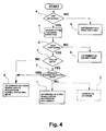
- FIG. 4 shows a flowchart of a routine for determining the type of a disk in use.
- the first laser diode 1a of the optical head 1 is driven by the laser driving circuit 18 so as to reach a playable condition according to the amount of light reflected from the disk.
- the ATIP signal on the disk is detected, enabling disk-determining means 22 to determine whether the disk is a recordable disk or a read-only disk (step a). If the ATIP signal is not detected at this step, it is determined that the disk is a read-only disk (step b).
- the disk when the disk is determined as a read-only disk, a further operation is performed to determine whether the disk is a CD or a DVD.
- the disk is determined to be a recordable disk, more specifically, a CD-R or a CD-RW disk. After this has been determined, the PMA in the disk format on the recordable CD is accessed in an attempt to detect a signal in this area (step c).
- step d it is determined whether or not the PMA contains data. If at this step it is determined that the PMA contains no data, the disk is determined to be an empty disk (step e).
- step f if it is determined that the PMA contains data, it is subsequently determined as to whether or not the entire area of the PMA contains recorded data.
- step g If it is determined that the PMA is not completely full of data, it is determined that the disk is written in a normal recording mode.
- step h If the PMA is found to be filled with data, it is then determined whether or not the data is readable by attempting to decode the data in a manner appropriate for PMA data written in a normal recording mode.
- step i When data in the PMA determined to be full of data is written in normal recording mode, it is next determined as to whether or not the data is readable by attempting to decode in a manner suitable for the PMA. If the data is not readable and is determined to be data unrelated to the PMA for normal recording mode, it is determined that the data was writtenon the diskusing a high-density recording mode (step i) . On the other hand, if the data is readable and is determined as being relevant to the PMA for normal recording mode, it is determined that the data was written on the disk in a normal recording mode (step g).
- the host device connected to the connecting terminal 11 sends a write command, and thereby requests writing of data onto a disk in the normal recording mode.
- the system control microprocessor 16 sets conditions for the writing of data onto a disk according to the disk format for a recordable CD. More specifically, the system control microprocessor 16 switches the circuits to the settings for writing data onto a disk in the normal recording mode, and selects a recording signal processing system which incorporates the CD encoder 12.
- the respective settings are selected so as to enable an operation suitable for the writing of data onto a disk in the normal recording mode according to the determined type of the disk.
- the motor control circuit 21 controls the motor driving circuit 20 so that the disk is driven at a rotational speed corresponding to the recording speed set by the system control microprocessor 16.
- the write strategy circuit 17 controls the laser driving circuit 18 according to the set recording speed, so that the light emission power from the first laser diode 1a of the optical head 1 is set to a recording level which is preset to correspond to the recording speed.
- the PMA on the disk is searched using ATIP information.
- data in the PMA is read to confirm that a session has not closed.
- disk information data is retrieved to ascertain whether or not additional data can be written onto the disk, and to obtain an address at which data can be written.
- test writing is carried out in the PCA of the disk at the selected recording speed while gradually changing the light emission power.
- the light emission power from the optical head 1 is set to an optimum recording level at which the error rate in reading of the written data is minimized.
- the optical disk drive receives these command and data via the interface 10.
- the data requested to be written is stored in the RAM 14 under the control of the memory controller 15.
- the stored data is read out from the RAM 14 and input to the CD encoder 12 under the control of the memory controller 15.
- the CD encoder 12 operates under the control of the system control microprocessor 16, and encodes the input data to generate CD data having a data structure based on a data format defined by the CD standard.
- the CD data is supplied to the write strategy circuit 17.
- the write strategy circuit 17 generates recording pulses based on the CD data in consideration of the recording characteristics of a CD-R or a CD-RW according to the type of the disk, so as to write the data onto the disk at the optimum recording level which is selected through the test writing in the PCA.
- the recording pulses are used to drive the first laser diode 1a of the optical head 1, thereby enabling the data to be written onto the disk.
- recording marks based on the CD data are formed on the disk responsive to the recording pulses.
- the system control microprocessor 16 sets conditions for writing data onto the disk according to the disk format for the high-density recording mode. More specifically, the system control microprocessor 16 switches the circuits to the settings for writing data onto the disk in the high-density recording mode, and selects a recording signal processing system which incorporates the DVD encoder 13.
- the head servo circuit 3 In the front-end processor 2, the head servo circuit 3, the write strategy circuit 17, and the laser driving circuit 18, the respective settings are selected so as to enable an operation suitable for the writing of data onto a disk in the high-density recording mode and according to the determined type of the disk.
- the motor control circuit 21 controls the motor driving circuit 20 so that the disk is driven at a rotational speed corresponding to the recording speed set by the system control microprocessor 16.
- the write strategy circuit 17 controls the laser driving circuit 18 according to the set recording speed, so that the light emission power from the first laser diode 1a of the optical head 1 is set to a recording level which is preset to correspond to the recording speed.
- the writing in high-density recording mode is permitted only when the disk is determined to be capable of being written on in the high-density recording mode through the above-described determination steps.
- the PMA on the disk is searched using ATIP information.
- the PMA is located in an area corresponding to the lead-in area in the disk format for a recordable CD. Therefore, this area is searched for PMA data. As in the case of the normal recording mode, PMA data in this area is read to confirm that a session has not closed. Also, disk information data is retrieved to ascertain whether or not additional data can be written onto the disk, and to obtain an address at which data can be written.
- test writing is carried out in the PCA of the disk according to the disk format for the high-density recording mode at the selected recording speed while gradually changing the light emission power. Based on the results of the test writing, the light emission power from the optical head 1 is set to an optimum recording level such that the error rate in reading the written data is minimized.
- an actual recording address is calculated by multiplying an address A of ATIP by a recording density, and every unit of data is recorded using this actual recording address.
- a recording density per unit period is increased.
- a recording density to be used in multiplication is preset to n times (n > 1) the normal density, an actual recording address is equivalent to n times the address A of ATIP.
- the optical disk drive receives these command and data via the interface 10, and the data requested to be written is stored in the RAM 14.
- the DVD encoder 13 encodes the data to generate DVD data having a data structure based on a data format defined by the DVD standard.
- the DVD data is supplied to the write strategy circuit 17.
- the write strategy circuit 17 generates recording pulses based on the DVD data in consideration of the recording characteristics of a CD-R or a CD-RW according to the type of the disk, so as to enable writing of the data onto the disk at the optimum recording level which is selected through the test writing in the PCA.
- the recording pulses are used to drive the first laser diode 1a of the optical head 1, thereby enabling the data to be written onto the disk.
- recording marks based on the DVD data are formed on the disk responsive to the recording pulses.
- the data to be recorded in the program area is written in a file structure based on the ISO 9660 standard for logical formatting of a CD-ROM.
- a minimum unit of a sector is 2 kbytes, and a unit of recording is 32 kbytes, as required to generate an error correction code.
- the data format defined by the DVD standard includes less redundancy than the data format defined by the CD standard. Because of this difference in redundancy between these data formats, the data format of the DVD standard has a format efficiency 1.49 times that of the CD standard.
- the actual recording address for data to be written onto a disk is n times (n > 1) the corresponding address of ATIP.
- n the corresponding address of ATIP.
- the high-density recording mode can be used to record at a recording density approximately twice that of the normal recording mode.
- the host device When data to be recorded is CD-DA data, the host device sends 2352 bytes of audio data per sector (having a data structure shown in Fig. 5) .
- the audio data is written into the RAM 14 under the control of the memory controller 15.
- the amount of data stored in the RAM 14 reaches an amount for initiating the encoding process, or, more specifically, when the amount of data stored in the RAM 14 reaches an amount equivalent to 16 sectors of user data (2048 bytes) based on the data format for a DVD, that is, 32 kbytes, which is calculated by multiplying 2048 bytes by 16, the stored data is read out from the RAM 14 under the control of the memory controller 15 . This data is then encoded using the DVD encoder 13.
- the DVD encoder 13 adds headers, error detection codes, and error correction codes to the input data using the RAM 14 to thereby convert the data into data having a data structure shown in Fig . 6 . Then, modulation is performed on the resultant data using the EFM-Plus (8-16) code to generate DVD data.
- the amount of one sector of data which is sent by the host device according to the CD-DA standard is 2352 bytes, whereas the amount of user data to be written is 2048 bytes according to the DVD standard.
- per sector 304 bytes of audio data remain to be written. The remaining audio data is sequentially incorporated into the next sector, and reassignment is carried out so that one sector consists of 2048 bytes.
- the sector unit is completed by padding a remaining and available capacity for data region with zeroes until the amount of data reaches 2048 bytes.
- an identifier for identifying the data as audio data is added to the header of each sector.
- the lead-in area also records the PMA data which contains identification data for identifying an audio track in which audio data is recorded.
- the host device sends a read command, and thereby requests reading of data from a disk.
- the system control microprocessor 16 switches the circuits to the settings for reading a disk. More specifically, in the front-end processor 2, the head servo circuit 3, and the laser driving circuit 18, the respective settings are selected so as to enable an operation suitable for the disk to be read, while a laser diode to be used in the optical head 1 and a decoder to be used are selected, so that conditions are set for reading a disk according to the type of disk which is determined through the determination steps when the disk is first inserted.
- the laser driving circuit 18 drives the first laser diode 1a of the optical head 1 while setting the light emission power to a level suitable for a read operation according to the type of disk.
- data is read out from a disk D using the optical head 1.
- the readout signal from the disk D is subjected to signal processing suitable for CD, and an RF signal is converted into a binary signal to generate CD data.
- the CD data is stored in the RAM 14 under the control of the memory controller 15. Then, the CD data stored in the RAM 14 is decoded by the CD decoder 5 in units for performing error correction (32 kbytes).
- the front-end processor 2 generates a focus error signal and a tracking error signal. These signals are generated through steps suitable for CD and then supplied to the head servo circuit 3.
- the CD data decoded by the CD decoder 5 is demodulated according to the data format of the CD standard to form request data which is to be sent to the host device.
- data includes a subcode having an identification code added to the Q signal in a control area for identifying whether the data is CD-DA data or CD-ROM data.
- the subcode Q signal is decoded during the decoding process by the CD decoder 5, thereby enabling identification of the data being reproduced as either CD-DA data or CD-ROM data.
- the data is CD-ROM data
- the CD data decoded by the CD decoder 5 is temporarily stored in the RAM 14 as needed. Subsequently, the data is supplied via the interface 10 to the host device which is connected to the connecting terminal 11.
- the data is CD-DA data
- the CD data decoded by the CD decoder 5 is subjected to digital-to-analog conversion by the D/A converter 7 and is converted into an analog signal.
- the resulting signal is output from the audio output terminals 8 and 9.
- the laser driving circuit 18 drives the second laser diode 1b of the optical head 1 while setting the light emission power to a level suitable for a read operation according to the type of disk.
- data is read out from a disk D using the optical head 1.
- the readout signal from the disk D is subjected to signal processing suitable for DVD, and an RF signal is converted into a binary signal to generate DVD data.
- the DVD data is stored in the RAM 14 under the control of the memory controller 15. Then, the DVD data stored in the RAM 14 is decoded by the DVD decoder 6 in units for performing error correction (32 kbytes) .
- the front-end processor 2 generates a focus error signal and a tracking error signal. These signals are generated through steps suitable for DVD and then supplied to the head servo circuit 3.
- the DVD data supplied to the DVD decoder 6 is demodulated through the decoding process according to the data format of the DVD standard by the DVD decoder 6 to form request data which is to be sent to the host device.
- This data is temporarily stored in the RAM 14 as needed, and then supplied via the interface 10 to the host device which is connected to the connecting terminal 11.
- the laser driving circuit 18 drives the first laser diode 1a of the optical head 1 while setting the light emission power to a level suitable for a read operation according to the type of disk.
- data is read out from a disk D using the optical head 1.
- the reading out of data from the disk D is carried out through steps according to the disk format for the high-density recording mode.
- the readout signal from the disk D is subjected to signal processing suitable for DVD, and an RF signal is converted into a binary signal to generate DVD data.
- the DVD data is stored in the RAM 14 under the control of the memory controller 15. Then, the DVD data stored in the RAM 14 is decoded by the DVD decoder 6 in units for performing error correction (32 kbytes).
- the front-end processor 2 generates a focus error signal and a tracking error signal. These signals are generated through steps suitable for a recordable CD and then supplied to the head servo circuit 3.
- the DVD data supplied to the DVD decoder 6 is demodulated through the decoding process according to the data format of a DVD standard by the DVD decoder 6 to form request data which is to be sent to the host device.
- This data is temporarily stored in the RAM 14 as needed, and then supplied via the interface 10 to the host device which is connected to the connecting terminal 11.
- the readout of data from the disk D is carried out through steps according to the disk format for the high-density recording mode .
- the front-end processor 2 generates DVD data through signal processing suitable for DVD, and the DVD data is stored in the RAM 14 under the control of the memory controller 15. Then, the DVD data stored in the RAM 14 is decoded by the DVD decoder 6 in units for performing error correction (32 kbytes).
- header-decoding means 23 provided in the system control microprocessor 16 decodes header information included in each sector. Because the header information includes an identifier indicating that the data is CD-DA data, the DVD data being reproduced is easily recognized as CD-DA data.
- data to be expanded in the RAM 14 after being decoded by the DVD decoder 6 has a data structure wherein a header, user data, an error detection code (EDC) , and an error correction code (ECC) are included in this order.
- EDC error detection code
- ECC error correction code
- the system control microprocessor 16 When the header-decoding means 23 detects an identifier indicating that the data is CD-DA data, the system control microprocessor 16 provides instructions for the memory controller 15 to transfer only the user data to the D/A converter 7 from among the data expanded in the RAM 14 and to skip the other data while counting the amount of data. At this time, operating clocks to be supplied to the memory controller 15 are based on the sampling frequency of CD-DA data. Thus, the data is transferred to the D/A converter 7 at a sampling rate suitable for CD-DA data.
- the D/A converter 7 converts only CD-DA data from a digital signal into an analog signal at the sampling rate for CD-DA data so that the audio signal according to the CD-DA data is properly output from the output terminals 8 and 9.
- Zeros are used to fill the remaining area for user data in the last sector of a unit of recording is not transferred to the D/A converter 7, because when a predetermined number of zeros representing non-audio signals are consecutively detected, the data can be recognized.
- the CD decoder 5 the DVD decoder 6 , the CD encoder 12 , and the DVD encoder 13 are shown in Fig. 1 by separate blocks, these circuits may be usually formed using an LSI where all these circuits are integrated.
- an optical disk drive can record audio data based on a predetermined standard onto a recordable disk based on a disk format of the standard in a high-density recording mode according to a data format having higher format efficiency than the standard.
- the optical disk drive can play a disk on which audio data is recorded in a high-density recording mode.
- an identifier for identifying data as audio data is added to a header, a sector wherein audio data is recorded can be reliably identified during replay of the disk.
- the optical disk drive can recognize, upon insertion of the disk, whether or not the disk includes an audio track on which audio data is recorded.
Landscapes
- Engineering & Computer Science (AREA)
- Signal Processing (AREA)
- Multimedia (AREA)
- Optical Recording Or Reproduction (AREA)
- Signal Processing For Digital Recording And Reproducing (AREA)
Applications Claiming Priority (2)
| Application Number | Priority Date | Filing Date | Title |
|---|---|---|---|
| JP2002278998A JP2004118910A (ja) | 2002-09-25 | 2002-09-25 | 光ディスク装置 |
| JP2002278998 | 2002-09-25 |
Publications (2)
| Publication Number | Publication Date |
|---|---|
| EP1408502A2 true EP1408502A2 (de) | 2004-04-14 |
| EP1408502A3 EP1408502A3 (de) | 2007-05-09 |
Family
ID=31987081
Family Applications (1)
| Application Number | Title | Priority Date | Filing Date |
|---|---|---|---|
| EP03255339A Withdrawn EP1408502A3 (de) | 2002-09-25 | 2003-08-28 | Optisches Plattenlaufwerk mit erhöhter Aufzeichnungseffizienz |
Country Status (6)
| Country | Link |
|---|---|
| US (1) | US20040057363A1 (de) |
| EP (1) | EP1408502A3 (de) |
| JP (1) | JP2004118910A (de) |
| KR (1) | KR100549749B1 (de) |
| CN (1) | CN1280821C (de) |
| TW (1) | TWI223233B (de) |
Cited By (1)
| Publication number | Priority date | Publication date | Assignee | Title |
|---|---|---|---|---|
| EP1349163A3 (de) * | 2002-03-18 | 2007-04-04 | Sanyo Electric Co., Ltd. | Optisches Plattengerät |
Families Citing this family (14)
| Publication number | Priority date | Publication date | Assignee | Title |
|---|---|---|---|---|
| US7233550B2 (en) | 2002-09-30 | 2007-06-19 | Lg Electronics Inc. | Write-once optical disc, and method and apparatus for recording management information on write-once optical disc |
| KR20040028469A (ko) | 2002-09-30 | 2004-04-03 | 엘지전자 주식회사 | 1 회 기록 가능한 광디스크의 디펙트 영역 관리방법 |
| ES2340844T3 (es) | 2002-12-11 | 2010-06-10 | Lg Electronics, Inc. | Metodo de gestion de sobrescritura y metodo de grabacion de informacion de gestion de un disco optico de una sola escritura. |
| US7355934B2 (en) | 2003-01-27 | 2008-04-08 | Lg Electronics Inc. | Optical disc of write once type, method, and apparatus for managing defect information on the optical disc |
| AU2004237020B2 (en) | 2003-05-09 | 2009-10-22 | Lg Electronics Inc. | Write once optical disc, and method and apparatus for recovering disc management information from the write once optical disc |
| KR20050009031A (ko) | 2003-07-15 | 2005-01-24 | 엘지전자 주식회사 | 1회 기록 가능한 광디스크 및 광디스크의 관리정보 기록방법 |
| US7313065B2 (en) | 2003-08-05 | 2007-12-25 | Lg Electronics Inc. | Write-once optical disc, and method and apparatus for recording/reproducing management information on/from optical disc |
| KR101041819B1 (ko) | 2003-09-08 | 2011-06-17 | 엘지전자 주식회사 | 1회 기록가능한 광디스크 및 광디스크상에 관리 정보를기록하기 위한 방법 |
| CA2537889C (en) | 2003-09-08 | 2013-10-22 | Lg Electronics Inc. | Write-once optical disc, and method and apparatus for recording management information on the write-once optical disc |
| EP1665261B1 (de) | 2003-09-08 | 2013-11-27 | LG Electronics Inc. | Einmal beschreibbarer optischer datenträger und verfahren und vorrichtung zum aufzeichnen von managementinformationen auf dem einmal beschreibbaren optischen datenträger |
| US20050083808A1 (en) * | 2003-09-18 | 2005-04-21 | Anderson Hans C. | Audio player with CD mechanism |
| CN101233572B (zh) * | 2005-07-29 | 2010-06-02 | 松下电器产业株式会社 | 数据重放装置 |
| JP4799475B2 (ja) * | 2007-04-27 | 2011-10-26 | 株式会社東芝 | 情報記録装置及び情報記録方法 |
| US8244935B2 (en) * | 2010-06-25 | 2012-08-14 | Oracle International Corporation | Write aggregation using optional I/O requests |
Family Cites Families (12)
| Publication number | Priority date | Publication date | Assignee | Title |
|---|---|---|---|---|
| TW307862B (de) * | 1995-06-20 | 1997-06-11 | Sony Co Ltd | |
| US6151442A (en) * | 1996-07-08 | 2000-11-21 | Victor Company Of Japan, Ltd. | Signal compressing apparatus |
| KR100256662B1 (ko) * | 1996-03-21 | 2000-05-15 | 니시무로 타이죠 | 데이타 기록 또는 전송을 위한 데이타 배치 방법 및 매체와 그 처리 장치 |
| KR100208714B1 (ko) * | 1996-06-14 | 1999-07-15 | 윤종용 | 다종 광디스크 선택적 재생시스템 |
| US5963705A (en) * | 1996-10-04 | 1999-10-05 | Samsung Electronics Co., Ltd. | Disk detecting device and method |
| KR100197623B1 (ko) * | 1996-10-24 | 1999-06-15 | 윤종용 | 디스크종류판별방법 및 이를 적용한 dvd시스템 |
| JP3239863B2 (ja) * | 1998-11-27 | 2001-12-17 | 日本電気株式会社 | データ復号処理装置および方法 |
| US6466736B1 (en) * | 1998-12-31 | 2002-10-15 | Oak Technology, Inc. | Integrated DVD/CD controller |
| KR100335439B1 (ko) * | 1999-03-25 | 2002-05-04 | 윤종용 | Dvd 응용 세션을 포함하는 멀티세션 디스크, 기록 및/또는 재생 장치와 방법 |
| KR100335440B1 (ko) * | 1999-03-25 | 2002-05-04 | 윤종용 | Dvd 응용을 cd 미디어상에 기록한 디스크, 기록 및/또는 재생 장치와 방법 |
| JP2001126404A (ja) * | 1999-10-22 | 2001-05-11 | Sony Corp | Cd−r/rwディスク、及びその記録/再生装置 |
| JP3920666B2 (ja) * | 2002-03-06 | 2007-05-30 | 三洋電機株式会社 | データ記録制御装置 |
-
2002
- 2002-09-25 JP JP2002278998A patent/JP2004118910A/ja not_active Withdrawn
-
2003
- 2003-08-13 US US10/640,352 patent/US20040057363A1/en not_active Abandoned
- 2003-08-28 EP EP03255339A patent/EP1408502A3/de not_active Withdrawn
- 2003-09-24 TW TW092126285A patent/TWI223233B/zh not_active IP Right Cessation
- 2003-09-24 KR KR1020030066185A patent/KR100549749B1/ko not_active Expired - Fee Related
- 2003-09-25 CN CNB031601014A patent/CN1280821C/zh not_active Expired - Fee Related
Cited By (1)
| Publication number | Priority date | Publication date | Assignee | Title |
|---|---|---|---|---|
| EP1349163A3 (de) * | 2002-03-18 | 2007-04-04 | Sanyo Electric Co., Ltd. | Optisches Plattengerät |
Also Published As
| Publication number | Publication date |
|---|---|
| JP2004118910A (ja) | 2004-04-15 |
| KR20040027375A (ko) | 2004-04-01 |
| TW200407849A (en) | 2004-05-16 |
| CN1494081A (zh) | 2004-05-05 |
| KR100549749B1 (ko) | 2006-02-16 |
| CN1280821C (zh) | 2006-10-18 |
| US20040057363A1 (en) | 2004-03-25 |
| EP1408502A3 (de) | 2007-05-09 |
| TWI223233B (en) | 2004-11-01 |
Similar Documents
| Publication | Publication Date | Title |
|---|---|---|
| US6917572B2 (en) | Recording medium, recording apparatus, and reading apparatus | |
| US6785213B2 (en) | Disk drive apparatus, and disk formatting method | |
| US20060209654A1 (en) | Information recording method, information recording apparatus, information recording program and recording medium storing information recording program | |
| EP1408502A2 (de) | Optisches Plattenlaufwerk mit erhöhter Aufzeichnungseffizienz | |
| KR100828427B1 (ko) | 기록매체의 기록 또는 재생방법 및 기록매체의 기록 또는 재생장치 | |
| KR100547530B1 (ko) | 광 디스크 장치 | |
| KR100638065B1 (ko) | 기록 매체상에 데이터를 기록하고 기록 매체로부터데이터를 재생하여 기록 매체상에 기록된 영역 및 기록가능한 영역 간의 경계를 검출하기 위한 구동 장치 및 방법 | |
| US5577011A (en) | Method for preventing erroneous recording in compact disc player | |
| JPH08329469A (ja) | データ記録装置 | |
| US7020060B2 (en) | Disc recording apparatus and disc | |
| US7023774B2 (en) | Optical disc device capable of recording or reading with high efficiency | |
| JP3869638B2 (ja) | ディスク記録装置およびディスク | |
| RU2274912C2 (ru) | Способ записи и/или воспроизведения для носителя записи, устройство воспроизведения, носитель записи, способ определения носителя записи и способ записи и воспроизведения для устройства, использующего носитель записи | |
| JP2004199730A (ja) | ディスク判別装置 | |
| JP2003346428A (ja) | 光ディスク装置 | |
| JP3941771B2 (ja) | ディスク状記録媒体の記録方法 | |
| JP2003272310A (ja) | 光ディスク装置 | |
| JP2004158100A (ja) | 光ディスク装置 | |
| JP2001291330A (ja) | 光記録媒体、情報記録装置、並びに情報再生装置 | |
| JP2002050110A (ja) | ディスクドライブ装置、記録媒体 | |
| JP2003297018A (ja) | データ記録装置、データ再生装置、データ記録方法、データ再生方法およびプログラム | |
| JP2005129148A (ja) | 光ディスク装置、光ディスク判別方法 | |
| JP2002216352A (ja) | ディスクドライブ装置、データ記録方法 | |
| JPWO2001059786A1 (ja) | 記録媒体の記録及び/又は再生方法、再生装置、記録媒体、記録媒体の判別方法、並びに、記録媒体を用いる装置の記録及び/又は再生方法 | |
| JP2005174471A (ja) | 情報記録再生装置、情報記録再生用プログラム、記憶媒体及び情報記録再生方法 |
Legal Events
| Date | Code | Title | Description |
|---|---|---|---|
| PUAI | Public reference made under article 153(3) epc to a published international application that has entered the european phase |
Free format text: ORIGINAL CODE: 0009012 |
|
| AK | Designated contracting states |
Kind code of ref document: A2 Designated state(s): AT BE BG CH CY CZ DE DK EE ES FI FR GB GR HU IE IT LI LU MC NL PT RO SE SI SK TR |
|
| AX | Request for extension of the european patent |
Extension state: AL LT LV MK |
|
| RIN1 | Information on inventor provided before grant (corrected) |
Inventor name: HATTORI, KATSUKI Inventor name: TSUKIHASHI, AKIRA |
|
| PUAL | Search report despatched |
Free format text: ORIGINAL CODE: 0009013 |
|
| AK | Designated contracting states |
Kind code of ref document: A3 Designated state(s): AT BE BG CH CY CZ DE DK EE ES FI FR GB GR HU IE IT LI LU MC NL PT RO SE SI SK TR |
|
| AX | Request for extension of the european patent |
Extension state: AL LT LV MK |
|
| AKX | Designation fees paid | ||
| REG | Reference to a national code |
Ref country code: DE Ref legal event code: 8566 |
|
| STAA | Information on the status of an ep patent application or granted ep patent |
Free format text: STATUS: THE APPLICATION IS DEEMED TO BE WITHDRAWN |
|
| 18D | Application deemed to be withdrawn |
Effective date: 20071112 |